If someone were to ask which instrument in the radio or television shop is the most useful, the answer would undoubtedly be -- the VTVM, or vacuum tube voltmeter. With this meter in its most basic commercial form, volts (AC and DC) and ohms can be measured. Provision for measuring current may be available also, but in the lower priced units, this feature frequently is omitted. By the addition of suitable probes, a VTVM can be employed to measure high-frequency voltages up to several hundred megacycles.
The usefulness of the VTVM lies in the fact that most of the work in servicing is centered about voltage and resistance measurements. When a stage in a receiver becomes defective, the first step normally taken consists either in checking the tube or in substituting another one. If the trouble does not lie within the tube, then usually voltage measurements are made next, followed in turn by a resistance check.
Thus, two out of the three servicing steps most frequently taken are made with the VTVM. In addition, as will be discussed in some detail later, there are a variety of other jobs which this instrument can perform. These range all the way from aligning an FM discriminator, to the tracing of a signal through a television receiver. The VTVM is truly an instrument that keeps the serviceman in business.
For a number of years, there were no popular priced vacuum-tube voltmeters and the only comparable instrument available to the serviceman was the so-called multimeter, or multitester. In fundamental scope of usefulness, the multimeter performs as many functions as the VTVM. That is, it will measure AC and DC volts, current, and resistance. These meters are still very much in use today, but the VTVM, because of its higher input impedance, its ability to function at very high frequencies, and its greater sensitivity, has generally replaced the multi meter as the primary test instrument in the service shop. While the discussion in this section is completely devoted to the vacuum-tube voltmeter, many of the applications outlined can be performed with a multimeter, especially one possessing a 20,000 ohm per volt movement. Cheaper multimeters utilizing 1,000 ohm per volt movements are more limited in application. For example, they cannot be used in low voltage, high impedance circuits, nor are they suitable for measuring high voltages when the current drain must be kept low.
OPERATION OF THE VTVM
There is no denying the fact that when a man understands the operation of an instrument he is called upon to use, his results will be more accurate and his applications more extensive than without this knowledge. Toward that end, we will try, as far as space will permit, to indicate the basic operation of the various types of instruments described in this guide. For information concerning the circuit or operation of any specific instrument, reference to instruction manual of that unit is suggested.
The basic circuit which is most widely employed in vacuum-tube voltmeters is the balanced bridge circuit shown in Figure 1. The current through each tube flows in the path indicated by the various arrows. Thus, for V1A, the current (I1) flows from the plate through part of R3 to B+ and from ground through R1 back to the cathode of the tube. This current, in flowing through R1, develops a certain voltage drop which places point A at some positive value above ground.
Now, if the grid of V1A is grounded (to place it at the same potential as the grid of V1B), then we might expect the potentials at points A and B to be equal and no current would flow through meter M. If the currents in both paths are not identical, then some difference in voltage will exist between points A and B. In this case, current will flow through meter M and its needle will deflect. To "zero the meter" and thus bring about a balance between both branches of this circuit, variable resistor R3 is provided. Through its adjustment , the currents through V1A and V1B can be varied until points A and B possess identical positive potentials. R3 is the knob on the front panel of the VTVM which is labeled "Zero Adjust".
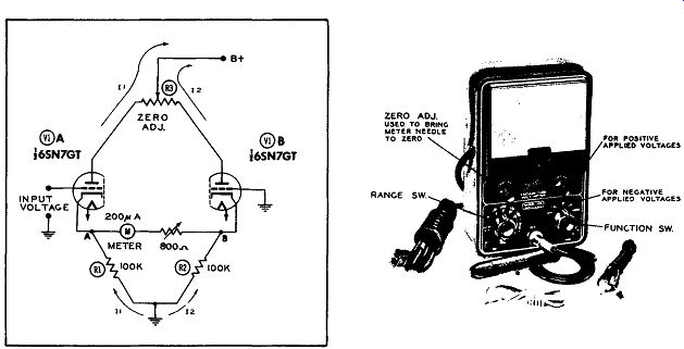
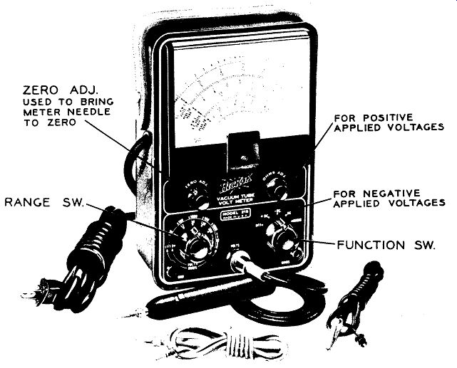
Figure 1. The Basic Circuit of a Modern VTVM. Figure 2. The Front Panel Controls
on a Typical VTVM. Courtesy of Hickok Electrical Instrument Co.
To employ this circuit for the measurement of voltages, a voltage is applied between the grid of V1A and ground. If this voltage is positive, the current through V1A will increase, and point A will become more positive than it was. Point B, on the other hand, will remain unchanged since the grid of V1B is grounded.
With a very definite difference of potential existing now between point A and point B, current will flow through meter M from B to A. Just how much current will flow will depend upon the value of voltage applied to the grid of V1A. Consequently, the meter dial can be calibrated directly in volts.
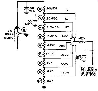
Figure 3. A Voltage Divider Network Across VTVM Input.
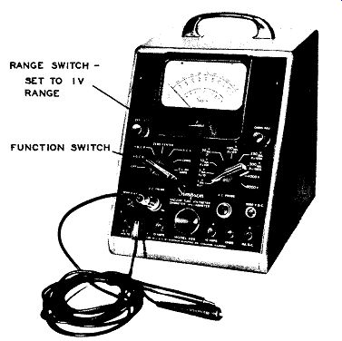
Figure 4. The Simpson Model 266 VTVM Set up to Measure Positive DC Voltages
of 1 Volt or Less. Pay Particular Attention to the Range and Function Switches.
(Courtesy of Simpson Electric Co.)
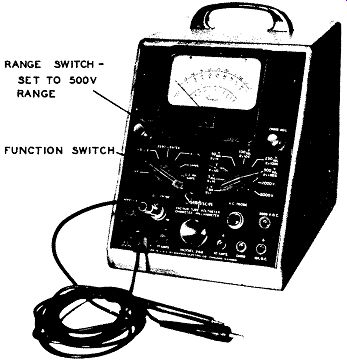
Figure 5. VTVM of Figure 4 Set up to Measure Voltages up to 500 Volts DC.
Nothing Has Changed Except Setting of Range Control. (Courtesy of Simpson Elec.
Co.)

Figure 4. The Simpson Model 266 VTVM Set up to Measure Positive DC Voltages
of 1 Volt or Less. Pay Particular Attention to the Range and Function Switches.
Courtesy of Simpson Electric Co.
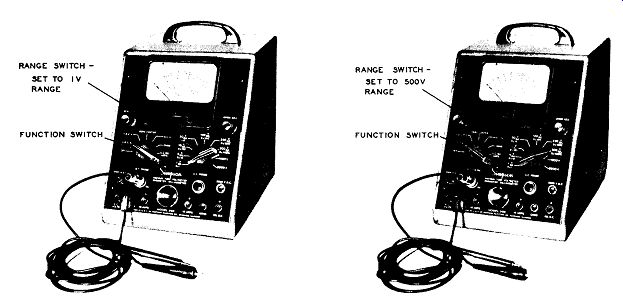
Figure 5. VTVM of Figure 4 Set up to Measure Voltages up to 500 Volts DC.
Nothing has Changed Except Setting of Range Control. Courtesy of Simpson Electric
Co.
When a negative voltage is applied to the grid of V1A, the current through this tube decreases, causing point A to be come less positive and now current will flow through meter M from point A to point B. This will force the meter pointer to move from zero toward the left. Since on most instruments the zero position is already as far to the left as the pointer normally goes, applying a negative voltage to the VTVM would drive the pointer off scale. To overcome this limitation, we may either reverse: the test leads or incorporate a switch which will accomplish essentially the same thing by reversing the meter connections.
This switch is known by a variety of names, but the most widely used is +DC and -DC. See Figure 2.
In order to permit the VTVM to measure a variety or range of voltages, a voltage divider circuit is placed across the input to the meter, as shown in Figure 3. The total value of the resistances in this string is 50 megohms and for the voltage ranges shown (i.e., 1 volt to 1,000 volts), 50 megohms in the input impedance of the VTVM. With an input impedance this high, it can readily be appreciated why the VTVM scarcely disturbs the circuit into which it is connected to measure voltages. This is one of the major advantages of the VTVM. The smallest voltage which will give full scale deflection of meter M is 1 volt (in this arrangement). In practice, this will vary with the instrument, with other common values being 3 and 5 volts. When the meter is to measure voltages of 1 or less, the right hand switch is rotated to the line marked 1 V. Figure 3 shows the schematic diagram for this condition and Fig 4 illustrates the settings of the switches on the front panel of a suitable VTVM. The right-hand range switch is set to the 1 V. position and the left hand function switch is set to +DC. V. The common lead of the meter (coming from the terminal marked "Common") is connected to the negative side of the voltage to be measured and the DC probe is touched to the positive side of this voltage. (In most instances the negative side is the circuit chassis, although in transformerless sets the chassis need not be B-.) If the voltage to be measured had been negative with respect to ground or to the chassis, the measurements could have been accomplished in one of two ways.
1. Connecting the voltage probe to ground or chassis and using the common lead as the probe.
2. Or, the leads could have been employed as they normally are, but the meter reversing switch changed from +DC. V. to -DC. V. This is the preferred method.
To measure voltages greater than 1 volt, the right-hand selector switch of the meter would be turned to the proper scale. Thus, Figure 5 illustrates how the meter would be set up to measure voltages up to 500 volts. Actually nothing has been done except to rotate the range switch so that it now points to the 500 volt marking. Measurements are made using the DC probe and the common lead in exactly the same manner as previously outlined. It's as simple as that.
The selection of the proper voltage scale to make a certain measurement frequently puzzles the beginner. The best scale to use is the lowest one which permits you to obtain a reading without having the needle go off scale. However, when you first start to measure an unknown voltage, use the highest meter scale available. Generally this means 1,000 volts unless you have reason to believe that the voltage is even higher than this. In most television receiver circuits (excepting the high voltage circuit) the DC values seldom exceed 400 - 500 volts.
A zero adjust control is provided on the front panel of vacuum-tube voltmeters to enable the operator to balance the meter bridge circuit and to compensate for any changes that may have occurred to upset this balance. After the meter has been placed in operation (by turning on the power) and the circuit selector switch turned to the desired voltage measuring position, the "Zero Adj." knob should be rotated to the right or left until the pointer is directly over the zero indication on the meter scale. When making this adjustment, the DC probe and the common lead are shorted together. This is to prevent the probe from picking up stray voltages and causing the meter to give a false indication. This is especially important when the lowest DC scale is to be used.
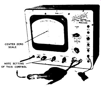
Figure 6. A VTVM With a Special Zero Center Scale. Courtesy of Hickok Electrical
Instrument Co.
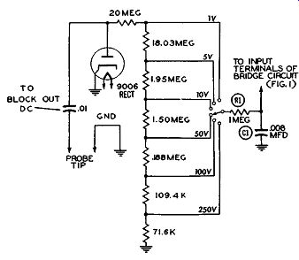
Figure 7. A Simplified Schematic of the AC Voltmeter Circuit of a VTVM.
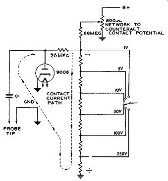
Figure 8. To Counteract the Negative Potential developed by the Contact Potential,
a Small Positive Voltage is Fed Into the Circuit.
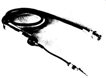
Figure 9. An AC Probe Which Contains the Rectifier Diode. Courtesy of Hickok
Electrical Instrument Co.
The zero adjustment should be checked when ever the range is changed. A number of vacuum-tube voltmeters contain provision for placing the needle at the center of the scale. Internally this is accomplished by unbalancing the bridge circuit until the current flowing through the meter moves the needle to the mid-point of the scale. See Figure 6. If the VTVM is now employed to measure voltages, it will be found that applied positive voltages will cause the meter needle to swing to the right of center and negative voltages will swing it to the left of center.
Zero center reading vacuum-tube voltmeters usually have a separate small scale on the dial face marked with zero in the center. Whether or not this particular scale contains any markings is usually unimportant since the meter in the " Zero Center" position is not employed to indicate specific voltages, but merely to reveal whether the circuit under test is balanced. This is illustrated by a discriminator where a balanced condition will result in a zero center indication while an unbalanced condition will cause either a positive or negative deflection. This particular application will be considered in detail in a subsequent section.
AC VOLTMETER
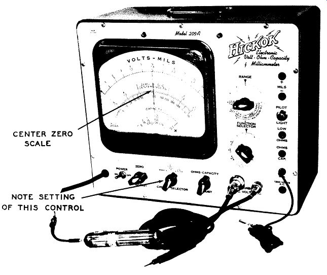
Figure 6. A VTVM with a Special Zero Center Scale. (Model 209A, Courtesy of
Hickok Electrical Instrument Co.)
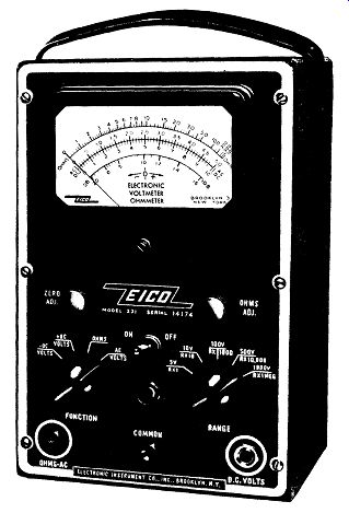
Figure 10B. An Eico VTVM Instrument Is Set up to Measure AC Volts. Note Function
Switch Is Set to AC Volts Position; Setting of Range Switch is Dependent on
Voltage to Be Measured. (Model 221, Courtesy of Eico.)
The measurement of AC voltages with a VTVM is based on the rectification of the AC voltage by a rectifier (usually a diode but sometimes a copper oxide rectifier), and the subsequent application of this voltage to the grid of the input triode of the bridge, causing the bridge circuit to function. In the AC position, the meter will indicate the rms value of the voltage.
A simplified schematic of the AC voltmeter circuit of a VTVM is shown in Figure 7. The AC voltage is applied to a diode where it is rectified and converted into pulsating DC. This voltage is then applied to the control grid of one of the bridge triodes through the appropriate resistors in the input voltage divider string. The voltage is indicated on the VTVM meter in the same manner as an applied DC voltage.
Additional filtering is provided by R1 and C1.
When a diode tube is used for the rectification of the AC voltage, an additional internal adjustment is required. A diode tube will be found to conduct current even with no voltages applied to the plate or cathode, but with the filament heated. This minute current flows from cathode to plate of the diode, through the external resistors to ground and thence back to the cathode again. See Figure 8. The voltage developed across the resistors will be negative with respect to ground and is known as the contact potential. To counteract this negative voltage, an equivalent positive voltage is taken from the power supply and fed into the circuit. The adjustment of this positive voltage is made in the factory and should not be required in the field.
The rectifier diode may be contained in a special probe (such as the unit shown in Figure 9) or it may be situated within the instrument case and a conventional test prod or probe* used for the AC measurements. In some meters there is a separate plug-in jack to which AC voltages are applied and a separate plug-in jack to which DC voltages are applied. In other models, both voltages are brought in through the same terminal. See Figure 10A. Note, however, that in all vacuum - tube voltmeters the range switch has a separate position for the AC and a separate position for the DC. The measurement of AC voltages follows exactly the same procedure as that of DC voltages. The only precautions to observe is that the proper probe is being used and that the selector switch has been shifted from DC volts to AC volts. See Figure 10B. The zero adjustment should be checked on all AC ranges just as it was on all DC ranges.
It may be noted in passing that whenever a VTVM is capable of measuring AC voltages beyond 1,000 volts (approximately), that it contains separate pin jacks to which this higher voltage must be applied.
Thus, in Figure 4, there is a separate terminal for all AC voltages beyond 1,000 volts (1,000 - 5,000 volts). The unit in Figure 6 has a separate jack for AC volts from 300 to 1,200 volts. (The pin jack is labeled 1,200 volts AC but this represents the highest AC voltage which can be measured.)
* The names "test prod" and "test probe," or just plain "prod" and "probe," are used interchangeably by most instrument manufacturers and by servicemen. This same practice will be followed here.
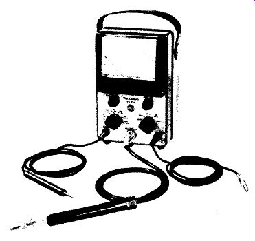
Figure 10A. A VTVM in Which AC and DC Voltages are Fed to the Same Terminal.
Courtesy of RCA.
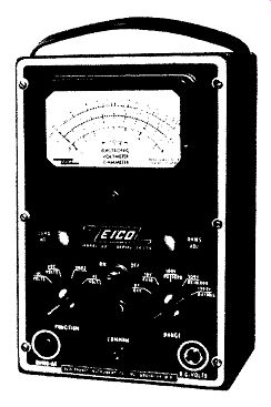
Figure 10B. An Eico VTVM Instrument is Set up to Measure AC Voltages. Note:
Function Switch is Set to AC Volts Position; Setting of Range Switch is de
pendent on Voltage to be Measured. Courtesy of Eico.
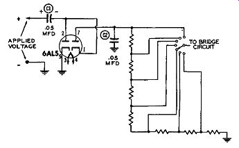
Figure 11A. A Voltage Doubler Circuit for Peak-to peak Measurements. The Positive
Peak Voltage Appears Across C1. See Text.
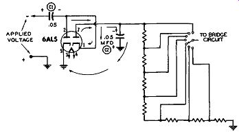
Figure 11B. The Full peak-to-peak Voltage Is Developed Across C2. See Text.
PEAK-TO-PEAK READINGS. In servicing the deflection systems in a television receiver, it is frequently necessary to measure the peak-to-peak value of the voltages developed. To accomplish this, some vacuum - tube voltmeters contain a voltage doubling circuit of the form shown in Figure 11A. The peak-to-peak value of the applied voltage is developed across C2 in the following manner: Assume that the positive ha1f - cycle of the applied wave is present at the input terminals to the meter. Under these circumstances, current will flow from the cathode (Pin 5) to the plate (Pin 2) and thence to the right-hand plate of C1. An equivalent number of electrons will then flow from the left-hand plate of C1 through whatever circuit is attached to the input terminals of the meter and down to ground.
From ground the electrons will flow back to the cathode (Pin 5) of the tube again. In this current flow, C1 will have developed across it a voltage equal to the peak value of the positive half of the applied voltage, regardless of its wave shape.
During the following negative half-cycle of the applied wave, the polarity across the input meter terminals is reversed. See Figure 11B. If we now compare the polarity of the voltage across C1 with the negative polarity of the applied voltage, we see that they are in series with each other. Further tracing shows that the most negative end of the two series voltages is applied to the cathode of the second diode (Pin 1 in Figure 11B), while the most positive end of the series voltages is at ground potential.
Since the plate of the second diode (Pin 7) is essentially connected to ground through capacitor C2, we have a situation here where current will flow through this second diode, charging C2 to the peak potential of both applied voltages. Then, whatever voltage is developed across C2 will be applied to the voltage divider chain and from the appropriate point on this string fed to the control grid of one VTVM bridge tube.
It is important to note again that the arrangement shown in Figure 11B will provide an indication of the peak-to-peak value of the input wave, irrespective of its shape. This is most important because the rms or average value of a wave will change with its waveform and any peak-to-peak value obtained by relying on rms or average values will be incorrect unless the meter is calibrated for that particular waveshape and the waveshape is kept constant for all measurements (which it very seldom is). When a VTVM is equipped to measure peak-to-peak values of any wave, it will usually have a separate selector switch position (or perhaps a separate probe other than the normal AC probe) for it. See Figure 6. Be sure to set the switch to this position.
Also check to see whether the meter contains a separate peak-to-peak scale. Some units do, some do not. W her e there is no separate scale, simply use the existing AC scale. The value indicated by the needle for any applied voltage will be the full peak to-peak value of that wave.
As an illustration of the procedure to follow when using the instrument of Figure 6 to measure normal AC voltages and peak-to-peak voltages, here are the instructions as given by the manufacturer.
A. For measuring normal AC voltages (i. e., to obtain rms values):
1. Turn the "Power" switch ON.
2. Connect the AC probe to the outlet provided for it.
3. Connect the black unshielded test lead to the "GND" jack.
4. Turn the "Function Selector" switch to VOLTS AC.
5. Turn "Circuit Selector" switch to NORMAL.
6. Turn the "Range" switch to the range which will cover the voltages to be measured. If this is unknown, choose the highest range.
7. Check the meter for zero setting. Adjust to zero with the "Zero Adjust" control.
8. Connect the AC probe and the black test lead to the voltage to be measured.
9. Read the numerical value from the scale directly and apply the multiplying factor for the position of the "Rangel' switch.
B. For measuring peak-to-peak voltages:
1. Procedure for AC peak-to-peak measurements is identical to that outlined above with the exception of Step 5 which, in this case, should be changed to "Peak-to-Peak." On some vacuum-tube voltmeters there is no special probe or selector switch position for peak-to peak voltages, but still a separate peak-to-peak scale will be found on the face of the meter. See Figure 2.
The markings on this scale are designed to indicate the peak-to-peak value of sine waves only. (In a sine wave, the peak-to-peak value is 2.83 times the rms value.) This type of meter will not correctly give you the peak-to-peak value of any other shaped wave because each marking on this peak-to-peak scale is 2.83 times the corresponding value on the AC scale just above it and this factor of 2.83 does not apply to waves other than a sine wave.
As an illustration, consider the deflection wave shown in Figure 12A, and assume its peak-to-peak voltage is 50 volts. Within its circuit, this wave extends for 20 volts in the positive direction and 30 volts in the negative direction. If we employed an rms reading VTVM, it would indicate a value of about 14 volts. This is because the AC voltmeter section of a VTVM uses a diode which responds only to the positive portion of the applied wave, becoming non conductive throughout the negative portion. (See Figure 7.) Conventional vacuum tube voltmeters are calibrated to read an rms value which is . 707 times the peak-positive value of the applied voltage. (Pro viding the applied voltage is a sine wave.) If now we multiplied 14 by 2.83, we would obtain the erroneous peak-to-peak value of 39.6 volts.
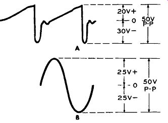
Figures 12A and B. The VTVM Must Contain a Special Circuit to Indicate Correctly
the Peak-to-peak Value of Waves Other Than Sine Waves. See Text.
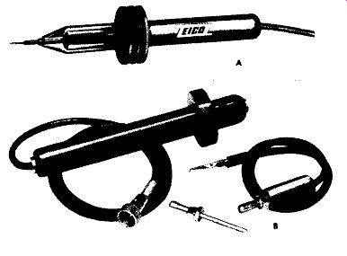
Figures 13A and B. Two High-voltage Probes Designed for Use With Vacuum-Tube-Volt-Meters.
(A) Courtesy of Eico and (B) Courtesy of Hickok.
If we had a sine wave with the same 50 volts peak-to-peak value (Figure 12B), 25 volts would ex tend in the positive direction and 25 volts in the negative direction. The VTVM, responding to the peak of the positive half cycle, would record an rms value of 25 x .707 or 17.7 volts. On an adjacent peak-to-peak scale, this 17.7 multip1ied by 2.83, would yield the correct 50 volts (approximately) peak-to-peak value. But note again that this occurs only because the meter is designed around the 707 factor which is derived from sine wave relationships.
HIGH-VOLTAGE MEASUREMENT
The top DC voltage range of 1,000 volts found on most vacuum-tube voltmeters is more than sufficient for the measurement of any of the low DC voltages ordinarily encountered in television receivers. However, the cathode - ray picture tube operates at an accelerating potential of from 9,000 to 25,000 volts and some method should be available to the technician for measuring these high potentials.
Fortunately the input impedance of the conventional VTVM is so high that by means of special probes, any VTVM can have its DC voltage range extended to 25,000 or 50,000 volts. (Some high-voltage probes extend the VTVM range only to 10,000or 15,000 volts, but the majority of probes go higher than this.)* The low current drain, arising from the high input impedance, is important because the high-voltage power supplies in television receivers normally deliver less than half a milliampere (500 microamperes) and any meter which would draw more current than this would lo ad the circuit down sufficiently to kill the high voltage.
The physical appearance of two high-voltage probes are shown in Figures 13A and B. Each probe is long and on each there is a safety flange to protect the serviceman from coming in contact with the high voltage to be measured and also to protect him from arcing or corona. Either of these can be just as harmful as di r e ct contact. Within the probe is a very large series resistor across which the bulk of the applied high voltage is dropped. For example, if a probe is designed to measure 25,000 volts, then 24,000 volts might appear across the probe internal resistors and only 1,000 volts actually applied to the VTVM itself.
--------------
* High-voltage probes are also available for 20,000 ohm per vol1t multimeters. A 1,000-ohm per voltmeter cannot be used for high-voltage measurement because the current it would draw would reduce the high voltage considerably below its normal operating value.
-------------------
To employ the high-voltage probe, its connector cable is inserted in the DC vo lt terminal of the VTVM. The common lead of the meter is securely fastened to the television receiver chassis. In transformer less television receivers, an isolation transformer should be inserted between the receiver and the AC line. If this is not done, and you connect the meter common (or meter ground) to the receiver, you may very well be placing a short across the AC power line, with accompanying disastrous results.
(If an isolation transformer is not available, make the measurement as outlined, but keep the meter case and chassis from making direct contact with any ground, such as an electric conduit pipe on the bench.) The next step is to set the VTVM selector switch to the proper setting. In most instances this is the highest DC voltage range, say 1,000 volts.
Just how much each value of this range must be multiplied (say 10, 15, or 30 times) depends upon the resistance of the high voltage multiplier. Which brings up a very important point. The high voltage multiplier that is used with a specific VTVM should be designed expressly for that VTVM. Just how much multiplication is required for a certain scale when the high-voltage probe is attached will depend upon (a) the internal resistance of the VTVM and (b) the resistance of the dropping resistor in the body of the high-voltage probe. Any change in the resistance at either point (probe or VTVM) will alter the voltage distribution and, with it, the amount indicated by the meter.
It is quite evident, therefore, that unless you use a high-voltage probe designed specifically for your VTVM, the meter readings will be incorrect unless you know the proper multiplying factor.
Along these lines, it is not safe to assume that two different model vacuum-tube voltmeters marketed by the same manufacturer utilize the same high-voltage probe. As an illustration, consider the Simpson Model 266 VTVM and Model 303 VTVM. The probe for the Model 266 has an internal resistance of 1205 megohms. To use this probe, the Model 266 meter selector switch is set to the 1,000-volt scale, but when readings are taken, you note where the meter needle is along the 250-volt scale and then multiply this by 100.
However, to measure high-voltage with the Model 303 VTVM, you use another probe having an internal resistance of 9 91 megohms. Also, on this meter, you set the selector switch to the 1,000-volt scale and then multiply whatever reading you obtain on this scale by 100.
If you should happen to know what the probe resistance should be for your VTVM, then, of course, you may use any probe having this value of internal resistance. But in the absence of such information, do not interchange probes.
Finally, it is a good rule to keep one hand in your pocket when making high-voltage measurements.
And the other hand, which holds the high-voltage probe, should be kept as far away from the contact end as possible. See Figure 13C.
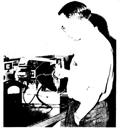
Figure 13C. How to Use High-Voltage Probe Properly.
In a television receiver, the only place where the high-voltage probe is normally employed is at the accelerating anode of the picture tube. If the voltage is measured with the high voltage lead disconnected from the tube, then the setting of the brightness control is unimportant. However, if the measurement is made with the high-voltage applied to the tube, it is advisable that the brightness control be turned down so that the screen is not illuminated.
This is done because the power possessed by the high-voltage supply is quite small and any increased drain will cause the voltage to drop rather sharply. Normally, the picture tube draws several hundred microamperes; however, when the probe is also brought in contact with the high voltage, its added drain may be enough to cause this potential to drop, leading to an erroneous reading. By turning down the brightness control, we remove the tube drain and thereby permit the meter to record a truer value of the existing high voltage.
R.F. PROBES
The outstanding advantage of the VT VM as a measuring device is its ability to perform this function without appreciably disturbing the circuit in which the measurements are made. For DC circuits and in low-frequency networks (up to approximately 15 khz) we can employ a pair of ordinary leads with the VTVM to make whatever measurements are needed, without unduly disturbing the operation of the circuit under test.
As the operating frequency of the circuit rises, the disturbing influence of the leads increases. Alternating voltages, we have seen, are measured by bringing them to a rectifier in the VTVM where they are converted into pulsating DC and from this, the rms value of the voltage is obtained. Now, as the operating frequency of the circuit rises, we know that the capacitance and inductance in that circuit de creases. Another way of looking at this is to say that with frequency increase, a circuit becomes more sensitive to capacitance and inductance changes.
Moving a wire only one-quarter of an inch in a 200 mhz circuit will cause a greater frequency disturbance than moving a wire several inches in a low-frequency circuit.
Because of this sensitivity , measurements in high-frequency circuits must be made with an instrument which introduces far less extraneous capacitance and inductance than a pair of test leads.
Toward that end, special RF or high-frequency probe attachments for VTVM instruments have been designed wherein the rectifying element is brought as close to the voltage to be measured as is feasible.
This reduces shunting capacitance to a minimum and, at the same time, keeps the amount of lead inductance extremely low.
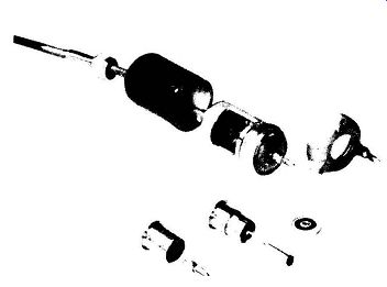
Figure 14A. Exploded View of Diode High-frequency Probe. Courtesy of General
Radio.
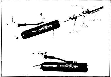
Figure 14B. A Crystal-diode Probe and its Internal Construction. Courtesy
of RCA.
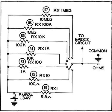
Figure 15. The Ohmmeter Section of a VTVM.
Two types of rectifiers have been used in these probes: miniature diodes and crystal rectifiers. The diode is advantageous because it is capable of measuring higher voltages than a crystal. Its disadvantage lies in the fact that it requires filament voltages and these must be brought to the tube through the leads connecting the probe to the VTVM proper. The construction of the crystal probe is simpler (no heating power is required), but to date the voltages which it can safely measure seldom exceed 20 volts. It is partially possible to by-pass the voltage limitation of the crystal with capacitive voltage di'\tiding networks, but these introduce additional shunting capacitance that is not desirable.
Exploded views of a diode probe and a crystal probe are shown in Figure 14, A and B. The diode probe (here) uses a 9005 acorn tube, chosen especially for its low input capacitance (1.0 mmf.) and small lead inductances. The crystal probe uses one of the many germanium crystal units commercially available.
Precautions to be observed when using the RF probe are first, to know the maximum voltage which can safely be applied to the probe without injury and second, the frequency range throughout which its indications can be relied upon. These specifications are either indicated in the instruction sheets provided with the probe or they can be obtained from the manufacturer. While the voltage limitation of diode probe units is seldom serious, their frequency limitations can be -- especially in view of the forthcoming use of the UHF band for television reception.
When using the high-frequency probe to make measurements, place the probe end directly on the point whose RF potential is to be measured. The grounding lead of the probe should be kept short and grounded close to the measuring point.
Circuit components should be disturbed as little as possible when making RF measurements; also, keep your hand and other parts of your body as far away from the circuit as possible. Above all, do not indiscriminately push leads and components aside in order to get at the point where the voltage is to be measured. Pick your way through the circuit care fully.
OHMMETER
The ohmmeter section of a VTVM is shown in Figure 15. A small battery (such as the Mallory RMBZ4, 1.34V unit) is used to supply the potential.
This potential, when applied to the grid of one triode section of the 6SN7 tube is sufficient to cause full scale deflection of the meter. A variable control, marked "Ohms Adj." on the front panel, permits the operator to accurately position the meter needle so that it stops directly over the final right-hand marking of the "Ohms" scale. This is done with no resistor connected between the "Ohms" and "Common" terminals of the meter and with the leads from these terminals NOT touching. The needle position at the other end of the scale should also be checked by the procedure previously outlined, i. e., with the meter leads shorted together. The "Zero Adj." knob is used this time to bring the needle directly over the zero line.
When the resistance under test is connected between the "Common" and "Ohms" test leads, a voltage divider circuit is produced consisting of the 1.34V battery in series with one of the standard resistors R1 to R7 and the resistor under test. The voltage across the unknown resistor is proportional to its resistance. This voltage is applied to the grid of one section of the bridge circuit which produces a meter deflection proportional to the unknown resistance.
Modern vacuum-tube voltmeters are capable of measuring resistances up to 1,000 megohms (some units even go beyond this). This is 1,000,000,000 or one billion ohms and is more than sufficient for any normal service work.
When the ohmmeter is not in use, the meter needle remains at the extreme right-hand side of the scale at the "Inf." mark. This is opposite to its resting position when in use on other scales, such as volts or milliamperes. (An exception to this is the VTVM shown in Figure 16, where the zero position for volts is at the center.*) The most important fact to remember when measuring resistance is, first, to remove all voltages from the circuit in which the resistor whose value is to be checked is located. Secondly, zero the meter at the low end (using the "Zero Adj.'' control) and position it accurately at the upper end of the scale (using the "Ohms Adj." control). At the low end, the meter leads a r e shorted together; at the high end, they are kept apart. Also, use the scale that brings the needle i n to the less congested portion of the scale. On vacuum -tube voltmeters, this is the center and left-hand section of the scale.
-----------
* The zero center vo lt scale in this instrument eliminates the need for a polarity reversal switch and minimizes possibility of meter overloading when measuring voltages of unknown polarity.
-----------------
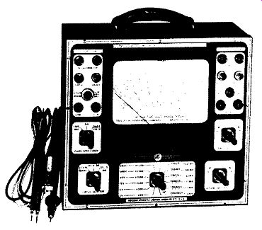
Figure 16. A VTVM With Zero-center Volt Scale.
Courtesy of Precision Apparatus Co.
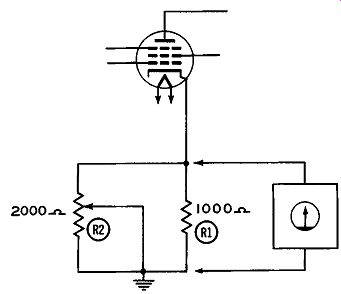
Figure 17. The Measured Value of R1 (Without Re-moving From Circuit) Is Dependent
Upon a Center Arm Setting of R2.
The greatest difficulty that the serviceman may encounter when using the ohmmeter is to measure the value of a resistor while this resistor is still in its circuit. Simply placing the ohmmeter leads across the resistor will not necessarily give you the true value of this resistor. It all depends upon whether or not there are other resistors in the circuit shunting the one under test. To illustrate, suppose the value of R1 in Figure 17 is to be determined.
Actually, if you glance at this circuit, the value indicated by the ohmmeter can be anywhere between 667 ohms and zero and any of these values would be entirely correct. R1, you see, is shunted by a variable 2,000 ohm resistor, R2. When R2 is set so that its entire resistance is in the circuit, the 1,000 ohms of R1 is shunted by the full 2,000 ohms of R2 and the resultant value is: R (resultant) = R1 x R2 R1 + R2 1000 X 2000 3000 = 667 ohms (approximately)
On the other hand, when R2 is taken completely out of the circuit, by moving the grounded center arm to the top of the resistor, R1 is likewise grounded out and the total resistance value is zero.
Since there is no way to determine the true value of R1 while it is in the circuit, the only thing to do is to unsolder one end of this resistor and then measure its value.

Figure 16. A VTVM with Zero-Center Volt Scale. (Model EV-10, Courtesy of Precision
Apparatus Co.)
Only when it is definitely known that a resistor is not shunted by other resistances may its true value be determined without removal from the circuit.
Another difficulty which is frequently encountered by the serviceman is the measurement of resistances in circuits where large valued capacitors are shunted across the resist or under test. To understand what will happen in these circuits when the ohmmeter leads are placed across a resistor, two facts must be known. First, as we have noted above, the ohmmeter circuit in the VTVM contains a small battery and it is the voltage drop developed across the resistor under test that determines how much resistance the VTVM will indicate. Secondly, when a voltage is applied to a circuit containing resistance and capacitance, the voltage across the capacitor does not immediately rise to its full value. Some definite time must elapse before this can occur and the length of time depends upon the amount of resistance and capacitance present in the circuit. When the resistance value is low and a relatively small capacitor is used, then the time required by the capacitor to charge may be so short as to appear instantaneous. In this case the serviceman will not be aware of any time lag between the time he places tire probe in the circuit and the time he glances at the meter for a reading. However , if the resistance and/or capacitance values are high, then he will see the meter needle move up gradually, taking several seconds, or longer, before it comes to a complete stop.
Consider, for example, the circuit shown in Figure 18A. When the ohmmeter leads are connected across this circuit, the meter pointer will initially jump up to 1 megohm and then slowly and gradually work its way up to 4 megohms. If we assume that the 20 mfd. capacitor is uncharged at the s tart , then when the ohmmeter is connected across the circuit, the capacitor acts as a short circuit across points A and B. The meter thus initially sees only 1 megohm and that is all the resistance it indicates on its scale. Gradually, however, as the capacitor charges up, more and more of the current flows through the 3 meg-ohm resistor. When the capacitor has become fully charged, no current (or at least very little) will be diverted away from the 3 megohm resistor and now the ohmmeter will indicate the full 4 megohms of resistance present in the circuit.
If the 20 mfd. capacitor shunted both resistors, as in Figure 18B, then initially the meter needle would go down to zero and then slowly rise back up until it reached a value of 4 megohms. At this point it would stop.
This concept of an· uncharged capacitor acting as a short circuit when a voltage is applied across it follows quite logically from capacitor action. Electrons flow from the negative side of the battery into the nearest capacitor plate and an equivalent number of electrons leave the other plate and flow toward the positive side of the battery (or power supply). Since the capacitor offers no electrical opposition at the start, the amount of current flowing through the circuit will be limited solely by any resistance that may be in series with the capacitor. With continued current flow, however, a charge develops across the capacitor which acts in opposition to the applied voltage, gradually reducing the amount of current flowing through the capacitor. When the capacitor becomes fully charged, all current flow through it ceases.
Keep in mind that the charging time is governed by the values of the resistances and capacitors in the circuit. This includes whatever resistance is present in the meter, too. Thus, consider the ohm meter circuit in the VTVM of Figure 15. When the meter selector switch is s et for Rx1 megohm, the 1.34 volt battery has a 10 megohm resistor in series with it. This 10 megohm resistor plus the 20 mfd. capacitor in the external circuit causes the voltage across the capacitor to rise slowly and in consequence the meter needle will also move up the scale slowly.
And until the capacitor reaches a value which, in Figure 18C, is 4/14 of 1.34 volts, the VTVM meter needle will continue to move slowly up the scale.
Were it not for the presence of the 20 mfd. capacitor, the current flow (and hence, voltage distribution) in the circuit would be instantaneous and the full meter indication would be obtained as soon as the meter leads were connected across the circuit.
It is only when large capacitors are introduced into the circuit that the slow rise of the meter needle occurs.
Sometimes other complicating factors enter the picture just outlined. Thus, if the leakage resistance of the 20 mfd. capacitor (which is of the electrolytic type) is quite high, as it is in a good unit, then the action described will take place, as the serviceman may determine for himself. However, if the electrolytic capacitor has been in use for some time, its leakage resistance may be low enough to produce a final meter reading of less than 4 megohms.
This is another pitfall that the technician will have to guard against when he measures resistances with out removing them from the circuit. All in all, a lot less trouble is encountered if one end of the resistor is disconnected from the receiver circuit before its value is measured.

Figures 18 A, Band C. Circuits to Illustrate Why Meter Needle Will Rise Slowly
on Some Resistance Measurements.
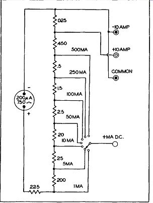
Figure 19. A Simplified Milliammeter and Ammeter Circuit Used in a VTVM.
CURRENT MEASUREMENTS
In comparison to the number of times the voltmeter and the ohmmeter sections of the VTVM are used, there are relatively few occasions when current is measured. For this reason some of the vacuum-tube voltmeters on the market do not contain any provision f o r current measurement. However, for those units which do, the circuit shown in Figure 19 is typical of the arrangement employed. On examination this is seen to consist simply of a sensitive meter (200 m i c roam p movement) with a suitable array of shunting resistors. The shunt resistors are arranged so that for full scale deflection in each range, a current of 200 microamperes flows through the meter. The balance of the current is directed through the associated shunt resistors. When large currents are to be handled, say on the order of 10 amperes or more, special terminals are employed on the front panel. There is one positive terminal and one negative terminal. Heavy_ wires capable of handling large currents connect these terminals to the meter. Since the vacuum-tube circuits do not enter into current measurement, there is no need to plug the VTVM into the power line. Merely set the function Selector Switch to the "MA" position and connect the meter leads into the circuit where the current is to be measured. The "Range" switch is used for low currents but large currents (10 amps or more) are never shunted through the switch.
A good precaution to observe when measuring large currents is never to remove the pin jacks from the meter terminals while the current is flowing through the circuit. Breaking the circuit while this much current is present will produce a sizeable arc at the pin. This may not injure the meter, but it will cause the terminal jack to char in time.
DECIBEL (DB) MEASUREMENTS
A number of vacuum-tube voltmeters contain a decibel range with which comparative measurements may be made in the audio section of a receiver. The decibel scale in most vacuum-tube voltmeters is so calibrated that it will read 0 db when .006 watts (or 6 milliwatts) is being dissipated in a 500-ohm line. If you are using this meter to determine the db level at a certain point in the audio amplifier system of a receiver, the impedance should be 500 ohms if you wish to obtain a correct comparative reading. If the load impedance is any other value, conversion to the new impedance will be necessary. Suitable conversion tables are furnished either by the manufacturer of the instrument or are available in textbooks or technical magazines.
The principal application of db meters is that of a power level indicator of AC voltages across known impedances in audio circuits, and consequently the select or switch of the VTVM is set to the AC Volts position. (Some manufacturers include a db notation with the AC Volts on the selector switch, and some do not.) The setting of the range switch depends on the design of the instrument and recourse to the instruction booklet is necessary. Also, for different decibel scales in the same instrument, different settings of the range switch are necessary.
Note that since the 0 point on the meter db scale is based on a certain standard, less power than this will cause the needle to stop to the left of the 0 mark. This position on the db scale is marked off in negative units, such as -5, -10, -15, etc. Where the power is greater than the standard, the db indication will be positive.
If you are going to make any use of the db scale in your VTVM, note again that its markings are of value only if the load impedance across which the measurements are being taken is equal to that used in the calibration of this particular scale. It is also well to keep in mind that while most vacuum-tube voltmeters have a db scale based on 0 db= 6 mw, some are based upon a zero level of 1 mw across a 600 ohm line. The readings of the two, while capable of being converted from one to the other, are not the same when taken directly from their respective scales.
OTHER MEASUREMENT SCALES
A small number of vacuum-tube voltmeters, like the one shown in Figure 6, are also capable of measuring capacitances. In the instrument of Figure 6 (and in all other vacuum -tube voltmeters possessing similar provision) the theory of the capacity measurement resembles that of the ohmmeter, with the impedance of the unknown capacitor replacing the unknown resistance. However, since an AC voltage is needed to measure capacitance, and since only DC can be applied to the input grid of the bridge tube, some means must be used to rectify the AC. This is accomplished by using (in this instance) one diode section of a duo-diode tube. The output of this rectifier is then fed to the input grid of the bridge tube.
It is difficult to make any but the most general statements with regard to the exact procedure to follow when making capacity measurements since each instrument has its own method of approach. The only advice that can be given is to refer to the instruction booklet for the instrument.
DEFECTIVE CAPACITOR TESTS. In the servicing of radio and television receivers, it is generally more important to determine whether a capacitor is good rather than what its value is. If a capacitor checker is available, it may do the job. But in the absence of such an instrument, certain tests can be performed with a VTVM which will give you a fair idea whether or not the unit is faulty.
If a coupling capacitor is suspected of being leaky, a DC voltage measurement from grid to ground of the following tube should reveal the trouble. See Figure 20. Normally, all stages which are capacitively coupled in a radio or TV receiver operate with negative bias. If the coupling capacitor is leaky, current will be able to flow through it, developing a voltage drop across Rg. To insure that any positive voltage noted across Rg is not a result of a gassy tube, the tube can be removed or another one, known to be good, substituted in its place.
Another method which has been employed successfully to determine the condition of a capacitor is to disconnect one side of the capacitor from the circuit and then measure its resistance. A good paper or mica capacitor will show a slight deflection on the R x 1 meg range and the reading will quickly approach full scale. The smaller the capacitance value of the capacitor, the smaller the needle deflection, leading ultimately to an inconclusive test when the capacitance becomes too small.
An electrolytic capacitor may be checked the same way, with observance of polarity. That is, the lead connected to the negative terminal of the battery which is located inside the VTVM should go to the negative lug on the capacitor and the other, positive, lead to the capacitor positive lug. Since an electrolytic capacitor will charge more slowly (because of its value), it is recommended that these be checked on the R x 10K range.
An open capacitor of any type will not give any meter deflection from the full scale point. A faulty capacitor will have a resistance value far below the megohm range.
The foregoing ohmmeter tests are useful but it must be recognized that with them we are testing the capacitor at a very low voltage. Frequently a capacitor becomes faulty only when its normal, higher voltage is applied. Hence, if the tests were carried out at the higher voltage, a truer picture concerning the condition of the unit would be obtained. A method of performing these tests at the rated voltage of the capacitor is as follows:* In the method to be described, a high DC potential is applied to the capacitor in series with the proper DC Volts range (VTVM) to determine whether or not it has low insulation resistance or abnormal leakage.
The necessary DC potential can be obtained from an external high voltage DC power supply or from the power output tube socket of a radio receiver.
In the latter instance, the plate prong position of the socket will be the positive high voltage lead, and the negative return or ground will be the negative lead.
PROCEDURE:
1. Measure and adjust the DC voltage obtainable from the DC power supply. Then select the proper meter range that would indicate full scale deflection for the voltage there available and in keeping with the capacitor rating.
----------------
* This method and the one to follow are described in the Precision Model EV-10A VTVM instruction booklet.
--------------
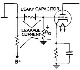
Figure 20. A Leaky Coupling Capacitor Will Place a Positive Potential at the
Grid of the Following Tube.
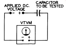
Figure 21. Set up to Check Leakage Resistance of a Paper Capacitor.
2. With the power supply OFF, insert the capacitor to be tested in series with one of the meter test leads. See Figure 21.
3. Turn ON power supply. An instantaneous deflection due to the charge of the capacitor will be indicated on the DC meter.
(A) In ca s e of a good capacitor, the needle pointer will recede to (or VERY close to) the zero voltage mark.
(B) If the meter pointer remains noticeably above the zero mark, this indicates that the capacitor has abnormal leakage.
(C) If the meter pointer remains at the indicated value of the voltage measurement obtained primarily, then the capacitor is "shorted".
(D) If no meter deflection is obtained, it indicates that the capacitor is "Open" or that the capacity is too low in value to indicate an instantaneous noticeable meter deflection when charged.
NOTE: After this test is completed, always FIRST disengage the negative test lead from circuit BEFORE turning off power supply to prevent slamming of needle pointer du e to discharge of capacitor under test.
This method of using a relatively high DC potential in series with a DC VTVM to qualitatively check paper capacitors is superior to a simple high range ohmmeter check because the high potential tends to "search out" capacitor defects which could cause breakdown at operating potentials. The low battery voltage of the ohmmeter circuit (1-3 volts) is insufficient to perform the "searching" function.
The foregoing test is designed for paper or mica capacitors; it is not to be used with electrolytic capacitors. For the latter, the best test to perform is a leakage test and this requires that the VTVM be capable of measuring current.
MEASUREMENT OF LEAKAGE IN ELECTROLYTIC CAPACITORS. The leakage in an electrolytic is measured in terms of direct current (per micro-farad) flowing through the capacitor, when rated DC voltage is applied.
All electrolytic capacitors contain an inherent leakage. However, if leakage above an allowable amount is present, it can then be termed as poor.
Allowable current leakage is dependent upon such factors as age and manufacturers' specifications of a capacitor, design of power unit, filter system and rectifier tube of the receiver in which the capacitor is incorporated. In general , considering an 8 mfd. capacitor THAT HAS BEEN IN USE (rated at 450 volts) the maximum allowable leakage is approximately .5 ma. per microfarad or 4 ma. total.
The following will serve as a basis for computing approximate leakages:
1. For capacitors rated at 300 volts or more, leakage of approximately .5 ma. per microfarad is permissible.
2. For capacitors rated between 100 to 275 volts , permissible leakage is approximately .2 ma. per microfarad.
3. For capacitors rated below 100 volts, permissible le aka g e is approximately .1 ma. per microfarad.
CAUTION: WHEN OBTAINING ELECTROLYTIC LEAKAGE MEASUREMENTS, HIGH VOLTAGE IS EMPLOYED. IT IS THERE FORE EXTREMELY IMPORTANT THAT THE FOLLOWING INSTRUCTIONS BE ADHERED TO IMPLICITLY TO PREVENT DAMAGE TO METER. PROCEDURE: With capacitors disconnected from radio receiver circuit, check capacitors for short with ohmmeter using 0-200,000 ohms range. Polarities must be observed.
In some instruments the negative terminal of the ohmmeter battery is grounded while in others it is the positive terminal. A check of the schematic diagram of the instrument (in the instruction manual) will reveal the answer, or, it may be determined by connecting another voltmeter across the ohmmeter leads. Once this information is obtained, the negative lead goes to the outside can or negative terminal of the capacitor while the positive lead connects to the anode (positive) terminal of the capacitor. A decided low resistance reading indicates that the capacitor is shorted and should be rejected without further testing.
When an electrolytic incorporated in a receiver is to be tested, the necessary rated voltage is automatically applied and the following connections are made for "forming" and measuring the current leak age, after being (ohmmeter) tested for short.
1. Set "Function" switch to the "MA" position and rotate the "Range" switch to the "600 MA" position.
2. Remove the lead in the receiver which goes to the positive terminal of the capacitor and, instead, connect this wire to the positive(+) "MA" tip jack on the meter in series with a proper limiting resistor.
(Where voltage applied to capacitor is above 100 volts the limiting resistor should be approximately 1,000 ohms. When the applied voltage is below 100 volts, the value of the limiting resistor should be approximately 300 ohms. This limiting resistor is very important and should not be omitted.)
3. Connect the negative (-) "MA" pin jack (this is usually meter "GND." jack) to the positive terminal of capacitor. (From the above connections it can be seen that the meter tip jacks, limiting resistor, capacitor terminals and the voltage source are in series connection.)
4. After series connections are made, turn on switch of the receiver. The meter pointer will now deflect to near full scale and then gradually recede to the zero mark or near zero, after the expiration of about three minutes. This procedure is known as "forming" the capacitor.
NOTE: A steady meter pointer indication without receding to or near zero (after forming process) indicates a shorted or leaky electrolytic and should be rejected without further testing.
5. After "forming", short out the limiting resistor and read current leakage of capacitor under test directly on the 120 ma. scale. If meter reading is under 30 ma., set "Range" switch to a lower position for a better indication. Divide the meter reading by the capacitor value and then check with the rules given previously to determine if capacitor leak age is within acceptable limits.
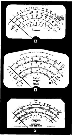
Figure 22. The Meter Scales of Several Vacuum-Tube Volt-Meters. (A) Courtesy
of Simpson Electric Company. (B) Courtesy of Triplett Electrical Instrument
Company. (C) Courtesy of Jackson Electrical Instrument Company.
HOW TO READ METER SCALES
The VTVM, we have seen, is designed to per form a number of functions covering a wide range of voltage, current, and resistance values. Due to the varied nature of these functions, the meter dial face contains a number of different scales, some of which are shown in Figure 22. No two are alike, each differing from the other in some detail. All the vacuum-tube voltmeters, however, are designed to be used in essentially the same manner.
Now, to obtain the proper results from a vacuum-tube voltmeter requires not only that the serviceman knows how to connect the meter into the circuit and how to adjust the panel controls, but that he also knows how to correctly read the meter scale.
And this latter job is far from being as simple as many technicians believe it to be.
The correct reading of a meter scale depends upon knowing three things:
1. The proper scale to read.
2. The value of the markings on that scale.
3. The amount by which each value on the scale must be multiplied.
The first step is to determine which scale to read for the measurements being made. This, in turn, will depend upon the manner in which the instrument is set up. The placement of the function switch tells you what electrical units the meter is in position to measure, whether it be volts, ohms, milliamperes, etc. The other control on the front panel (the range control) will indicate how much of this quantity the meter will measure. Thus, one control will indicate what is to be measured, while the other will tell you how much.
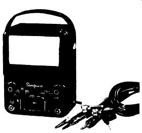
Figure 23. VTVM Simpson Model 303.
To illustrate, in Figure 23, the right-hand knob is pointing to +DC and the left-hand knob to 60. With the controls in these positions the meter will read up to a maximum of 60 volts, DC. Your first job after setting the controls, is noting the prop e r DC volt scale. On the meter in Figure 23, this is the scale labeled "Volts" and is second from the top. The right-hand value of this scale is 12 for the bottom row of figures, 60 for the middle row of figures, and 300 for the top row of figures. Each row of figures (12, 60, or 300) is divided into six sections. Thus, for the 0-12 row, we have 0, 2, 4, 6, 8, 10, and 12. In the second row, 0-60, we have 0, 10, 20, 30, 40, 50, and 60. Similarly, for the top row, there is 0, 50, 100, 150, 200, 250, and 300. The row of figures from which you will obtain your readings will d e p e n d upon the setting of the left-hand (i.e., range) control. In Figure 23, the knob is turned to 60, which means that all readings are to be taken from the 0-60 scale.
We might digress here a moment and note that the left-hand control has five ranges for the "Volts" scale and yet only three ranges are shown on the dial face itself. Missing are the 1.2 volt range and the 1,200 volt range. The answer to this apparent "over sight," of course, lies in the fact that 1.2 volts is 1/ 10 of 12 volts and hence, whenever the control knob is turned to the 1.2 volt position, all readings are taken on the 12 volt scale and divided by 10.
By the same reasoning, when the control knob is turned to the 1,200-volt position, readings are again taken on the 0-12 scale and multiplied by 100. By utilizing one scale for several purposes, a "simplification" in the number of figures required on the meter face is achieved. But if you are unfamiliar with this practice, you r readings can be far out of line. (Incidentally, this practice is extensively employed on other scales of the meter, especially the ohms scale. More will be said of this presently.) Once it has been determined which scale to read, the next problem is the actual reading itself.
In many respects this is the most difficult operation of all to perform and it is here that the greatest number of errors are made. The trouble seems to stem from the difficulty in determining the value of each marking. And yet the process, once learned is no more difficult to perform than any other meter' operation.
To start, consider the relatively simple scale divisions shown in Figure 24. The scale is uniform from one end to the other and contains numbers ranging from 0 to 10.
If you examine the scale closely, you will see that directly below each number is a dark heavy line. All the other lines on the scale are smaller and narrower in appearance. The longer and wider marks can be considered as the major divisions of the scale while the smaller, narrower lines as the minor divisions.
Between every two consecutive numbers say 4 and 5,_ there are four equally spaced markings.. To ascertain the value of each marking, let us first determine the value of the entire space between 4 and 5.
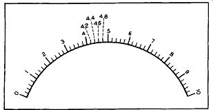
Figure 24. A Simple Scale Containing 10 Major Divisions.
This is done by subtracting the smaller number from the larger one. Here, this means 5 minus 4 or 1.
Thus, 1 must be equally divided into five parts because the four minor lines produce five spaces between 4 and 5. One divided by 5 (or 1/5) gives an answer of .2 and consequently each space (between 4 and 5) is .2. When you get to the end of the first space, just after the 4, the result, if shown on the scale, would be 4.2. At the end of the second space, at the second minor mark, the result would be 4.4. The third small marker is 4.6 and the fourth one is 4.8.
The remaining minor divisions throughout this scale would have a similar value of .2. This means that the value of any individual minor line would be .2 higher than the line to the left of it and .2 lower than the line to the right. This particular relation ship is true over the entire scale because all major divisions are equally spaced from each other and all minor divisions are equally spaced from each other also, (i. e., other minor divisions). This latter point is of considerable importance, although it is not always true, as we shall presently learn.
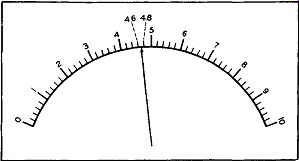
Figure 25. The Pointer Being Between 4.6 and 4.8 Would be Read as Indicating
a Value of 4.7.
If the meter needle should, perchance, stop between two markers, its r ea ding would be some value between those of the two markers. Thus, in Figure 25, the needle is between the second and third small lines, or between 4.6 and 4.8. If the needle is midway between the two lines, its value will be mid way between 4.6 and 4.8 or 4.7. If the needle is closer to the 4.6 mark then it is to the 4.8 mark, you could assign a value of 4.65 to it, but it is problematical whether it would be wise to do so. Actually, in a situation such as this, you might very well assign a value of 4.7 for most needle positions between 4.6 and 4.8. But if the needle came to rest slightly be yond 4.6, its value could be called 4.6; or, if the needle came close to 4.8, the reading could be called 4.8. Meters such as we find in the service shop do not usually possess an accuracy greater than 2 per cent and it is seldom necessary to determine readings any more accurately than what has been noted above.
To recapitulate briefly, note first the major divisions on a scale and then the minor divisions.
Major divisions are characterized by heavier and usually longer lines, and are frequently identified by numbers. Minor divisions seldom have any numbers placed above, below, or beside them.
To determine the value of each marking, count the number of m in or spaces contained between the two adjacent major lines and then divide this number into the difference bet we en the values of the two major indications. The result will be the value of each minor marking. In the above illustration each minor line had a value of .2.
The scale shown in Figure 24 is probably the simplest type of scale you will encounter. A slightly more complex scale is the one shown in Figure 26A. This, too, contains major and minor markings, but some of the major lines are unlabeled, together with all of the minor divisions. Thus, the technician is called upon to determine more than just the values of the minor divisions. However, this complicates the problem only slightly.
On the scale shown in Figure 26A, the figures range from 0 at the extreme left-hand side to 10 at the extreme right-hand side. Actually show on the meter face are the numbers 0, 2, 4, 6, 8, and 10. As a first step, it is necessary to determine the value of all the unmarked major divisions or, in other words, all the longer, heavier lines. Starting at the left hand. side of the scale, the first unmarked major division occurs between 0 and 2. Hence, its value is: 1. The next unmarked major division occurs between 2 and 4 and its value is 3. In similar fashion the values of 5, 7, and 9 for the next three unmarked major divisions c an be ascertained. These are shown in Figure 26B. Once the values of all the major divisions have been obtained, we can turn to the minor markings. In the scale of Figure 26, the minor divisions have the same values as those in Figure 24. In fact, once all of the major division numbers have been determined, it can be seen that this scale and that of Figure 24 are identical.
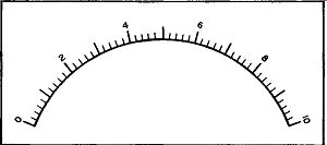
Figure 26A. A Scale Which Is Similar to the One Shown in Figure 24. Note That
Only Alternate Major Lines are Numbered.
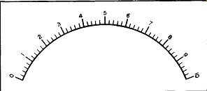
Figure 26B. The Values of the Unnumbered Major Divisions in Figure 26A, as
Shown, Appear in Dotted Form.
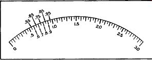
Figure 27. The Value of the Major and Minor Markings on Another Scale. See
Text.
Where the s am e scale is used with several different sets of numbers, as it is in Figure 23 the service-man must be careful to change the value of the various minor divisions as he switches from one range to another. Thus, when the meter is set to operate on the 0-12 volt scale, each minor division has a value of .2. On the 0-60 volt scale, using the same set of markings, each minor division is equal in value to 1. (This follows from the fact that every mark on the 0-60 scale is 5 times its value on the 0-12 scale.) Finally, on the 0-300 range, each minor marking possesses a value of 5.
The scale shown in Figure 27 has a gradation of markings different from those illustrated hereto fore. Here the principal or major divisions are identified by the numbers 0, .5, 1.0, 1.5, 2.0, 2.5, and 3.0. The space between any two consecutive numbers is divided into 5 minor divisions and each minor segment, in turn, is further subdivided in half. For the purposes of this explanation, let us call the smallest divisions, sub-divisions, in contrast to the minor sections.
To tackle first the minor spacings we note there are five between every two consecutive numbers. Also, the difference between each two major sections is .5. Hence, .5 divided by 5 produces a result of .1. This, then, is the value of each minor section. Thus, between .5 and 1.0 we have .6, .7, .8, .9, and finally 1.0. Ascertaining the value of the sub-divisions now becomes quite simple since each sub-division line divides each minor section in half. Hence, .1 divided by 2 gives a result of .05 and this is the value of each sub-division.
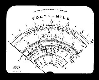
Figure 28. The Scale Used on the Hickok Model 209A VTVM. Courtesy of Hickok
Electrical Instrument Co.
On the Hickok Model 209A VTVM, the Volts Mils scale used is shown in Figure 28. It is employed for volts (AC-DC) and for DC current. Two sets of numbers, 0-3 and 0-12 are found above this scale. The 0-12 is the easier one to figure out, so let's investigate it first. Each number is placed above a major marking; furthermore, between each two consecutive numbers there are five equal sections (produced by four equally spaced lines). Since there are five sections and the difference between two consecutive numbers is 1, each section must have a value of 1/5 or .2. Hence, for the 0-12 scale, each thin line marking possesses a value of .2.
What may prove somewhat confusing here is the fact that not all of the thin lines ( minor mar kings) have the same height. The reason for this stems from the 0-3 scale. So far as the 0-12 scale is concerned, the height variation is not significant. All the minor divisions are equally spaced and all possesses the same value.
Now consider the 0-3 scale. Its major markings are 0, .5, 1.0, 1.5, 2.0, 2.5, and 3.0. Similar dark lines are placed midway between each set of numbers and so each of these other dark lines has an inter mediate value. Thus, the dark line midway between .5 and 1.0 has a value of .75; the dark line between 2 and 2.5 is 2.25, etc.
Now the question is: Why are these intermediate dark lines used? Their values for the 0-3 scale are obviously not significant or at least not as significant as .5, 1.0, 1.5, etc.
The answer is that these intermediate dark lines are actually employed for the 0-12 scale, not the 0-3 scale. However, as long as they are present, their relationship with regard to both scales should be known.
The minor markings for the 0-3 scale fall into two categories. The longer lines could be considered ...
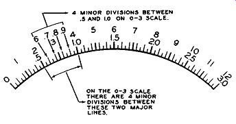
Figure 29. Further Elaboration of a Portion of the
Scale Shown in Figure 28.
... as the true minor divisions while the shorter lines could be classified as sub-divisions. If we consider the longer lines first, then between every two consecutive numbers there are four such lines. See Figure 29. This means that these four lines divide the space up into five sections and hence we must divide the difference in the two major markings (say 1-.5) by five. Doing this, .5/5, reveals that each of these minor divisions has a value of .1. Thus, between .5 and 1 we have .6, .7, .8, .9, and finally 1.0. The values of the smallest thin lines, the so called sub-divisions, can now be readily ascertained.
Each sub-division line is seen to divide each minor space in two. Since each minor space has a value of .1, each sub-division has a value of .1/2 or .05. If we were now to write in the value of each dial marking, it would appear as shown in Figure 30.
NON-LINEAR SCALES
Thus far we have dealt only with meter scales in which the distance between every two consecutive numbers was the same. Technically, this is known as a linear scale. However, there are a number of scales, principally those employed for the measurement of ohms and db, in which the spacings between numbers at different points along the scale varies.
This means that the values of the minor divisions will depend upon the particular section of the scale in which they are located. To illustrate, consider the Ohms scale shown in Figure 31. At the left-hand side of the scale, the numbers are spread out and increase in value slowly. However, as we move to ward the right, the spacing between numbers de creases and the values increase quite rapidly.
The problem is to determine the value of the minor divisions at various points along the scale. At 0 the left-hand side of the scale each two consecutive major divisions have but one minor division between them and consequently the value of this minor division is midway between that of the two major marks on either side of it. Thus, the minor mark between 2 and 3 is 2.5; between 8 and 9 it is 8.5, etc.
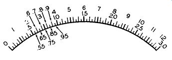
Figure 30. The Value of the Sub-divisions on the 0-3 Scale.
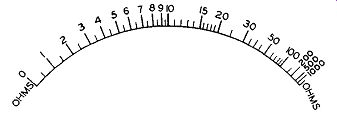
Figure 31. A Typical Ohms Scale.
Over the central portion of the scale, between 10 and 15 (or between 15 and 20), there are five spaces produced by four minor divisions. The difference between 10 and 15 is 5 and this, divided by the five spaces, results in a value of 1 for each of the four minor divisions. Thus, between 10 and 15 we have 10, 11, 12, 13, 14, and finally 15.
Between 20 and 30 there is but one mark and so this must be 25; between 30 and 50 there are several marks although these should cause no difficulty. The center mark, darker and longer than the rest, is obviously 40. The minor divisions on either side of it can then be seen to be 35 (at the left of 40) and 45 (at the right).
The scale at the extreme right-hand end be comes quite crowded and the values rise rapidly.
Again, if any minor divisions appear between the larger markings, count the number of such marks, and divide this into the difference between the two flanking major divisions. This is the method we have employed heretofore.
Generally speaking one scale is employed for all ohms measurements and the serviceman must be careful, when using this scale, to note what positions his multiplier is in. If it is set for R x 100, then every value read on the ohms scale must be multiplied by 100; if the switch is in the Rx 1,000 position, every value is multiplied by 1,000, etc. And, when ever use is made of this scale, the selector switch should be set so that the readings occur to the left hand side of the scale. The markings here are much clearer and easier to read.
To conserve space, especially at the crowded end of the scale where the large numbers are found, 1,000 (and higher values in the thousands) is shortened by the use of the letters K or M. Thus, some manufacturers write 1,000 as 1K, 2,000 as 2K, etc.
Others prefer the letter M; thus, 1,000 is printed 1M, 2,000 as 2M, etc.
In vacuum-tube voltmeters, the ohms scale starts at the left-hand side of the meter dial and ex tends to the right. In multimeters, the direction will vary with the instrument; some scales increase from left to right while others rise in the opposite direction. The methods of using both types of instruments are identical.
The AC scales in some meters will be non linear but in most instruments it will be as linear as the DC scales. The difference is due to the manner in which the AC is rectified in the instrument. Other scales which are generally non-linear are the decibel (or db) and capacitance scales. No difficulty, however, should be encountered in reading these scales if the preceding discussion is fully understood.
To recapitulate, then , correct reading of a meter scale proceeds in three steps.
Step 1. Find the proper scale to read.
Step 2. Determine the value of the markings on that scale. In taking this reading, make sure your eyes are directly over the needle. If you are off to one side, the reading you get will be too high or too low, depending upon which side of the meter you are.
Step 3. Check with the range switch to see if the scale used should be multiplied by some factor.
Multiplication of scale values is most extensively employed for resistance measurements, and to a lesser extent for the other electrical units. However, there is no set practice in this respect and each instrument should be carefully checked for multiplying factors before being used.
USE OF THE VTVM IN TV SERVICING
The principal applications of the VTVM in television receiver service work consists in making voltage and resistance measurements. The low voltage checks are made with an ordinary probe. For high-voltages, a special probe is available, such as shown in Figure 13. An ordinary probe, too, is used for AC measurements (up to approximately 15,000 cycles). Beyond this, extending up for several hundred megacycles, a special RF probe is necessary.
The high-voltage probe and the RF probe are generally additional accessories which are not included in the original pricing of the unit. Where the money is available they should be purchased because they do extend the usefulness of the meter.
While the VTVM is the work horse of the service shop, its usefulness for signal tracing, especially in the RF and IF sections of the receiver, is frequently overlooked.
Yet with a suitable RF probe and perhaps an AM generator to supply a strong signal, a considerable amount of testing can actually be carried out here.
To illustrate how the probe may be employed for signal tracing, consider a television receiver in which, for some reason, the incoming signal is not reaching the video second detector. The problem is to locate the break in the signal path. Tune the receiver to one of the local channels. Then disconnect the antenna and feed in the signal from an AM signal generator. Set the generator to the video carrier frequency for that particular channel. Do not modulate this signal; in other words, feed in an unmodulated signal.
Now, with the RF probe of the VTVM, check for an indication of this signal voltage at the plate of the RF amplifier. (Use the full output of the signal generator and adjust the fine tuning control of the receiver for peak indication on the meter.) Check for the RF signal at the grid of the mixer stage.
Continue the check at the mixer plate and at the grid and plate of each video IF amplifier from the mixer to the video 2nd detector. In each amplifier stage, the signal should be stronger at the plate than at the grid. The only exception to this might occur in the mixer tube, which is not operated as a conventional amplifier, but r at he r as a converter wherein the incoming signal is brought down from its RF value to the IF level. Further investigation should be directed to any amplifier stage where the signal either remains the same or actually decreases in going through the circuit.
The same probe can be employed to measure the RF output of the receiver oscillator. Remove all signals from the front end of the receiver. Then, with the power on, place the RF probe of the VTVM at the point where the oscillator injects its signal into the mixer circuit. (Ground the RF probe shield to the receiver chassis as close to the point of con tact as possible.) Check the output of the oscillator by noting the reading it produces on the VTVM scale.
Do this on every channel on which the receiver is used.
There are several features concerning the use of the RF probe for signal tracing with which the serviceman should be familiar.
1. For best results use an RF generator rather than the incoming signal as the voltage which the probe detects. The generator will provide a useable signal at most frequencies; incoming signals, unless they are exceptionally powerful, will not develop voltage in the first three or four stages of the receiver to give a useable indication on your VTVM.
2. As you go through the front end stages of the set (i.e., those in the tuner) you will find it easy to confuse the voltage fed by the oscillator into the mixer with the incoming signal voltage. The test for the oscillator voltage has already been given. To check for the signal voltage separately at the mixer, it will be necessary to disable the oscillator. Generally, this need not be done if you find a signal in the video IF stages since the presence of this signal indicates an interaction between the incoming signal and oscillator voltage in the mixer. However, when there is no IF signal at the grid or plate of the first video IF tube, then separate tests for the signal and oscillator output at the mixer are warranted.
In dealing with a television receiver, it must be remembered that if you wish to check directly any RF or IF signal (in their respective systems), that an RF probe will have to be used. The RF probe is a detector which takes the signal present at the point-of-measurement, converts it into pulsating DC, and then feeds this voltage to the meter where its rms value is recorded.
If you wait until the signal reaches the video second detector before measuring it, then only the DC probe of the VTVM need be connected to the video load resistor. In this instance the second detector tube takes the place of the RF probe.
As long as you keep the functions of the RF probe in mind, there will be no confusion regarding where it should or should not be used.
ISOLATION TRANSFORMERS
One statement in this section made reference to the use of an isolation transformer when using test instruments to service a transformer less receiver. Other references to this same practice will be found in many of the instructional booklets that come with test equipment. To those men who have not had much servicing experience, these references may appear puzzling since they are almost invariably given without any additional explanation.
The 100-117 volt power line, from which all electrical equipment operates, has one wire grounded and one wire energized. The grounded wire potential remains constant, while the potential of the energized wire, varies alternately above and below ground by 110-117 volts. (While it is common to refer to the power line potential as 110 volts, actually the exact value will vary with each locality. It is not unusual to find variations from 95 to 125 volts not only from place to place, but also within the same locality.) Now, in a transformerless set, such as the AC DC receivers so wide ly employed, the power line connects directly into the receiver low-voltage power supply circuit. See Figure 32. One side of the line becomes the B- for the receiver while the other side connects to the rectifier tube for the development of the B+ voltage.
To the receiver it makes little difference which of the two power line wires is the B- wire and which connects to the rectifier tube. If the grounded power line wire is the B- wire of the receiver, then, of course, the rectifier diode will conduct whenever the energized wire is positive. On the other hand, if the plug is reversed in the wall receptacle, the grounded power wire connects to the rectifier tube and the so-called "hot" or energized wire becomes the receiver B-.
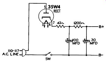
Figure 32. A Power Supply Circuit Common to Transformerless Receivers.
Now, the question can be raised, "How does the set operate under these conditions?" The set does operate, we know, and the answer is to be found in the fact that when the energized wire becomes negative, the grounded wire is, by comparison, more positive. Since the rectifier tube is concerned only with the relative voltage between these two wires, it will conduct during this half cycle.
Thus, to the receiver itself, it makes no difference which power wire connects to B- and which goes to the rectifier tube.
Suppose, however, that the receiver B- is also connected to its chassis (which is frequently true) and that this chassis is resting against the electrical conduit pipe running along the bench. Since the pipe is at ground potential, one of two things can happen.
1. If the grounded wire of the power line connects to the receiver B-, then nothing will happen.
2. But if the energized wire of the power line is the one that reaches the receiver chassis, then you will be shorting this wire to ground.
Result: A surge of current and one blown fuse. The blown fuse is readily replaced but the surge of current may easily damage the receiver On-Off switch and burn out pieces of metal on the receiver chassis or the conduit pipe.
Instead of backing the receiver up against the conduit pipe, suppose we connect a VTVM to the receiver for a series of voltage measurements. The common or ground lead of the VTVM goes to B-, while the voltage probe is placed at various points to determine the various potentials. Here, again, we have several interesting situations which can arise.
If neither the receiver nor the VTVM chassis (and cabinet) come in contact with any ground conductor, nothing will happen. But if either of these units does make contact with a power line ground and the energized power wire is connected to the receiver B-, the fuse blowing fireworks discussed will occur, this time with possible damage to the VTVM, or whatever other instrument is employed.
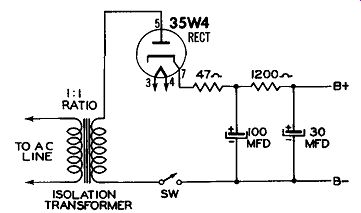
Figure 33. By Using an Isolation Transformer, There Is no Direct Connection
Between the Power Line and the Receiver.
To prevent shorting the power line to ground, a 1-to-1 isolation transformer should be inserted be tween the power line and the transformer less receiver. See Figure 33. The isolation transformer removes the direct connection between the power line and the receiver and now we can ground the receiver chassis without disturbing its operation or that of the power line.
In transformer operated receivers, isolation is achieved by the set transformer itself and so, of course, no additional unit is required.