INTRODUCTION
Despite the fact that television receivers contain broad bandpass circuits extending over a range of 3 to 6 mhz, the r e are a considerable number of applications to which an AM generator be put. Thus, an AM generator can be employed for peaking the various coils in stagger-tuned video IF systems; they can be used to align the audio IF circuits; and, finally, AM generators find extensive application as marker generators. In this latter capacity, the AM generator provides an identification signal ( or marker) which, when used in conjunction with a sweep generator, shows the operator the exact position of certain frequencies within the bandpass of the circuits under test. A complete and detailed discussion covering this very important application will be given in a later section.
The AM generator, whatever frequency range it covers, consists basically of an RF oscillator whose output frequency can be varied over a certain range. This signal is available as is (i. e., unmodulated) or it may be combined with a low-frequency audio signal (i.e., modulated). To achieve this amplitude modulation, the generator also includes an audio oscillator, operating at a fixed frequency which is usually in the neighborhood of 400 cycles. Provision is always made to bring the modulation in, when desired, or, to cut it off when only the RF signal (or carrier) is needed. For direct testing of the receiver's audio system, the 400 hz signal voltage is also available at a front panel jack.
AM GENERATOR CIRCUITRY
The complexity of the AM generator, like that of the VTVM, depends upon the number of functions which the unit is designed to perform. One of the simplest commercial units available (in kit form) is shown in Figure 1. V1 (a 6C4) is operated as a Hartley oscillator. The output of V1 is resistance coupled to a buffer tube, V2A. A four-step ladder attenuator and a variable potentiometer in the cathode circuit of the buffer stage control the output of the generator without loading the oscillator stage. (Loading changes in the most rigidly controlled oscillator will tend to cause a frequency variation.) The second half of V2 (V2B here), 1/2 of a 7F7 tube, is connected as a 400-cycle audio oscillator.
The modulated output then appears across the cathode of V2A, from which point it is fed to the output terminals of the signal generator.
Stability is all-important in any type of test instrument, and especially so in signal generators.
To achieve a measure of stability in the circuit shown, a voltage regulator tube is connected across the output of the power supply. With this regulator, line voltage variations from 95 to 135 volts will not affect the generator accuracy. However, variations in the value of the other oscillator components will have an affect on the frequency. Just how immune the oscillator is to component value variations depends upon the quality of the parts used, and frequently this varies in direct proportion to the price of the instrument.
AM signal generators are one of the oldest pieces of test equipment employed by the radio serviceman. That they are more complicated now is due principally to the extension of broadcasting into newer (and higher) frequencies. Thus, where pre war signal generators were required to generate signals extending only to the end of the radio broadcast band, now they must cover this range plus FM and television, too. This means an extension up to 220 mhz and, in time, even higher as the UHF bands are opened up to commercial broadcasting.
The front panel of the generator discussed in Figure 1 is shown in Figure 2. The dial face is seen to consist of a number of scales (here, 7), each scale devoted to a different set of frequencies. The lowest frequency scale is the outermost scale (labeled A). The frequencies across this scale range from 75 khz at the low end to 220 khz at the high end.
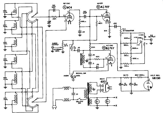
Figure 1. The Circuit Diagram of a Simple AM Generator.
At this point, one might raise the question, "How do you know that the outer scale concerns the lowest generated frequencies of this instrument?" And furthermore, "How do you know that the frequencies are in kilocycles ?”
Both are very pertinent and very legitimate questions that might be asked by any serviceman -- especially one whose experience with signal generators is limited. The answer to both questions will be found in the instruction booklet which is supplied with every test instrument. In some instruments, as we shall see later, sufficient information is given on the face of the dial to enable the user to determine the frequency coverage by inspection alone. In other instruments, such as the one pictured in Figure 2, recourse to the instruction booklet is necessary.
One point worth noting about most signal generators is this. When the different scales are identified or labeled by letters of the alphabet, such as A, B, C, D, etc., then almost without exception the lowest frequency scale is assigned the lowest letter.
Continuing with the scales shown on the AM generator of Figure 2, the second or "B" scale covers the frequency range from 200 khz to 600 khz. A comparison of this range with that of scale "A" reveals that the low end of scale "B" overlaps the high end of scale "A". In other words, a portion of the highest frequencies reappear at the low end of scale "B". This is another common pr act i c e and is done to insure that the rise in frequencies is continuous. If the beginning of scale ."B" started just at the end of scale "A", it might happen under some circumstances* that the frequencies generated by the instrument for scale "A" did not quite extend up to the highest frequencies indicated on that scale. This would cause a gap to appear between A and B and impair, to some extent, the usefulness of this generator. It is to pre vent this from happening that the frequency ranges of the various scales overlap.
The range of the third or "C" scale of the generator extends from 550 khz to 1700 khz. Writing 1 700 khz in mhz produces a result of 1.7 mhz. Scale "D" starts below this, at 1.6 mhz and rises to 5.0 mhz.
--------------
* A change in value of circuit capacitance, resistance, inductance, a variation in the operating voltages, or aging of the oscillator tube itself might readily alter the frequencies generated by an oscillator. Especially critical in this respect are the end frequencies of any resonant circuit.
---------------------
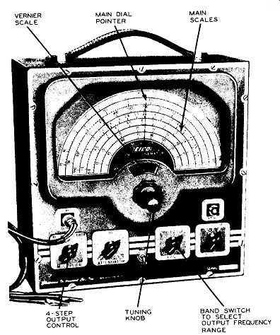
Figure 2. An AM Generator Available in Kit Form. Courtesy of Eico.
------------
Scale "E" ranges from 5.0 to 16 mhz. Next follows scale "F" with 10 to 50 mhz and finally scale "G" with 45 as the first number and extending up to 150 mhz.
While 45 is the first number on scale "G", actually the dial contains markings below this point. However, the section below 45 (on scale "G") need not be used since it repeats a portion of scale "F". The choice of a particular range is governed entirely by the switch marked " Band" located just below and slightly to the right of the dial knob. There is a separate position for band A, B, C, D, and E. Note, however, that bands F and G both occupy the same selector switch position. Also, if you look closely at scales F and G you will discover that every number on scale G is exactly 3 times the number appearing directly above it on scale F. This means that one tuned circuit is being used to generate all frequencies from 10 mhz on up. The basic or fundamental frequencies being developed by the generator ( with the "Band" switch in the F, G, position) are those indicated on scale F, namely, 10 to 50 mhz. However, as is true of nearly all oscillators, harmonics are generated together with the fundamentals. In this instrument we are interested in the third order harmonics. Note, however, that there are present also the second harmonics and possibly some fourth, fifth, and even higher harmonics, although the harmonic amplitude falls off quite sharply as the ha r mo n i c order rises.
The range, then, of the generator shown in Figure 2 extends from 75 khz to 50 mhz on fundamentals, and from 50 mhz to 150 mhz on harmonics. The practice of using harmonics for the higher frequencies is a commo n one since it is obviously more economical to use one . set of tuned circuits for two ranges than one. The disadvantage of this arrangement is the decrease in signal output for all harmonies. Thus, the strength of the "G" scale signals will be less than those of scale "F" and might prove difficult to work with. Also, by using harmonics it is possible that spurious signals, caused by the beating of one frequency against another, will develop which will give false indications in the circuit you are working with. With careful design, how eve r, these disadvantages can be minimized (and are) to the point where the majority of present day AM generators develop their highest frequencies harmonically and little difficulty is encountered in normal operation.
VERNIER SCALES
The graduations on the various scales of the generator dial are simply designed and if you apply. the rules established in Section 1 for reading VTVM scales, no difficulty will be encountered. Generator dials are seldom as complicated as VTVM scales.
There is, however, one feature concerning these dials that differs considerably from anything that has been previously encountered in vacuum-tube voltmeters. This feature is the use of an auxiliary vernier scale in conjunction with the generator dial.
Now, by definition* a vernier is an auxiliary scale containing slightly smaller divisions than the main scale, and by means of which readings may be made with greater precision than allowed by the main scale.
On the generator shown in Figure 2, the vernier scale is located just above the dial knob. When the knob is rotated, it moves the main dial pointer across the scales; at the same time the vernier scale contains a greater number of divisions per inch and hence, for a given rotation of the knob, more divisions are covered on the vernier scale than on the main dial. And because of this, it is possible, as we shall see, to determine readings on any of the main scales to a greater degree of accuracy than if there was no vernier.
In Figure 3 two scales are shown. Scale A, the main scale, has 7 divisions while scale B, the vernier scale, has 21. As the pointer moves from 0 to 7 on scale A, it will travel from 0 to 21 on scale B. Furthermore, since both scales are linear, the 21 vernier divisions will be divided evenly between the 7 divisions of scale A. This means that as the pointer moves from 0 to 1 on the main scale, it will move from 0 to 3 on the vernier scale. (Another way of stating the same facts is to say that each vernier division is equal to 1/.3 division on the main scale.) Now, as long as we desire to deal only with the whole numbers on scale A (such as 1, 2, 3, 4, etc.) and we can set the pointer precisely on each major mark, then the vernier scale will be of little use. But when, as is frequently the case, we wish to set the pointer to some position between whole numbers, then the vernier scale comes in very handy.
----------------
* As given in "A Dictionary of Electronic Terms," published by the Allied Radio Corporation of Chicago.
----------
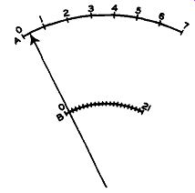
Figure 4. The Vernier Scale "B" Helps to Set the Pointer to a Desired
Point on Scale "A". To illustrate, suppose we desire to set the main
scale pointer to .33. This point, we know, is one-third of the distance between
0 and 1 and, more frequently than not, we would be wrong. We may not be very
far wrong, but the chances are good that we would be off to a certain extent.
However, with the help of the vernier scale, we can actually hit .33 right
on the head. For when we move the pointer from 0 to 1 on the main scale A,
we go from 0 to 3 on the vernier scale B. This means that when we move the
pointer on the vernier scale to 1, the pointer on the main scale is at .33.
See Figure 4. Since we can hit 1 on the vernier scale quite accurately, we
can reach .33 on the main scale just as precisely.
Continuing, when the pointer is directly at line 2 on the vernier scale, it is at .66 on the main scale.
And, finally, when the pointer is at 3 on the vernier scale, it is at 1 on the main scale.
Thus, we see that with the help of the vernier scale, we· can obtain many more accurate readings on the main scale than we could have without this additional scale, other points than those discussed may also be determined more accurately with the aid of the vernier scale. For example, suppose we wish to set the pointer to .5. This point is approximately mid way between .33 and .66 and by setting the pointer midway between lines 1 and 2 on the vernier scale we can come quite close to the .5 position. Certainly we can more closely approximate .5 on the main scale by using the vernier than we could be relying on scale A alone.
One fact made evident by the foregoing discussion is that the more divisions the vernier scale possesses (over a given section of its scale), the more accurate will be the settings made on the main scale.
We are now in a position to consider vernier scale usage in more specific terms. Thus, in Figure 2, suppose we wish to obtain a signal having a frequency of 145.6 khz. This would lie on scale A between 140 and 150 khz. To determine where 145.6 exists as closely as possible, set the pointer first on 140 khz and note the reading on the vernier scale. In this case let us say it is 73. Next, rotate the knob until the needle is at 150 khz on scale A. Again note the reading of the vernier scale. At this point it is 99.
We see, then, that for a variation of 10 khz (150 khz - 140 khz), the vernier moved 26 divisions (99-73) past its reference hairline. If we divide the 26 into the 10, we obtain an answer of .384. This means that every division of the vernier equals .384 khz on scale A. Thus, if we move the vernier from 73 to 74, we change the generator output frequency from 140 khz (at 73) to 140.384 khz (at 74). To reach 145.6, we have to increase the generator frequency 5.6 khz above 140 khz. Since each vernier mark is equal to :384 khz, what we have to determine is how many times does .384 go into 5.6.
This will tell us how many divisions to move the vernier scale past 73. Performing the division (i. e., 5.6 .384) gives us an answer of 14.6. And so, if we add 14.6 to 73 (our starting point or 140 khz), we set the vernier dial to read 73 + 14.6 or 87.6, the signal generator will be developing an output frequency of 145.6 khz.
It should not be supposed that the value of .384 khz per vernier division holds true at all points on scale A. It would hold true if scale A were perfectly linear and if the vernier scale were likewise perfectly linear. Since this is seldom true, it is best to go through the same procedure for each different section of every scale. In this way you will be certain of approaching as close to the desired frequency as possible.
OTHER GENERATOR CONTROLS
In addition to the "On-Off" switch and the "Band" switch which we have previously considered, there are three other controls and two signal outlets on the generator of Figure 2. One control, the "Multiplier," is a four-way selector switch serving to regulate, in four steps, the intensity or amplitude of the signal delivered by the generator. In the X1000 position, the maximum amount of signal is available at the "RF Output" terminal located just above this control. In the Xl00 position, approximately 1/10 th as much signal is permitted to reach the output terminal, the remainder of the signal being dissipated in resistive attenuation pad. See Figure 1. In the X10 position, the signal level is still further decreased, and in the X1 position it is at its lowest point.
In each of the four positions, the level of the signal may be continuously varied by means of the "Attenuator" control. This type of arrangement provides full control of the signal from maximum to minimum.
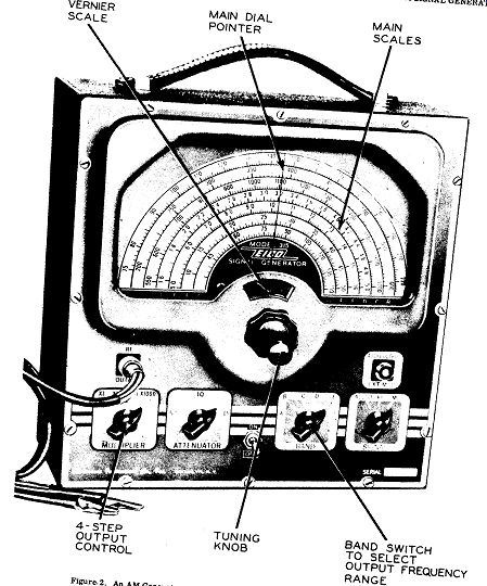
Figure 2. An AM Generator Available in Kit Form. (Model 315, Courtesy of
Eico.)
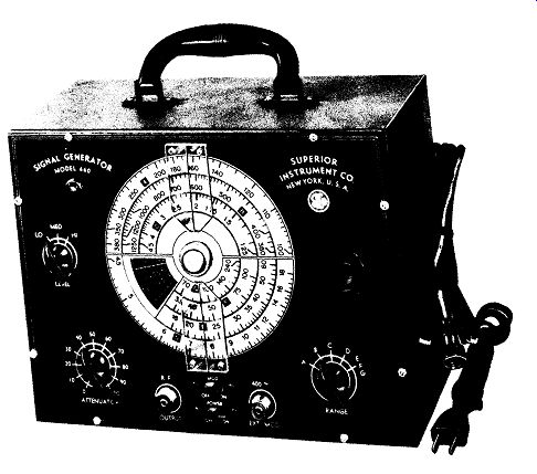
Fig. 5. A sig. gen with range 100 khz to 240 mhz. (Model 660, courtesy of
superior instrument Co.)
On the other side of the panel there is a "Signal" control possessing three positions: Audio, wherein the audio signal ( 400-cycles) is made available at the "Audio Output" terminal; RF, when only an unmodulated RF signal appears at the "RF Output" terminal; and "Mod," when the RF signal at the "RF Output" terminal is modulated by the audio note.
Control of the amplitude of the audio signal at the "Audio Output" terminal is also achieved by rotating the "Attenuator" control. This knob attaches to a dual potentiometer, one section of which serves for the RF signal, and one for the audio signal.
To obtain the signal voltages present at either the "RF Output" terminal or the "Audio Output" terminal, a coaxial cable is provided with the instrument.
One end of the cable screws on to the output terminals while the other end contains two alligator clips. One clip attaches to the other conductor of the cable and represents the ground output connection of the generator. The other clip connects to the inner conductor of the cable and is the one which is usually referred to as the "hot" lead since it carries the signal.
While most generators - in common with this one - contain an internal audio oscillator whose output can be used to amplitude-modulate the RF sign a 1, provision is also made to permit modulation by an external signal, if this is desired. In the instrument shown in Figure 2, the external modulating voltage is fed into the instrument at the "Audio Output - Ext.
Mod." terminal. The "Signal" control is placed in the RF position to disable the internal audio oscillator and prevent it from feeding its signal to the buffer tube at the same time.
USE OF THE AM GENERATOR
To place the AM generator of Figure 2 into operation, it would be connected to the nearest AC outlet and the "On-Off" switch flipped to the "On" position. The instrument should be permitted a period of 10 to 15 minutes to war m up and in the meantime its various controls can be set to position.
Initially the "Multiplier" control is switched to the X1000 position; and the "Attenuator" knob set any where from mid to maximum clockwise position. The "Band" switch would be set to the range which contained the desired frequency and the "Signal" control would be positioned either at "RF" or "Mod" depending upon whether an unmodulated or a modulated signal was desired. Finally, the dial would be set to the frequency required and possibly, as a last step, the coaxial cable connected to the "RF Output" terminal. When the 10 or 15 minutes have elapsed, the instrument is ready for use.
Those men who have had extensive experience with generators of this type will recognize that the foregoing sequence may be varied by the individual as he sees fit. Actually, the sequence given is merely to indicate a method of preparing this instrument for use and is not to be construed as the only method.
Once the generator is connected to the receiver and the signal modulation is either being heard or observed on an indicator (such as an oscilloscope or VTVM), then the "Multiplier" and "Attenuator" controls are adjusted for the 0 desired signal output. If the generator is being used for signal tracing purposes, then it is customary to use a moderate to strong signal output. On the other hand, if the generator is being used for alignment, the controls are set as low as it is possible to place them and still obtain an indication from the receiver. Never over drive a receiver being aligned because any adjustments made under these conditions will not provide maximum sensitivity when the set is used to receive weak or moderate signals. We will return to this point again (and again) in a subsequent section covering the application of generators in FM and TV receiver alignment.
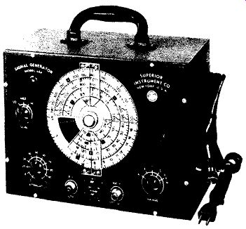
Figure 5. A Signal Generator With a Range From 100 khz to 240 mhz. Courtesy
of Superior Instrument Co.
If it is desired to employ the generator for audio alone, the "Signal" switch is set to "Audio." The coaxial cable connected to "Audio Output-Ext. Mod." adjust "Attenuator" for desired output (revealed by audio note heard, or the level developed on your oscilloscope or VTVM). None of the other controls have any effect on the audio output signal.
The front panel of another AM signal generator is shown in Figure 5. The frequencies covered by this instrument extend from 100 khz to 240 mhz in seven (A, B, C, D, E, F, G) ranges. Not only is each of the scales identified by a letter, but also the frequencies for that range. To select the desired band of frequencies, there is a "Range" switch in the lower right-hand corner of the front panel. Note, however, that bands E, F, and G are all obtained at the same switch setting indicating that all frequencies beyond the fundamental range (18-60 mhz) of band E are harmonics. For band F the second harmonics are utilized and for band G, the fourth harmonics. The instrument output will thus be expected normally to decrease as you go from scale E, to F, to G. Two hairline indicators are used because the dial plate only rotates for 180° and whatever is on the bottom half of the plate (bands D, E, F, and G) cannot pass underneath the top hairline indicator. The top indicator is thus used with bands A, B, and C while the bottom reference line deals with the remaining four ranges. Also, because of this arrangement, frequency on the top three scales increases from right to left while on the lower scales the frequency rises from left to right.
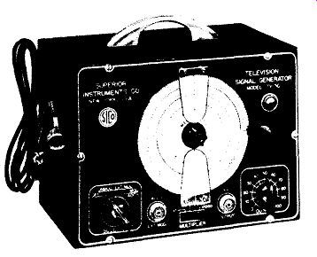
Figure 6. A Signal Generator Especially Designed for Television Service Operation.
Its Range of Frequencies Extends From 18 to 250 mhz. Courtesy of Superior Instrument
Co.
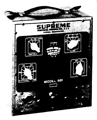
Figure 7. A Supreme Model 661 AM Signal Generator.
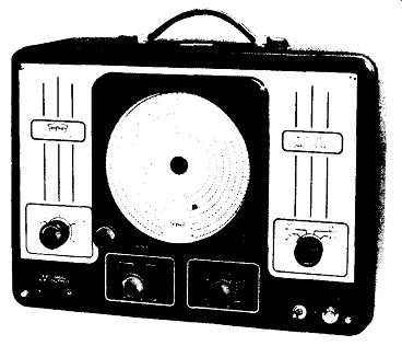
Figure 8A. A Signal Generator Which Will Generate Frequencies up to 120 mhz.
The Range Selector Markings Extend Only to 40 mhz, but by Means of Harmonics,
120 mhz can be Obtained. Courtesy of Triplett Electrical Instrument Co.
The other controls on this generator are self explanatory and should cause no difficulty. The "Level" control, instead of being calibrated in terms of X1000, X100, X10, and X1, as in the previous generator, now contains the markings of Lo, Med, and Hi. A continuously variable potentiometer labeled "Attenuator" permits control of the signal level out put for each position of the "Level" control.
Available, too, are "Mod" On-Off switch, a power switch, and two signal output connectors. The knob to turn the large dial plate is located at the right.
The instrument in Figure 5 can be employed for AM, FM, and TV receivers. For those shops which devote most of their time to television sets, a special signal generator developing only frequencies from 18 to 250 mhz is made available by the same company. This unit is shown in Figure 6. The control marked "Output" in the lower right-hand corner of the panel regulated the level of the output RF signal. It serves the same purpose as the knob labeled "Attenuator" in Figure 5. A four position switch marked "Multiplier" performs the same function as the "Level" control on the signal generator of Figure 5.
It is interesting to compare these two instruments and note the differences in the labeling of controls which perform the same functions in their respective units. This in spite of the fact that both units were designed by the same manufacturer. There is no standard nomenclature for instruments doing similar jobs although it is true that most differences in control labeling can be resolved with a little study.
A simplification in dial markings is achieved in the signal generator shown in Figure 7. The dial is mounted behind the front panel and only a small section of it is visible at any time. Two scales take care of five bands, (A) 65-205 khz (B) 205-2050 khz (C) 650-2050 khz (D) 2050-6500 khz (E) 6.5-20.5 mhz and the reason this can be done can be seen from an inspection of the above frequency arrangement.
Three of the bands (i.e., A, C, and E) are multiples of each other permitting the use of one scale ( with the appropriate mental multiplication) for all three.
The other two bands, B and D, can both be accommodated on another separate scale by the same arrangement.
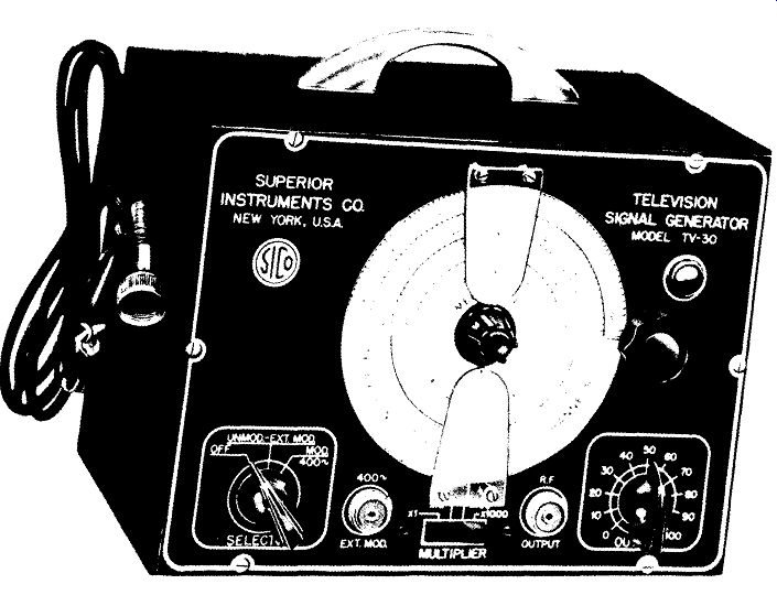
--- Figure 6. Extends from 18 to 250 m,. (Model TV-30, Courtesy of Superior
Instrument Co.)
Figure 8A. A Signal Generator Which Will Generate Frequencies up to 120 mhz. The Range Selector Markings Extend only to 40 mhz. But by Means of Harmonics 120 mhz Can Be Obtained.
(Model 3432, Courtesy of Triplett Electrical Instrument Co.)
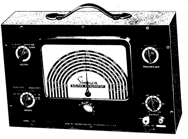
Fig. 8B. A Simpson Model 340 Signal Gen.. (Simpson Electrical Instrument co.)
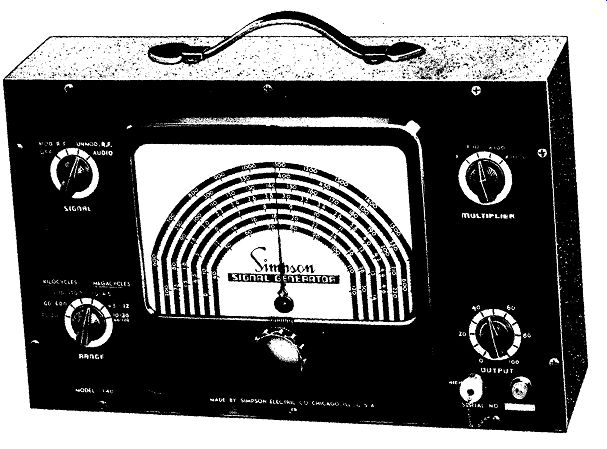
Figure 9. The Precision Model E-200C Signal Generator. The RF Attenuator Controls
Are Both Continuously Variable. This Is a Departure from the Previous Instrument.
(Courtesy of Precision Apparatus Company, Inc.)

Figure 8B. A Simpson Model 340 Signal Generator. Courtesy of Simpson Electrical
Instrument Co.
Two additional signal generators are shown in Figures 8A and 8B. Both units contain controls which are similar in name and functions to the controls on the AM generators just discussed. In Figure 8A the "Int. Mod" position of the "Circuit Selector" switch refers to the modulation which is applied to the RF signal by the instrument's own audio oscillator. This position is usually referred to as "Mod RF" rather than as "Int. Mod. "
MORE ELABORATE AM GENERATORS
The foregoing analysis has dealt with those controls which are basic to all signal generator s without regard to their cost. On more elaborate units additional controls and connector terminals will be found, enabling the instrument to perform a wider variety of jobs.
As an illustration, consider the AM signal generator shown in Figure 9. Some of its controls, such as the "Band Selector," the four position selector switch at the right, and the center dial are immediately recognizable. The RF output connector terminal uses a coaxial cable, while the audio signal is obtained from a pair of pin jacks at the right. In place of the four position "Multiplier" control used in Figure 2, this instrument has a continuously variable potentiometer labeled "RF Control - 1." Then, for any setting of this control, "RF Control - 2" permits the operator to take all of the RF signal offered or any portion of it. In other words, "RF Control - 2" is identical in its function to the "Attenuator" control of the previous signal generators. The RF output signal may be obtained at one of two terminals. One terminal, at the left, is marked "Low;" the other, slightly to the right of it, is marked "High." The RF signal is available at both connectors, except that the amplitude is somewhat lower at the "Low" terminal than at the "High" terminal, due to the presence of a 4,000-ohm resistor in the· line leading to the "Low" connector. The manufacturer recommends the use of the "Low" terminal at all times except where the circuits are misaligned and the maximum signal from the generator is required. A screw-cap allows shielding of the unused terminal to minimize signal leakage from this source.
At the opposite (right-hand) side of the instrument panel there is a "Mod Control" with which the intensity of the audio signal can be varied from zero to maximum. It is called a modulation control because by regulating the amplitude of the audio voltage, it will regulate the extent to which the RF carrier is modulated. The greater the degree of modulation, the louder will be the audio output from the circuit under test.
Another feature of this instrument which has not been encountered in previous signal generators is the "AVC Control!' and the two pin jacks marked "AVC Voltage" - and+. The purpose of this arrangement is to make available a DC voltage which can be applied to a receiver being aligned. The voltage itself is obtained from the two pin jacks while its amplitude can be varied by means of the "AVC Control" potentiometer located just above it.
Normally, when a set to be aligned possesses AVC, it is necessary to keep the injected signal voltage low in order that the set does not develop sufficient AVC voltage to counteract the variations in output produced when the various circuits are tuned through resonance. It is, after all, the purpose of the AVC network to maintain the output of a receiver steady as the input signal varies. However, when we inject a signal for alignment purposes, we wish to observe just how the output varies as each tuned circuit is adjusted. To the A VC system, the variations produced by alignment have the same effect as varying the strength of the input signal and it reacts accordingly.
The result, with the AVC network in operation, is to broaden the response curve of the various tuned circuits, making it difficult (if not impossible) to achieve peak alignment.
The solution to this problem is either (1) to feed in so low a signal that the AVC action will be small or (2) to disable the AVC system and apply in its place a fixed DC voltage equal in value to the A VC biasing voltage developed with normal signals.
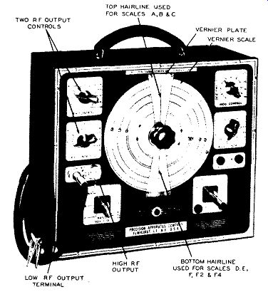
Figure 9. The Precision Model E-200C Signal Generator. The RF Attenuator Controls
are Both Continuously Variable. This Is a Departure From the Previous Instrument.
Courtesy of Precision Apparatus Co.
The first method is the simplest to perform and is widely used. Unfortunately, however, the alignment obtained by this method does not correspond exactly with the alignment of the receiver wider normal operating conditions and , consequently, the set is not actually adjusted for optimum operation under its normal operating conditions. The difficulty arises from the fact that when the grid bias of a tube changes, so does its input capacity. This capacity, in turn, parallels whatever tuned circuit is connected across the input of the amplifier stage, and as it changes in value, so does the resonant frequency of a tuned circuit. It is thus evident that for peak performance the tuned circuit should be aligned with a grid bias as close to the normal value as possible.
In recognition of these facts, a controllable DC voltage is made available at the front panel of the AM generator shown in Figure 9. The AVC line in the receiver is opened up and the DC voltage from the generator substituted in its place. The voltage is set at the value normally developed by the receiver AVC circuits and the set is aligned. The scale on the A VC control is calibrated to indicate the exact voltage appearing at the two A VC jacks.
SCALE CALIBRATION
This same generator ( Figure 9) has a vernier scale arrangement that differs from the vernier scale previously discussed in connection with the generator of Figure 2. Along the upper circumference of the dial there is a scale marked from 0 to 110. Directly above this scale, in the center of the instrument, is a s mall vernier plate* with markings from 0 to 10.
Through the use of this auxiliary plate, readings onto 0-110 vernier scale can be made accurately to tenths of one division. In other words, between 0 to 110 we can obtain 1100 readable points. And from our previous discussion we know that a vernier scale possessing 1100 readable points is cons id e r ably more accurate than a scale possessing only 110 divisions.
The manner in which the vernier scale and the vernier plate above it are utilized can be seen from the following discussion. Let us suppose that the vernier scale is so set up that the number 40 is directly underneath the 0 of the vernier plate. Then it can be seen from Figure 10 that none of the other vernier plate markings are directly over a division on the vernier scale except number 10 on the vernier plate.
---------------
* Note carefully this distinction between the small vernier plate and the larger vernier scale.
---------------
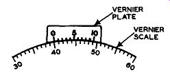
Figure 11. The Vernier Scale Reading Is 40.1.
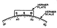
Figure 10. The Reading on the Vernier Sc ale in its Present Position is 40.
This Is True Because the Zero on the Vernier Plate Is Directly over the 40
on the Vernier Scale.
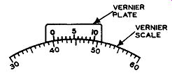
Figure 12. The Vernier Scale Reading is 40.2 Because Only the Two (2) Mark
on the Vernier Plate Is Directly Over a Vernier Scale Division.
------------------------
And if you look closely you will see that this 10 on the vernier plate coincides with 49 on the vernier scale. In other words, 10 vernier plate divisions are exactly equal to 9 vernier scale divisions. It is this particular relationship which enables the vernier plate to divide up each vernier scale division into ten equal parts.
Now, if you move the large vernier scale slightly to the left until the number 1 division on the vernier plate is directly over one of the vernier scale divisions - as shown in Figure 11 -- then you will not ice that the 0 of the vernier plate is just slightly beyond the number 40 on the vernier scale below it. To be exact, the vernier scale is now set at 40.1.
Next, move the vernier scale again slightly to the left until the number 2 division of the vernier plate is directly over a division on the vernier scale.
If you now examine the point where the 0 of the vernier plate is with relationship to the vernier scale beneath it, you will see that it appears as shown in Figure 12. The 0 of the vernier plate is now at 40.2 on the vernier scale.
It is interesting and important to note from Figures 11, 12, and 13 that one and only one vernier plate division can fully coincide, at one time, with a vernier scale division except for the extremes of zero and 10. In Figure 11 only the number 1 vernier plate division coincides with a scale division beneath it and consequently the decimal to be added to 40 (in this case) is .1. The full reading then become s 40.1. In Figure 12, only the number 2 vernier plate division coincides with a scale division beneath it and now the decimal to be added to 40 is .2. The full reading then becomes 40.2.
We can continue moving the large vernier scale slowly to the left (or counterclockwise) and if you watch the vernier plate you will see the number 3 division coincide with a vernier scale division, then the number 4 vernier plate division, etc., until the zero itself passes directly over the 41 marking of the vernier scale. The dial reading at this point would be 41.
This same procedure can be employed at any point along the 0-110 vernier scale with the result, as stated previously, that we can obtain 1100 readable points. It is necessary only to remember to look along the vernier plate and locate that division which most completely coincides with (runs into) one of the dial divisions directly below it. If this number hap pens to be the sixth line of the vernier plate, then we add 6/10 to that division on the vernier scale which is to the left of the zero line of the vernier plate. In the above illustrations, the number 40 was the one to which the .6 would be added. However, the vernier plate could be used in conjunction with any division of the vernier scale.
Once you become familiar with the use of the vernier scale on this instrument, you can use it with any frequency scale, A, B, C, D, E, F, F2, and F4.
An example will serve to illustrate the method.
Suppose it is desired to obtain an output frequency of 716 khz. Reference to the dial plate reveals that this frequency is on band C. Setting the "Band Selector" switch to band C, we rotate the dial until the 710 khz line is directly underneath the top hairline.
The vernier scale would then be read and it might be 38.2. (Note that the vernier scale is not read with reference to the hairline used by scale C but, instead, read with reference to the zero line on the vernier plate. This is important and must be observed, otherwise the vernier plate is useless.) Scale C would now be turned until the 720 khz line was directly underneath the top hairline. The vernier scale would again be read and its value might be 40.1. This means that for a change of 10 khz on scale C, the vernier scale ( with the help of the vernier plate) changed 40.1 - 38.2 or 1.9 divisions.
Dividing the 10 khz into the 1.9 divisions tells us that for each khz at this point on scale C, the vernier moves .19 divisions. Hence for 6 khz, the vernier scale would have to move .19 times 6 or 1.14 divisions. Since the vernier scale was 38.2 at 710 khz, if we add 1.14 to it (for a total of 39.34), the dial would be at 716 khz, which is what we want. Hence the vernier scale would be set to 39.3 and the job is completed. (The 39.34 is converted to 39.3 since we cannot set the vernier scale to any value closer than this. Had the number been 39.35, the setting would have been 39.4.) The same vernier scale would be used for bands D, E, F, F2, and F4 on the bottom half of the dial plate except that for reading the frequencies on these scales, the bottom hairline is used. Otherwise the procedure is exactly as outlined above. Thus, to obtain an output of 33.7 mhz, we would first set scale F2 so that the 33 mhz line was underneath the bottom hairline marker. Then the vernier scale reading would be noted. Next, the F2 scale would be moved until the 34 mhz mark was directly underneath the hairline and the vernier scale reading again noted.
Seven-tenths of the difference between these two vernier readings would lead us, as before, to the correct vernier setting in order to obtain an output frequency of 33.7 mhz.
It is also possible to reverse the foregoing procedure to set the dial according to a given frequency. Thus, suppose you know from past experience that when the vernier scale is set at 34. 7 and the "Band Selector" switch is set for the "A" band, that the output frequency is 109.95 khz and you wish to set the generator so that this frequency is developed. To reach 34.7 on the vernier scale, move the dial until the 34 falls directly under the zero line of the vernier plate. Then watch the 7th division on the vernier plate as you slowly rotate the dial toward 3 5. When the 7th line on the vernier plate is directly over one of the dial divisions below it, stop, because at this point the vernier scale reading is 34.7.
CRYSTAL CONTROLLED AM GENERATOR
The AM generator s discussed thus far are typical of the majority of such units which are avail able to the radio or television serviceman. However, for certain applications, where signals possessing crystal accuracy are desired, or where it is necessary to know the level of the output voltage, a generator such as shown in Figure 13 can be obtained. This particular instrument provides RF signals from 125 khz to 120 mhz and from 150 mhz to 220 mhz, all on fundamentals. In addition, a crystal oscillator is included into which crystals between the ranges of 250 khz and 20 mhz may be connected. For use in the mobile band, extending from 152 to 162 mhz, special crystals ground to produce a specific frequency are available. All output voltages may be calibrated within the limits of one-half microvolt to 100,000 microvolts by means of a step and a continuously variable microvolt control.
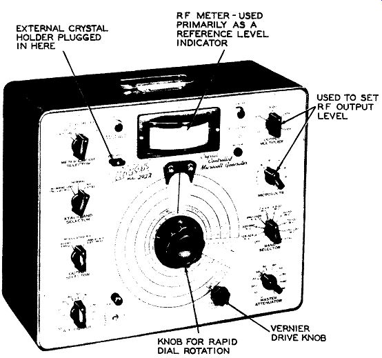
Figure 13. A Crystal-Controlled AM Generator. (Model 292X, Courtesy of Hickok
Electrical Instrument Co.)
In the center of the front panel there is a large frequency dial calibrated with the frequencies of the 8 bands covered by this instrument. The large dial plate may be rotated rapidly by using the center knob, or much more slowly by using a vernier drive (giving a reduction ratio of approximately 50 to 1) located at the lower edge of the main dial. The vernier drive may be disengaged completely from the main drive by pulling forward and rotating the knob.
Directly above the tuning dial is a meter with which the RF output may be calibrated. In addition, the meter also contains three db calibrated scales permitting it to be used as a 3-range decibel meter.
For this purpose the "Meter Circuit Selector" switch is turned to the desired db range and the signal is fed in at the pin jack on the panel labeled "Meter." Choice of the desired operating frequency is determined by the "Band Selector" switch. The last position of the switch, in the extreme clockwise position, is labeled "Int. Xtal." When the selector switch is in this position, output is obtained from the crystal oscillator. Either an external crystal (between 250 khz and 20 mhz) is plugged into the "Ext. Xtal" socket on the panel of the instrument, or a special crystal unit (for the 152-162 mhz band) would be connected internally in the generator.
All RF signal output ( including that derived from the crystal oscillator) is taken from the "RF Output" jack, Control of the amplitude of this signal is achieved by three controls: "Master Attenuator," "Microvolts," and "Output Multiplier." The "Master Attenuator" is adjusted with the meter is positioned at the proper reference point on its scale. (This in formation is contained in the instruction booklet that comes with the instrument.) Having done this, the settings of the "Output Multiplier" and "Micro volts" controls will then give the amplitude of the signal directly. For example, if the "Output Multi plier" control is set in the x 1 position, and the 0-10 dial on the "Microvolts" control is at 6, the generator output will be putting out 6 x 1 or 6 microvolts.
On the left-hand side of the panel, there is an audio output control which regulates the amplitude of the audio voltage obtainable from this instrument.
This control also has ganged to it an On-Off switch.
An "Output Selector" determines the type of signal made available by the unit, whether it be audio, pure RF, or modulated RF. The "Xtal-Band Selector" switch is in the normal position when the generator is required to develop signals having frequencies from 125 khz to 120 mhz (bands A through G). For the H-band, 150-220 38 mhz, the switch is turned to the left. And when the crystal oscillator is to be used, the switch is turned to the "Int. Xtal" position.
A standby-operate switch enables the operator to keep the tube filaments lit, but with no B+ voltages applied to the circuits. The instrument is now in the standby position. In the operate position, the B+ voltages are activated and the instrument is ready for use.
The foregoing brief discussion of the instrument shown in Figure 13 will give you some idea of how such a unit would be employed. Actually, to obtain full benefit of all its facilities, the operating instruction manual would be required.
The instruments which have been discussed and illustrated in this section do not represent all such units commercially available. They are merely representative of the type of generators the serviceman is most likely to encounter. However, if the purpose of each of the various controls discussed is understood, then little difficulty should be encountered in dealing with other AM Generators.
Thus far we have not discussed application of the various instruments either in television or tele vision alignment. This will be reserved for later sections, after additional test instruments have been described.