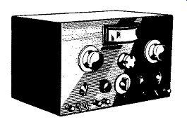
WHY SWEEP GENERATORS?
For many years, the favorite test instruments of the radio serviceman were the multimeter (VTVM or VOM) and the AM signal generator. With these he could perform any service task required - from the tracking down of a defective component to the complete alignment of a receiver. Other instruments were available but for many service shops these were considered as nice to have but not absolutely essential.
With the advent of FM and television, the serviceman found that his basic instruments now had to be expanded to include a sweep frequency generator and an oscilloscope. Where previously these two additional instruments were useful but not essential, now they assumed an importance equal to that of the multimeter and the AM generator.
To understand the reason for this change we must turn to the newer FM and television circuits and compare them with AM receiver circuitry. Actually, to get at the real reason for the change we should go back to the broadcast station itself. A receiver is nothing more than a device which converts the transmitted signal back to its original form, be it speech, music, or a picture. Hence, the basic design of the receiver is established by the transmitter.
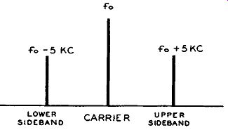
Figure 1. A Signal Which Is Broadcast by an AM Radio Station can Occupy a
Maximum Band Width of 10 khz.
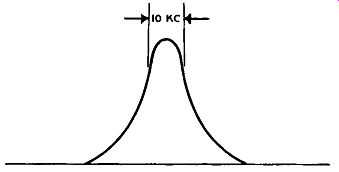
Figure 2. A Typical Response Curve of AM Radio Receiver.
----------
* FCC regulations permit use of audio modulation frequencies up to 7.5 khz which results in a maximum bandpass of 15 khz. However, if frequencies this high cause interference to other stations, the range must be reduced, generally down to 5 khz.
-------------
The signal which is broadcast by an AM radio station usually is restricted to a bandwidth of 10 khz.* Half or 5 of this 10 khz are above the station's carrier frequency and half below. See Figure 1. (The same information is contained in both halves (or sidebands) of the signal, and one sideband could be dispensed with. However, to do this would complicate the circuitry of the receiver and the transmitter and is not economically desirable.) The response curve of the receiver's tuned circuits, in order to receive this signal, possesses the shape shown in Figure 2. The received signal is centered about the peak of the curve where it receives the maximum amount of amplification. While the amplification at this point is not absolutely uniform, as it should be, its variation in the immediate vicinity of the peak is sufficiently small to be unimportant in most instances.
The AM broadcast band extends from 550 khz to 1700 khz (approximately) and when we compare 10 khz to these values (550 khz, 1700 khz, or any intermediate frequency), we see that it represents but a small portion of the carrier frequency. Because of this and because the response curve is symmetrical, simple tuning circuits can be employed in the receiver.
Satisfactory alignment can be carried out by feeding in a single frequency signal and peaking each tuned circuit for maximum response on a VTVM. In FM receivers, the situation is altered some what for several reasons. First, an FM signal occupies a bandwidth of approximately 200 khz which is 20 times wider than that required by an AM signal.
Secondly, FM IF amplifiers make use, from time to time, of double-peaked transformers and for optimum results the alignment of these circuits should be carried out visually. Finally, the response of an FM detector possesses a special shape (i.e., an S-curve) and this, too, should be "seen" to determine whether it possesses the proper linearity.
It is possible to align FM receivers using only an AM generator and a VTVM, in spite of the wider bandpass of the circuits, but visual alignment is recommended.
We come now to television receivers and to fully appreciate their requirements, let us examine the signal which is transmitted by the broadcast station. This is shown in Figure 3 for channel No. 2, 54-60 mhz. The television signal, complete, consists of a video portion and an audio portion. The video portion extends roughly for 5.25 mhz while the audio occupies a bandwidth of slightly less than 50 khz.
However, the combination of the two plus the spacing between the video and the audio signals results in a bandpass of 6 mhz. Thus, where the RF stages of a radio receiver are required to handle only 10 khz and the RF stages of an FM receiver must deal with 200 khz, the input section of a television receiver finds it self faced with a signal 6 mhz wide.
This is still not the full story on television receivers. In the video IF section of the TV receiver, it is important that the proper bandwidth (3.5 mhz to 4.0 mhz depending upon set design) be maintained and that the video carrier receive approximately half of the maximum amplification.
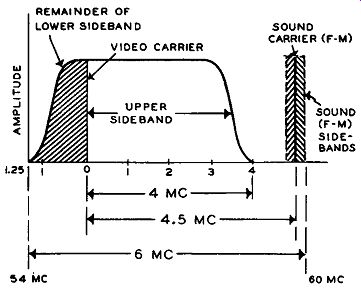
Figure 3. The Video and Sound Signals Broadcast by a Television Station. The
54-60 mhz Range Is That Allotted to Channel 2.
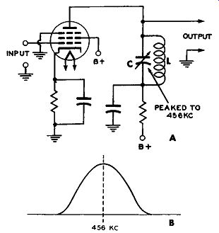
Figure 4. (A) A Simple Tuned Circuit LC, and (B) Its Response Curve.
Furthermore, the sound signal, if it is permit ted to pass through the video IF system (as in inter carrier sets), must be restricted to a certain level on the response curve. The criticalness of TV receiver alignment thus becomes evident, and this, coupled with the fact that the response curve is not symmetrical, Ieads to the necessity for aligning video circuits visually. With visual alignment you obtain a graphic picture of the circuit response as it is now, and by comparing the curve you see with the curve shown in the manufacturer’s service manual, you can tell immediately whether or not the system is aligned properly. If additional adjustments are required, these can be made on the spot and their effects will be at once apparent on the scope screen. Once mastered, this method of alignment can be performed in not much more time than it takes to align a radio receiver. This in spite of the fact that the bandpass of TV circuits is fully 400 times broader than radio circuits.
THE RESPONSE CURVE -- WHAT IT MEANS
A simple tuned circuit, consisting of a coil and a capacitor, will respond to different frequencies in the manner s how n in Figure 4. Let us assume that this resonant circuit is peaked to 456 khz. This means that if you apply a 456 khz signal to the grid of the tube, the resultant plate current that flows through the tube and the resonant circuit will develop more voltage across the tuned circuit than any other signal of equal input amplitude operating at some other frequency.
Another way of saying the same thing is to state that the impedance of L and C in Figure 4 is maximum at 456 khz. We can actually determine this by taking an AM signal generator and connecting it to the grid of the tube. To check the voltage which is developed across L and C, let us use a vacuum tube voltmeter having a high-frequency probe. We need this probe to measure voltages having frequencies of the order of 456,000-cycles.
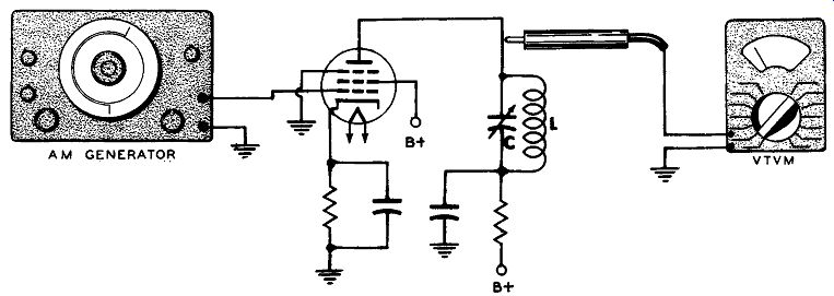
Figure 5. The Equipment Set Up to Obtain the Response Curve of LC.
The set-up of our apparatus is shown in Figure 5. The AM generator feeds its signal into the tube and the resulting plate current flows through the resonant circuit, Land C. We will assume that 1 volt of signal is applied to the tube for each different frequency to which we set the generator. This will cause the s a mhz amount of plate current to flow for each different signal. However, we will not develop the s a mhz amount of voltage across L and C because its impedance will vary with different frequencies and voltage is equal to impedance x current. Even though the plate current is the same for each applied frequency, the impedance of Land C is not and hence the voltage developed across Land C will vary.
We have now laid the groundwork for the plotting of the response curve of Land C point-to-point or rather, frequency-by-frequency. To start, let us apply a frequency of 456 khz to the grid of the tube and let us say that the VTVM indicates a reading of 1 volt across the LC combination.
Next, alter the frequency of the signal generator to 458 khz. If you look at the VTVM now, you will find that its reading is no longer 1 volt, but something slightly less, say .94 volts. What this means is that the impedance of L and C is not as high at 458 khz as it is at 456 khz.
If we c on tin u e to raise the frequency of the signal generator and watch the needle on the VTVM scale, we will find that it will move lower as the frequency rises. Points I through P_in the graph of Figure 6 show this. If we return h> 456 khz and then decrease the signal frequency gradually down to 446 khz, we will find that again the meter readings will decrease. This decrease is represented by points G through A in the graph of Figure 6.
Thus we find that the maximum voltage is developed across Land C at456 khz. At all other frequencies above and below this value, the voltage goes down.
Without disturbing the equipment set-up, let us attach a motor drive to the dial of the AM signal generator which will cause the dial to rotate from one end of the scale to the other. This, in turn, will vary the output frequency of the generator.
If the motor turns the dial very slowly, we will actually be able to w at c h the needle of the VTVM move back and forth in response to the changing voltages. However, just watching the motion of the needle will not help us develop a clear picture in our mind of how the circuit response varies.
A far better method of observing the complete circuit response can be achieved by replacing the VTVM with an oscilloscope. If the voltage that is developed across L and C is applied to the vertical...
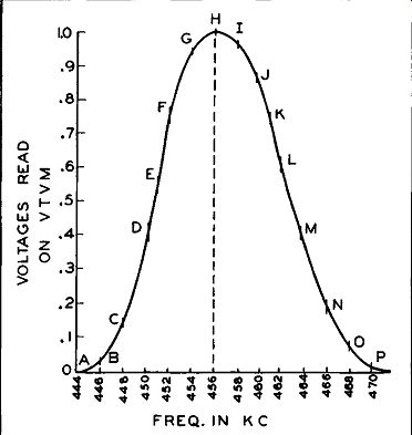
Figure 6. The Response Curve of LC in Figure 5 Obtained Point by Point. (For
the Sake of Simplicity, it Is Being Assumed That the Amplification of the Pentode
Stage in Figure 5 Is 1.)
...input terminals of the oscilloscope, you will see the entire response curve of L and C over the range of frequencies provided by the curve which we plotted so tediously point-by-point in Figure 6.
We could, if we wish, apply the same technique to a whole IF system rather than to a single tuned circuit. Again we would feed the signal in at one el).d and observe the voltage variation that appeared at the other end. The beauty of such an arrangement is that it permits us to see instantly what effect any one adjustment has on the overall response. Visual alignment is widely employed in television because the wide bandpass of video circuits rules out a point-to point alignment and because the placement of certain frequencies (such as the sound carrier or the video carrier) must occur at specific points on the response curve. It is only by means of the visual method that these points can be quickly and accurately checked.
SWEEP GENERATORS
In order to produce a response curve on the screen of the oscilloscope, it was necessary to attach a small motor to the generator dial. This may seem like a rather crude method for continuously varying the generator output frequency, yet the first sweep generators that we re manufactured contained just such a motor. However, instead of having the motor turn the outside dial, it was employed to whirl the rotor plates of a variable capacitor at a rate of 60 times a second or more. The rotating capacitor plates caused the generator frequency to vary and in this way frequency variation was achieved. In time more efficient methods were developed, the two now finding widest application be in g the reactance tube and an electro-mechanical arrangement using a speaker-like assembly.
The reactance tube method of obtaining frequency sweeping, or what is the same thing, frequency modulation is based on the fact that a tube and an appropriate electrical circuit can be made to appear as a capacitance or inductance to an electrical circuit.
And, if we apply a 60-cycle voltage to the grid of such a tube, the current through it will vary causing its capacitive (or inductive) effect to change at the same 60-cycle rate. By placing the reactance tube network across the tank circuit of an oscillator, we will pro duce a frequency variation. In the past, extensive use of this method was made in sweep generators. Within recent years, however, it has been largely superseded in popular-priced instruments by an electro mechanical method which is less expensive and which can produce wider sweeping ranges, when carefully designed. (Some difficulty is experienced on small frequency sweeps. Also, its moving parts are subject to wear and warping.)
In the electro-mechanical system of varying the frequency of an oscillator, a metal plate is positioned close to an oscillator coil and then the metal plate is alternately moved closer to and away from the coil. This mechanical movement changes the inductance of the oscillator coil and with it the oscillator frequency.
In the EICO sweep generator the oscillator coil consists of a specially designed flat open wound spiral coil embossed on a bakelite base plate. A flat metal membrane, which is mounted on the diaphragm of a speaker, is placed parallel to and very close to this coil. See Figure 7. When the speaker diaphragm is vibrated, the metal membrane moves with it, varying the inductance of the oscillator coil.
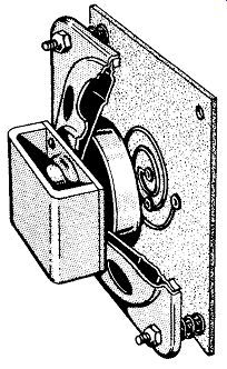
Figure 7. The Speaker-mounted Movable Membrane and Flat Oscillator Coil by
Means of Which Frequency Sweeping Is Achieved.
The extent of the frequency sweep is determined by the amplitude of the diaphragm vibration. This, in turn, depends upon the voltage applied to the speaker coil. The sweep rate is determined by the frequency of the voltage applied to the speaker voice coil and this is usually the same as the power line frequency (i.e., 60 cycles). Also, because use is made of the power line, the 60-cycle rate of variation is a sinusoidal one.
Now, so far as the operation of the sweep generator is concerned, it makes little difference whether the frequency varies back and forth sinusoidally or in some other fashion. However, sweep generators are invariably employed with oscilloscopes and to an oscilloscope the manner in which the frequency sweeps back and forth in the generator is most important.
Because of this, it may be desirable to review briefly the frequency variation in a sweep generator to see how this will affect the oscilloscope.
SINE WAVES
Almost everyone who has had any contact at all with radio is more or less familiar with a sine wave.
See Figure 8. For half of its cycle (ABCDE) the wave is positive and the current in the circuit to which this voltage is applied will flow in one direction. During the second half of its cycle (EFG HI), the voltage polarity reverses and with it, the current direction.
In examining this wave more closely, we find that it starts from zero (at point A) and increases in amplitude until a peak is reached at point C. Then it decreases in a similar manner until, at point E, it is back to zero again. From point E to point G the voltage rises again, this time in the negative direction until point G is reached. This is the negative peak.
Beyond G the wave drops back to zero, reaching this value at I.
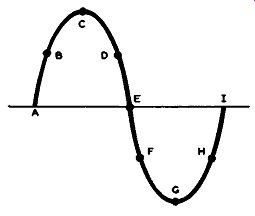
Figure 8. A Sine Wave.
If we apply this sine wave of voltage to a sweep generator, the output frequency will vary in a similar manner. See Figure 9. For the sake of this discussion, let us assume that at point A, when the sine wave voltage is zero, the generator is putting out a frequency of 25 mhz. Then, as the sine voltage rises to its p e a k (point C), the s we e p generator output frequency rises to a value of 27 mhz. From C to E, as the sine voltage decreases, the frequency of the sweep generator follows suit, dropping down from 27 mhz to 25 mhz.
From E to G, the sine wave dips into the negative half cycle and the output frequency of the sweep generator drops, in step, from 25 mhz to 23 mhz. Point G is the lowest point of the sine wave and from here to point I, the voltage returns to zero. In step with this, the frequency output of the generator rises from 23 mhz to 25 mhz. This sequence is repeated cycle after cycle for as long as the equipment is in use.
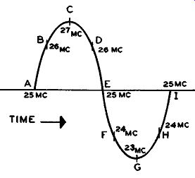
Figure 9. The Sinusoidal Change in Output Frequency of a Sweep Generator in
Which the Modulator Is Driven by a 60-cycle Voltage. (Whether the Output Frequencies
Increase on the Positive 1/l Cycle, as Shown, Depends on the AC Connections
to the Voice Coil of the Speaker driving Unit.)
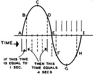
Figure 10. The Rate of Change Varies at Different Points on a Sine Wave.
Looking at Figure 9, we see that the center frequency of the sweep generator is 25 mhz. During one half cycle it rises to 27 mhz and during the following half cycle it decreases to 23 mhz. The sweeping range of the generator is thus from 23 mhz to 27 mhz, or, stated somewhat differently, it is 25 mhz :t2 mhz.
By changing the frequency of the sweep generator, we can r a is e or lower the center output frequency from 25 mhz to any other frequency which the unit is capable of developing. In fact, we will soon see sweep generators whose ranges extend from 500 khz to 220 mhz and more. Also, at many points, a sweeping range of as much as 15 mhz is available.
However, for simplicity of discussion, we will use the 25 mhz ±2 mhz mentioned above.
There is still another property of the sine wave variation which has not been discussed and this concerns the rate at w hi c h the frequency varies as it goes through one complete cycle. Let us return to Figures 8 and 9 and consider the positive half cycle ABCDE. The wave rises from A to B fairly rapidly.
We know this because the slope of the wave here is steep. From B to C and from C to D the wave amplitude changes much more slowly because to go from B to D takes four times as long as it does to go from A to B. See Figure 10.
From D to E the rate of change again becomes quite rapid because of the steep slope of the wave within this region. The rapid change is maintained until point F is reached.
From F to G to H the rate of change again slows down; in fact it takes just as long to cover this distance as it did to go from B to D and this should be so because FGH occupies the same position on the negative half of the sine wave as BCD on the positive half.
The final section of the curve, H to I, requires as much time to complete as it did going from A to B. This uneven rate of change throughout the sine wave cycle reflects itself in an uneven variation in frequency fr o m the output of the sweep generator.
Thus, in Figure 9, the output signal starts from 25 mhz and rises fairly rapidly to 26 mhz. From 26 to 27 mhz, the rate of change slows down and so the generator needs more time to cover the 1 mhz from 26 to 27 mhz than it did to go from 25 to 26 mhz.
The return from 27 to 26 mhz requires as much time as it did in going from 26 to 27 mhz. However, once past point D (26 mhz), the generator output rate increases and the swing through 26 to 24 mhz is accomplished in short order. From points F to G to H (24 to 23 to 24 mhz) a slowing down occurs again, just as it did at the positive peak. Finally, from H to I, or from 24 to 25 mhz, the rate of change increases again.
SWEEP GENERATOR AND OSCILLOSCOPE
With this understanding of how the frequency of the signal output of a sweep generator acts when it is varied in a sinusoidal manner, let us take this signal and apply it to an IF amplifier. The signal is fed in at the input end of the amplifier or system and the output is obtained at the other end and applied to the vertical input terminals of the oscilloscope. A detector is required between the output of the amplifier and the oscilloscope because the frequencies involved (24-26 mhz) are much too high to pass through the vertical amplifiers of the oscilloscope and also because we are not really interested in the frequencies themselves but rather what happens to their amplitude as they pass through the circuit under test.
A response curve of a circuit, such as the curve shown in Figure 11, tells us which frequencies the circuit allows to pass and which frequencies it attenuates. Thus, 25 mhz is permitted to pass through freely while 23 mhz and 27 mhz are greatly attenuated. Note, too, that there are other frequencies, such as 24 and 26 mhz here, w hi c h although they pass through the system, do not receive as much amplification as the 25 mhz signal.
While the frequencies as shown in Figure 9 may not occur at precisely the points shown, the rate of change as indicated in the discussion does take place and this is actually what the discussion is trying to emphasize.
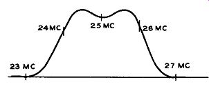
Figure 11. A Response Curve. See Text.
Now, assuming that the signals applied to the system to be tested are all equal in amplitude, we can see from Figure 11 that when they come out at the other end of the system, the 25 mhz signal will be stronger than either the 23 or 27 mhz signals. It is this change in amplitude that we are interested in showing on the scope screen.
When we pass a set of signals through a system and the amplitude of the signals change, then we can rightfully say that the signals have been amplitude modulated. And to obtain this modulation, or variation in signal amplitude, we pass the output signal through an AM detector.
This is the reason for inserting a detector between the amplifier and the oscilloscope as shown in Figure 12. The detector "skims off" the amplitude variation introduced by the system through which the signal has passed and then feeds this to the oscilloscope producing the response curve seen on the screen.
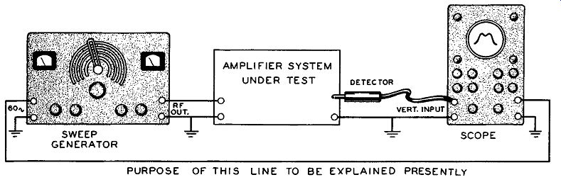
Figure 12. How to Connect Sweep Generators and Oscilloscopes to an Amplifier
System to Obtain Its Response Curve. See Text.
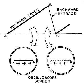
Figure 13. The Manner in Which the Beam on an Oscilloscope Screen Traces and
Retraces.
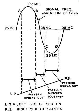
Figure 14. A Sinusoidal Frequency Variation, Coupled With a Linear Saw-tooth
Beam Motion, Will Produce a Pattern Bunched in the Middle and Stretched Out
at the Ends.
We have now progressed to the point where we can consider a statement made earlier in the discuss ion to the effect that the manner in which frequency is swept back and forth in the generator is important to the oscilloscope which must develop the response pattern.
In an oscilloscope, the electron beam starts at the left-hand side of the screen and moves toward the right at a constant rate. When it reaches the extreme right-hand side, it is rapidly returned to the extreme left-hand side from which point the same cycle of events recur. As the beam moves across the fluorescent screen of the oscilloscope tube, it leaves a bright green trace. If the forward motion of the beam recurs often enough -- say 40 times or more a second the brightness of the line will remain steady, without flickering.
This is the normal operation of an oscilloscope and to obtain the type of motion described, a saw-tooth deflection voltage is applied to the horizontal deflect ion plates. See Figure 13. From A to B the voltage rises slowly but steadily, forcing the beam to move across the screen from left to right. From B to C, the voltage drops sharply, producing the rapid retrace of the beam from right to left on the screen.
The saw-tooth wave of Figure 13 is the type of voltage ordinarily employed in the scope to move the beam back and forth across the screen. In view of this, it would only seem natural to retain this type of voltage when using the oscilloscope to depict the response curve such as we have in Figure 11. But if this procedure is followed, certain complications arise, as we shall soon see.
To start, let us develop a response pattern on the oscilloscope using a s wee p generator having a sinusoidal frequency and an oscilloscope in which the beam is swung across the screen by a saw-tooth voltage. In the oscilloscope, the use of a saw-tooth driving voltage means that the beam moves evenly and steadily from left to right across the screen. On the other hand, the frequency variation of the signal from the sweep generator- is an uneven process, as we have noted. At times the frequency is changing slowly; at other times it is shifting rapidly. Thus, when we combine a sinusoidally changing frequency with- a linearly (or steadily) moving electron beam we will derive a pattern in which the frequencies are not evenly spaced along the screen. When the signal frequency changes slowly, the curve will be stretched out; when the frequency is changing rapidly, the curve will be bunched together. Remember that the beam is moving along at a steady pace. U, during any given time, say 1 second, the frequency of the generator is changing rapidly, then that portion of the traced-out response curve will occupy just as much space on the oscilloscope screen as a smaller frequency change occurring slowly. In Figure 14, the sinusoidal frequency variation (from the signal generator) is compared to the steady movement of the electron beam. From point B to point C of the sine curve there is a much faster change than from A to B or from C to D. The visual result is a pattern that is bunched together in the middle and spread out at the ends.
The only solution to this problem is to employ the same sinusoidal driving voltage for the oscilloscope that is used in the sweep generator. And in order to accomplish this, there is available on the front panel of all sinusoidal sweep generators a terminal post from which we can obtain sufficient 60-cycle voltage for the oscilloscope. The internal saw-tooth generator of the oscilloscope is disabled* and the 60 cycle sine wave voltage from the sweep generator is applied in its place to the horizontal in put terminals of the oscilloscope. With this substitution, the motion of the scope scanning beam changes, as the following discussion will reveal.
----See Chapter 3 of "Television & FM Receiver Servicing" by the same author. Published by D. Van Nostrand Co., Inc., 250 4th Avenue, New York, New York.
* Or otherwise prevented from reaching the horizontal deflection plates of the cathode-ray tube.
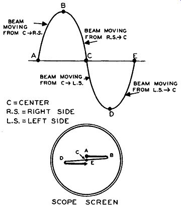
Figure 15. The Motion of the Electron Beam in the Oscilloscope When it Is
Being Driven by a Sine Voltage.
Consider the sine wave shown in Figure 15. At point A, when the applied voltage is zero, the electron beam is at the center of the screen. From A to B, the beam is deflected to the right, traveling from the center of the screen to the far right-hand edge which it reaches when the applied voltage reaches point B. At Bit pauses momentarily, then slowly starts to re trace to the left. The closer it gets to the center of the screen, the faster it travels until, at point C, it is at the center (where it was at point A) and now traveling as fast as it ever will throughout the entire sine wave cycle.
Once past the center, the beam begins to slow down (although still moving to the left). This slow down continues until point D, when the beam is as far to the left as it will go. There is a momentary pause and then the be a m starts moving back toward the center again until, at point E, it is at the center and traveling fast toward the right.
This is one complete sine wave deflection cycle.
Comparing this motion with that produced by a saw tooth wave, we see that with sine wave deflection the beam does not have a special retrace time. We could if we wished, call the left-to-right motion the tracing motion, and the right-to-left travel the retrace motion.
But in both directions the beam is sometimes traveling· fast, sometimes slow. Under the influence of a saw-tooth wave, the slower motion is toward the right and the faster motion (retrace) is toward the left.
By combining a sinusoidal sweep generator with a sinusoidally deflected scanning beam we will obtain a response pattern in which the frequency is evenly spaced. This is true because when the rate of frequency change in the generator increases the beam will be traveling faster across the oscilloscope screen. And when the frequency variation slows down, so will the rate of beam travel. The two will therefore be in step with each other and the pattern produced will neither be compressed or spread out, if the circuits are correctly aligned.
DOUBLE PATTERNS
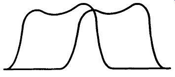
Figure 16. A Double Pattern On Figure 10 Due to Improper Phase Control Setting.
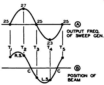
Figure 17. To Illustrate Why Double Patterns are Obtained on the Screen.
The pattern in Figure 11 is the one that should be obtained on the screen when its circuit (Figure 12) is being checked. It may frequently happen, however, that more than one pattern is obtained. See Figure 16.
Let us see why this occurs and what can be done to correct it.
The pattern in Figure 11 was obtained when the 60-cycle sine wave voltage modulating the generator was exactly in phase with the 60-cycle voltage driving the beam in the oscilloscope. Now, although the voltages for the beam deflection and the sweep generator oscillators are taken from the same source, it does not necessarily follow that these voltages are still in phase with each other by the time they actually reach the beam or the modulating circuit. The voltages are transferred from point to point by means of capacitors and resistors and such networks will alter the phase of a voltage. Consequently, it becomes evident that some form of phase control is needed at the signal generator. With this control, the phase of one of the sine-wave voltages is shifted until, at their point of application, both are in phase. Visually, the serviceman adjusts the phase control until both pat· terns on the screen blend into one.
It may be instructive to determine why a phase difference between the two driving 60-cycle voltage causes the appearance of more than one pattern; We will assume that the sine wave voltage shown in Figure 17A represents the frequency variation of the signal generator. The voltage driving the electron beam in the oscilloscope is shown in Figure 17B. The voltages, it can be seen, are out of phase by approximately 45°. Both voltages are keyed to each other to make it simpler to refer to specific points in the discussion and to the double pattern of Figure 18.
At the start, time T1, the output voltage of the signal generator is at 25 mhz. At this moment the beam is halfway between the center of the screen and the extreme right side. This is due to the positive voltage which 'is being applied to the scope deflection system at this time. If the deflection voltage were in phase with the modulating voltage, the beam would be in the center of the screen. Since curve B leads curve A by 45°, the beam is displaced to the right.
At T1 the response of the circuit to 25 mhz is such (see Figure 11) as to place the beam at the point noted in Figure 18.
From time T1 to time T2, the deflection voltage will drive the electron beam from its starting position to the extreme right side of the screen and then about halfway back toward the center. During this same interval the signal generator frequency will change from 25 to 27 mhz. Note this portion of the response curve in Figures 11 and 18. In Figure 18, a portion of the response curve is bent back on itself because the beam moves to the right-hand side of the screen and then halfway back to the center again in the time interval from T1 to T2.
From T2 to T3, the electron beam travels from its last position (.T2) to a point halfway between the center of the screen and the left-hand side of the screen. During this time the signal generator frequency will go from 27 to 25 mhz. The beam is traveling fairly fast between T2 and T3 whereas the generator is changing more slowly. As a result the visible curve on the scope screen is "stretched out" or elongated more than it is in Figure 10.
We may pause for a moment and note again that on the steep slopes between the positive and negative peaks of a s in e curve the voltage is changing quite rapidly whereas at or near the peaks it is changing slowly. In fact at the peak it stops momentarily.
This explains the stretching out of the curve.
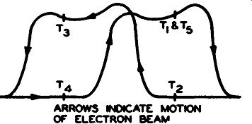
Figure 18. The Arrows Indicate the Path of the Electron Beam. T1 Through T5
are Keyed to Figure 17.
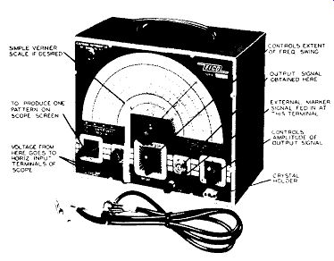
Figure 19. A Commercial Sweep Generator Which is Available in Kit Form. Courtesy
of Eico.
Between T3 and T4 the beam moves fairly slowly from its last position (T3) to the left-hand side of the screen and then back to a point halfway to the center of the screen. During the same interval the generator frequency is changing from 25 mhz to 24 mhz.
Finally, in the time interval T4 to T5 the pattern is completed.
The overall result is two similarly shaped response curves slightly displaced. By adjusting the phase control the curves can be brought together until only one is visible.
COMMERCIAL SWEEP GENERATORS
-----
* As the reader has undoubtedly guessed by now, the words sweep generator and frequency modulated or FM generator have the same meaning.
----------
There are a variety of sweep generators available to the serviceman ranging in price from $34.95 for a kit to well up in the hundreds of dollars for elaborately designed instruments capable of performing a variety of jobs.
An example of what is available in the kit classification is the instrument shown in Figure 19. It is designed to cover, roughly, a range of frequencies from 500 khz (.5 mhz) to 227 mhz. On the main tuning dial the bottom scale is a reference scale marked from 10 to 100 linearly. (This might to some extent be employed as a vernier scale although it would obviously be a very rough vernier scale. As we shall see in a later section, precise calibration of the scale of a s wee p generator is not as important as the precise calibration of the dial of an AM generator.) The next three scales marked "Center Sweep Frequencies" and calibrated from 0-60, 0-120, and 168-227 are the center frequencies about which the sweeping takes place. For example, if the main dial pointer is set at 100 megacycles and the " Sweep width'' control is set at a maximum sweep width of 30 megacycles, the output frequency will sweep back and forth from 85 to 115 megacycles.
The uppermost scale is for an internal oscillator operating from 54 to 114 mhz. In this particular instrument this scale is used in calibrating the instrument and also is useful as a Source of standard RF signals in the above range.
The reader will notice that all output ranges are available without bandswitching. How this can be accomplished will become evident when the description of the circuit is given later.
The various controls found on this instrument are as follows:
"SWEEPWIDTH" CONTROL: This control varies the amount of sweep width about the center frequency indicated by the main tuning dial pointer. It is calibrated 1 in early from 0 to 30 megacycles and intermediate points give an approximate indication of the actual amount of sweep.
"RF ATTENUATOR:" This control determines the strength of the RF signals delivered to the RF output connector.
"RF OUTPUT" CONNECTOR: The coaxial cable supplied with the instrument is attached to this connector and the output fed to the FM or TV receiver being aligned.
"60 CYCLE" OUTPUT TIP JACKS: These tip jacks are used to supply 60-cycle voltages to the horizontal deflection amplifiers of the oscilloscope used. Connect two test leads from these tip jacks to the horizontal binding posts on the oscilloscope or use a shielded cable.
"PHASING CONTROL:" This control varies the phase of the 60-cycle AC supplied through the tip jacks. Always adjust this control to obtain a single trace on the oscilloscope screen.
When turned to the extreme counter-clockwise position, the sweep generator is turned off.
"CRYSTAL" SOCKET: External crystals are inserted in this socket to obtain marker points on the trace being observed for calibration purposes and for use as a crystal controlled RF signal for external applications. When a crystal is inserted, it is connected in a oscillator circuit which oscillates at the crystal frequency, also producing harmonics such as the 2nd, 3rd, 4th, 5th, 6th, etc. For example, a 5 mhz crystal will produce harmonics at 10 mhz, 15 mhz, 20 mhz, 25 mhz, 30 mhz, etc.
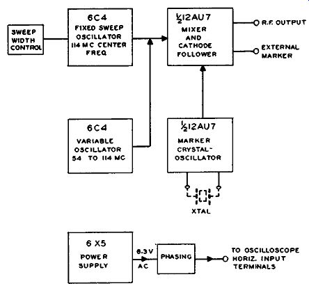
Figure 20. A Block Diagram of the Sweep Generator Shown in Figure 19.
"CRYSTAL AMPLITUDE" CONTROL:
This control varies the output of the crystal marker oscillator. It should be adjusted for minimum observable output; so that it has the least effect on the pattern observed. The output of the crystal marker oscillator is connected so that its output together with that of the sweep generator is varied simultaneously with the "RF Attenuator" control.
"EXT. MARKER" BINDING POSTS: These binding posts allow injection of an external marker, such as a standard AM signal generator. The ground lead of the external AM signal generator is connected to the binding post marked" GND" while the high side is connected to that marked "Ext. Marker" . The output of the external marker can be varied simultaneously with the sweep generator output using the "RF Attenuator".
CIRCUIT DESCRIPTION
A block diagram of the system used in the EICO Model 360 sweep signal generator is shown in Figure 20. An oscillator with a fixed center frequency of 114 megacycles is frequency modulated to a maximum sweep-width of 30 megacycles, sweeping this fixed oscillator back and forth from 99 to 129 megacycles.
The amount of frequency modulation is controlled by the "Sweep-width" control setting.
From the block diagram it is seen that the out put of the fixed sweep oscillator is heterodyned or mixed with that of a variable oscillator. The latter variable oscillator is a standard Hartley oscillator having a frequency range of 54 to 114 mhz which is controlled by the main tuning dial setting. The resultant beats or heterodynes between these two oscillators (one fixed and frequency modulated and the other variable) profile the frequency ranges of the instrument. For example, the difference frequencies between the 114 mhz fixed swept oscillator and the 54-114 mhz variable oscillator provide the frequency range of 60 to 0 mhz. The sum frequencies of the two oscillators provide the range of 168 to 228 mhz. The second harmonic of the difference frequencies gives the range 120 to 0 mhz.
The output of these two oscillators is " mixed" in the mix e r tube which also serves as a cathode follower output tube. This tube is 1/2 of a 12AU7 dual triode, the other half being used in a Pierce crystal oscillator circuit. A schematic diagram of the instrument is shown in Figure 21.
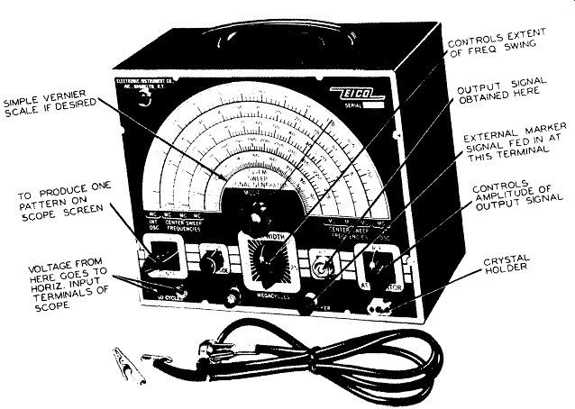
Fig. 19
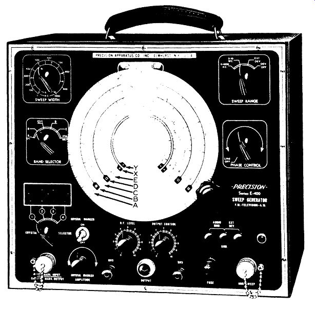
Figure 22. A Precision Model E400 Sweep Generator. (Courtesy of Precision
Apparatus Company, Inc.)
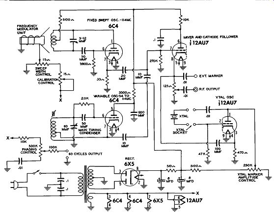
Figure 21. A Schematic Diagram of the Eico Sweep Generator.
PRODUCING FREQUENCY MODULATION OF THE FIXED SWEPT OSCILLATOR.
The fixed swept oscillator at a center frequency of 114 mhz is frequency modulated by mechanical means. The oscillator coil consists of a specially designed, flat open wound spiral coil embossed on a bakelite base plate. A flat metal membrane is placed parallel and very close to this coil, and is mounted on the diaphragm of a speaker. When the diaphragm is vibrated, the metal membrane vibrates varying the inductances of the oscillator coil which is very close to it. The oscillator frequency is thus varied. To obtain different sweep widths, a rheostat varies the amount of voltage applied to the speaker voice coil. The greater the voltage, the greater the diaphragm vibration, and the greater the frequency variation.
A WIRED SWEEP GENERATOR
A sweep generator which is more elaborate than the previous instrument is the unit shown in Figure 22. Continuous frequency coverage from 2 megacycles to 240 megacycles is achieved in five bands without any skip. Furthermore, the harmonics are strong enough so that it is possible to go as high as 480 megacycles and appropriate scales are provided for these higher frequencies.
This unit is manufactured by the same firm that produced the AM generator shown in Figure 9, Section 2. It, too, contains a vernier scale and vernier plate. Of the 160 divisions contained on the vernier scale, only 150 of them are useful so far as the frequency scales are concerned. This 150, however, should be multiplied by 10 because of the vernier plate. Hence, a direct reading to one part in 1500 is possible and this provides greater accuracy than would be needed in a sweep generator for any application.
Before we examine the various front panel controls, it may be instructive to examine briefly the circuit of this generator. See Figure 23. With sweep generators, even more than AM signal generators, it is to the advantage of the serviceman to know as much as possible about the operation of the instrument. The sweep generator is a fairly complex piece of equipment, subject to misuse or misapplication. The serviceman who comes in daily contact with sweep generators may not appreciate it, but actually, to know how to apply such an instrument properly and to its fullest extent requires a greater amount of technical know-how than it does to operate an AM generator.

Figure 22. A Precision Model E400 Sweep Generator. Courtesy of Precision Apparatus
Co., Inc.
OSCILLATOR "A". This is a variable oscillator covering a fundamental range of 71 to 120 mhz. At every point within this frequency range, the oscillator is frequency modulated by the same electro-mechanical method as the previous generator.
The oscillator frequency is thereby varied above and below the oscillator mean frequency at a 60-cycle repetition rate.
(In the previous instrument, the variable oscillator was not modulated at all. Here, it is.)
OSCILLATORS "B" and "C" are fixed frequency oscillators calibrated at 75.0 mhz and 37.5 mhz respectively. In operation only one of these oscillators is in u s e at any one time. The output of oscillator "A" and either oscillator "B" or "C" are simultaneously injected into a high frequency RF mixer stage labeled '' D" . This stage mixes the signals of oscillator "A" with those of" B" or "C" and delivers the carriers, sum and difference frequencies to the '' RF Amplifier -Marker Injection' ' stage (labeled " E" ) . A crystal oscillator (labeled " F") provides for the simultaneous insertion of any one of four crystals for applications requiring use of crystal-accuracy marker and calibrating pips. The use of a 4-crystal holder eliminates the inconvenience of frequent insertion and removal of crystals. Each of the 4-crystal positions is quickly selected by a rotary switch and the crystal marker amplitude may be controlled separately.
In addition, variable frequency marker input terminals provide a direct means for use of any standard, suitable AM signal generator as a marker pip-generator.
FUNCTION AND DESCRIPTION OF FRONT PANEL CONTROLS AND SWITCHES
Main Tuning Dial and Band Selector Switch
(a) The markings "A(X)," "B," "C(Y)," " D," and " E" on t h e " Band Se lee tor" switch refer to the corresponding bands on the main tuning dial.
(b) The marking "A(X)," "C(Y)," indicate that bands "A" and "X" are in operation when the "Band Selector" is set to "A(X)" and that bands "C" and "Y" are in operation when the "Band Selector" is set to "C (Y)" . (c) When the "Band Selector" switch is rotated to the position marked "Xtal only" all oscillators with the exception of the internal Crystal Marker oscillator are disabled, permitting application of just the pure Crystal Marker oscillator output as a simple crystal oscillator for external use with no interference from the remainder of the generator's oscillators.
"SWEEP WIDTH" CONTROL: Rotation of the '' Sweep Width'' control varies the degree to which the variable oscillator (Osc. "A") is deviated from its mean frequency. For example: if the "Sweep Width" control is set to 200 khz and if the main tuning dial is set to 10. 7 megacycles, the RF output from the sweep generator will be varying from approximately 10,800 khz (10.8 mhz) to approximately 10,600 khz (10.6 mhz) at a 60-cycle rate. Therefore, the calibration on the "Sweep Width" dial indicates total sweep width, not deviation to each side of the mean frequency. The deviation is only 1/2 of the total sweep.
The calibrations of the "Sweep Width" control are NOT intended for use as accurate indications of sweep width at every setting of the main dial. They a r e intended for u s e as a convenient guide to the approximate setting required to bring the full response pattern into view on the scope screen. This is true of all sweep generators.
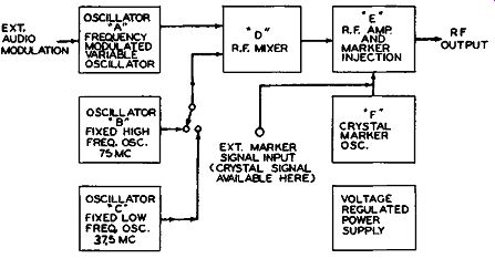
Figure 23. A Simplified Block Diagram of the Sweep Generator Shown in Figure
22.
" SWEEP RANGE" SWITCH: This switch sets the range for which the "Sweep Width" control is calibrated, (0-1000 khz or 0-15 mhz). The third position (marked " Ext. Dev." ) frees the modulator from its internal 60 cycles excitation and allows the operator to excite the modulator from an external AC source through use of the panel pin jacks marked " Ext. Dev." The fourth position (marked "Dev. Off") disables the modulator from both internal and external deviation sources. Under this fourth condition, all frequencies indicated on the main tuning dial are un-modulated RF signals. Should a source of audio frequency voltage then be applied to the ''Audio Mod.'' pin jacks on the front panel, the output of the generator becomes an amplitude modulated (or AM) signal generator. This is a useful feature of this generator and is not always available on other instruments.
"PHASE CONTROL:" Due to the fact that full sinusoidal voltages are simultaneously applied to the electro-mechanical modulator and the "Hor. Sweep" terminals of the oscillograph, two traces of the tuned circuit response curve will normally appear on the oscillograph. Without corrective network, one of the traces will usually be found out of phase with the other trace, resulting in both traces appearing on the oscilloscope, adjacent to each other. The "Phase Control" operates a capacity phase-shift network which permits both traces to be superimposed on the oscillograph.
The inherent characteristics of the modulator unit are such as may sometimes prevent exact super imposition of the two traces (by manipulation of the "Phasing Control"). As a result, it may be found (w he n w id e sweep width is employed) that similar portions of the two traces may lie closely adjacent to each other instead of being exactly superimposed.
This has absolutely no effect upon the overall operation and can be disregarded by the operator.
"RF LEVEL" and "OUTPUT CONTROL:" The control labeled "RF Level" adjusts or controls the magnitude of RF which is fed or transmitted to the "Output Control." With the "Output Control" set to maximum, the "RF Level" control should be set at a point which will result in the maximum out put required for the particular application. From that point on, the "Output Control" is used to attenuate the signal from the sweep generator.
" CRYSTAL MARKER:" (Selector, Attenuator, Panel Connector and Switch).
(a) "Crystal Selector" Switch. When one to four appropriate crystals are inserted into the multiple crystal socket this switch will select any one of the 4 crystals and electrically insert it into the internal oscillator circuit.
(b) Crystal Marker "On-Off" Toggle Switch. This switch permits the internal crystal marker oscillator to be turned On or Off. When the internal crystal marker is not required, this toggle switch should always be thrown to the "Off" position.
(c) "Crystal Marker Amplitude" Control. The "Crystal Marker Amplitude" control is an attenuator for the internal crystal marker oscillator. In use, the amplitude or height of the marker "pip" will increase as the control is turned clockwise. This control should be advanced only as far as required to just make the " pip" visible. If the control is advanced to obtain an excessively strong "pip" , the overall response curve may be distorted by the strong marker signal.
(d) "Ext. Mark. Input - Crystal Mark. Output" Connector. This connector in the lower left-hand corner of the panel, permits the operator to obtain externally the output of the crystal marker oscillator only, for a variety of purposes. For this function, the " Band Selector" Switch is rotated to the" Xtal Only" position.
At the s a mhz terminal another generator can inject an external marker signal into this instrument.
This marker signal will combine with the swept signal, traveling with this latter signal to the circuit under test.
"HOR. SWEEP" CONNECTOR. This connector supplies a horizontal sweep actuating voltage to the horizontal input terminals of the oscilloscope being used.
"EXT. DEV." PIN JACKS (External Deviation). With the " Sweep Range" selector switch rotated to the "Ext. Dev." position, an external source of AC voltage at a frequency between 25 to approximately 200 hz. may be applied to the "Ext. Dev." pin jacks, thereby externally exciting the modulator. Care must be taken when applying AC voltage to the" Ext. Dev." pin jacks. Should excessive voltage be applied, the modulator driving coil may be overloaded and damaged. Apply only enough voltage as will yield sufficient sweep width to bring the entire response curve of the tuned circuit under test into view on the oscillograph screen. (Approx. 1.5 volts maximum). When an external source of sweep potential is employed, the approximate deviation calibrations of the "Sweep Width" control are no longer applicable.
Also, the '' Hor. Sweep'' connector still puts out a 60-cycle sine wave driving voltage which would not be suitable with any external modulating voltage except one whose frequency was also 60 cycles.
"OUTPUT" CONNECTOR. A coaxial cable connects to the " Output" connector on the instrument panel.
BINDING POSTS ON PANEL.
These binding posts are provided for additional grounding connections to be made by the operator. One grounding strap should be connected from one binding post on the panel to the receiver under test. If found necessary, another ground connection may be made by the operator from the other binding post to another point on the receiver or to the oscilloscope being used.
INITIAL SET-UP OF INSTRUMENT.
Before we leave this instrument, it may be advantageous to note how it would be set up initially--in preparation for an alignment. When a generator is being used in the shop, perhaps by several people, it may come to the serviceman who is now going to use it with the controls set in almost any fashion, depending how the previous man employed it. To the inexperienced serviceman, the resetting of the controls is perhaps as big a job as the actual performance of the alignment procedure itself. Toward that end, the following preliminary set-up procedure will be of interest.
(a) "PHASE CONTROL" is set at approximately mid position.
(b) " BAND SELECTOR" switch is set to the proper frequency band.
(c) The m a in tuning dial is rotated to the mid frequency of the range to be covered.
(d) " SWEEP RANGE" switch is set to the proper range (0-1000 khz for FM; and 0-15 mhz to TV).
(e) The position of the "SWEEP WIDTH" knob will depend on the passband of the circuit to be swept over. Generally the generator sweep should have a value about 50 percent greater than the maximum band pass of the circuit under test. For a 4.0 mhz TV system this would mean setting the "Sweep Width" control to 6 mhz.
(f) The "RF LEVEL" and "OUTPUT CON TROL" knobs should be advanced to full rotation.
This will insure maximum output at the start.
(g) Initially there would probably be no need for a crystal marker and so the "Crystal Marker" switch would be thrown to the "Off" position. With the crystal oscillator thus made inoperative, the position of the "Crystal Selector" switch would be of no consequence.
The instrument, with the power on, would now be ready for connection to the receiver with which it is to be used. Just what this next phase of the operation is, will be covered in detail in a later section. At the moment we a r e primarily concerned with becoming familiar with the instrument and its capabilities and controls.
SWEEP GENERATORS WITH INTERNAL VARIABLE MARKERS
The s wee p generators which have been described to this point have been designed for use with an external variable marker generator for the identification of different frequency points along the response curve. In the generator shown in Figure 24, such a marker oscillator is actually made part of the sweep instrument itself. The ranges covered by the marker unit are 19 to 31 mhz and 30 to 48 mhz. A separate dial is employed for the marker generator so that any of its frequencies may be chosen independently of the sweep frequency generator.
The output of the marker generator is combined with the sweeping signal and then both may be obtained from the terminal marked "Output." The amplitude of the marker pip can be controlled by the "Marker Injection" knob.
A crystal may be plugged into the external holder to permit accurate adjustment of the receiver oscillator. Extremely accurate pips may also be generated for fixed markers on the response curve when proper crystals are used. Crystals are avail able from the factory for any frequency between 10 mhz and 215 mhz.
Finally, an external signal generator may be connected between the "External Marker" pin jack and " GND" to pr o v id e an additional marker frequency if it is desired. Since this binding post is internally connected to the marker oscillator and crystal oscillator circuits, it is possible to obtain from this pin jack signals directly from either of these oscillators.
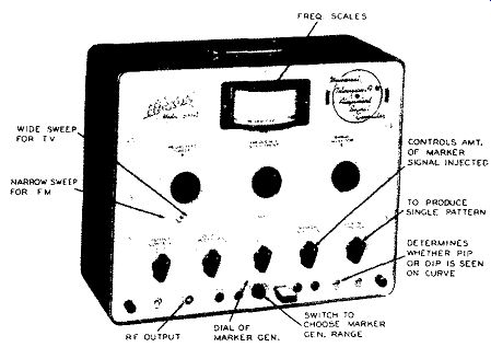
Figure 24. A Sweep Generator Possessing its Own Marker Generator. Courtesy
of Hickok Electrical Instrument Co.
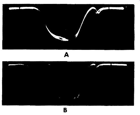
Figure 25. A Comparison Between the Appearance of a Conventional Pip Produced
by the Beat Method (A), and a Pip ( or Dip, Actually) Produced by the Absorption
Method (B).
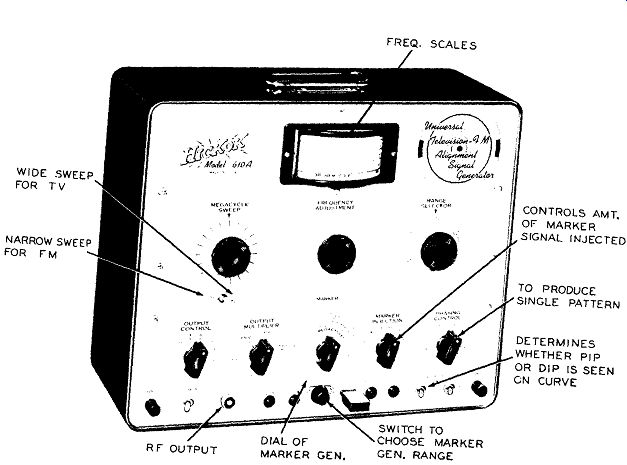
Figure 24. A Sweep Generator Possessing its Own Marker Generator. (Model 610-A,
Courtesy Hickok Electrical Instrument Co.) Figure 26. A Sweep and Marker Generator
with Blanking and Reverse Sweep Features. (Model TVG2, Courtesy of Jackson
Electrical Instrument Co.)
Of particular interest is the use of the marker generator signal to align the various trap circuits and peaking coils in the video IF system of a television receiver. 400-cycle modulation of this. marker generator output c an be achieved by flipping the " Int. Marker" switch (located in the lower right-hand corner of the panel) to the "Mod." position. If an unmodulated signal is desired, the switch is moved to the "CW" position. When the instrument is being used to sweep out a response curve, the switch is normally in the "CW" position.
Next to the "CW" -"Mod." switch is another switch containing the words "ABS" and "Osc." In the "Osc." position, the marker generator signal produces a pip on the response curve, as shown in Figure 25A. However, in the "ABS" position, the pip is changed to a dip in the curve. See Figure 25B. The use of marker signals in receiver circuit alignment is actually a consequence or by-produce, as it were, of using sweep frequency generators to perform circuit adjustment. When you obtain the response curve of any system on an oscilloscope screen, you must have some way of determining the various frequency points on that curve in order to determine, first, if the curve extends over the proper range and second, if specific frequencies are located where they should be. It is the function of the marker generator to provide this information and it does so in the following manner. The signal from the marker generator is combined with the signal from the sweep generator and both are then passed through the system to be aligned.* At the output of this circuit both voltages are applied to a detector (usually the video second detector of the receiver) where the marker frequency beats with the sweep frequency signal to produce a series of sum and difference frequencies.
As a concrete illustration, suppose the sweep generator is sweeping from 22 to 28 mhz and the marker generator is at 25 mhz. Then when these signals reach the video second detector after having passed through the video IF system, they will beat together. The 25 mhz marker will beat with the sweep generator's 25 mhz to produce a difference frequency of zero cycles (OC). As the sweep generator moves away from 25 mc, say to 25.001 mc, then the best difference frequency produced will be .001 mhz or 1,000 cycles.
At 25.002 mhz, the best difference frequency will be 2,000 cycles, etc. In other words, the marker signal will beat with the sweep signal at every frequency within the 22 to 28 mhz sweep range. The sum frequencies produced will extend from 47 mhz to 52 mhz and since frequencies this high will never pass through the vertical deflection circuits of the oscilloscope, they can be disregarded. The difference frequencies produced by this beating action will extend from 0 (when both signals are at 25 mhz) to 3 mhz when the sweep generator is either at 22 mhz (25 mhz -22 mhz) or at 28 mhz (28 mc-25 mhz).
Now, since the vertical deflection amplifiers of most oscilloscopes seldom have a flat response be yond 500,000 cycles, all the difference frequencies produced above this value (i.e., 1/2 mhz) will either be attenuated or eliminated altogether. In addition , if we place a small by-pass capacitor (500 mmf. or so) across the input terminals of the oscilloscope, all but the very low beat frequencies will be shunted away from the oscilloscope circuits and will not appear on the screen. The result, as shown in Figure 25A, is a fairly well defined pip on the screen.
Note, then, that this pip is produced by the very low beat frequencies which occur when the sweep frequency is close to the marker frequency. In this discussion this would be at 25 mhz. Beat frequencies are produced at all other sweep frequencies but be cause of the factors mentioned above, do not appear on the screen.
* Additional information on producing marker pips is also found in a later section on Special Test Instruments.
The scanning beam in the oscilloscope is moving across the screen in step with the changing frequencies coming out of the sweep generator to trace out the response curve. When we introduce the marker signal into the circuit, the pip it produces will appear at that point on the curve where the sweep signal frequency is the same as the marker signal frequency. If we change the marker frequency, the beat between it and the sweep signal occurs at some other point in the sweeping range and, on the response curve, the pip moves to a different position. In this way we can move the pip to whatever section of the curve we wish and note from the marker dial just what the frequency of the curve is at that point.
Most marker pips are produced by the beating method. Another method, available in the generator of Figure 24, is an absorption type of marker where the voltage in the sweep signal having the same frequency as the absorption circuit is " sucked out" or absorbed by the marker circuit. The indiction that this type of marker provides is shown in Figure 25B and is seen to be actually a dip or notch in the response curve.
BLANKING CONTROLS
Figure 26. A Sweep and Marker Generator With Blanking and Reverse Sweep Features. Courtesy of Jackson Electrical Instrument Company.
Figure 27. The Appearance of a Response Curve and its Zero Reference Retrace Line When Blanking Is Employed in Sweep Generator.
Figure 28. The "S" Response Curve of an FM Detector With Zero Reference Line Produced by Blanking Circuit in the Sweep Generator.
The sweep generator shown in Figure 26 contains an internal marker oscillator, a sweep generator, and the usual controls that go with these two generators. Of interest are the additional features contained in this instrument since they may, in one for m or another, appear in other sweep generators that the serviceman is likely to encounter. These features include a "Blanking" or "Double Pattern" switch, a method of injecting video modulation, a beat detector jack, and a method of reversing the sweep.
The " Blanking" or "Double Pattern" switch, located in the lower right -hand corner of the instrument panel determines, by its position, whether the normal double pattern will be seen on the oscilloscope screen or instead a single pattern with a base line.
The blanking circuit when turned on, injects a negative pulse into the FM oscillator circuit in such a manner that oscillation is stopped during the return trace of the oscilloscope, thereby producing a base line and a single trace response curve on the oscilloscope screen. Thus, as the electron beam sweeps forward from left to right, the response curve of the circuit under test is traced out. On the return trip, the beam would ordinarily trace back over the same curve. This second tracing is not actually necessary since it provides the same information as the forward trace. Furthermore, there is generally sufficient un balance existing in the circuit so that the second trace does not coincide at all points with the first trace, resulting in two curves. This second trace can be removed by stopping the oscillations of the sweep generator during this period and that is what happens when the " Blanking" switch is flipped on the generator of Figure 26. Within the scope, however, the beam is not similarly blanked out and so it produces a zero voltage or reference line because during this period it is receiving nothing from the circuit under test. See Figure 27. (The circuit, by the same token, is not putting out any voltage because it is receiving nothing from the sweep generator.) The presence of the base line aids the technician to better orient the various values of the response curve and there by tends to simplify and hasten the servicing and alignment process. The zero base line proves to be especially valuable for FM discriminator alignment since in this instance the linear portion of the S-response curve should extend for equal distances above and below this level. See Figure 28.
VIDEO MODULATION
A connector is provided as a means of inserting a video signal from a normally operating television receiver into the generator. This signal modulates the marker oscillator to " rebroadcast" this video signal on any desired channel or frequency. It may also be used to insert an audio signal, either sine or square wave, for line a r it y adjustment. (The marker generator, in three ranges, covers the frequencies of 4 mhz to 216 mhz.) The manner in which the video modulation feature can be employed will be seen from the following:
1. Video modulating the Marker Generator.
(a) Turn the instrument on and set the "Marker" selector to "Variable" position.
(b) Set the "Range" switch (underneath the marker generator) to Band "C" and the dial to the picture carrier frequency of the channel to be checked.
(c) Connect the "RF Output" cable of the generator to the antenna terminals of the television receiver to be checked.
(d) Tune in a picture from a television station on a normally operating television set. (This is another set, not the one to be tested.)
(e) Using a shielded lead, feed the video signal from the good TV set picture grid into this generator through the '' Video Mod." connector. A 0.1 mfd. capacitor should be placed in series to isolate the DC voltage from the set.
(f) If the picture appears reversed (negative picture) on the screen of the set under test, adjust the contrast control on the set feeding the video signal. If this does not correct the condition, then the video signal should be taken from s o m e other point in the TV set where its polarity is opposite to what it is at the picture tube. This point is generally at the grid of the last video amplifier. Note, then that the detected signal from the good set' is used, in conjunction with the signal generator, to provide a test signal, for the set to be checked . Such a procedure might be feasible when only one station is on the air yet you wish to check receivers on other channels. The video signal you derive from one set could be used to modulate the signal generator on any frequency. An arrangement of this type is also useful when no stations are on the air but you have a source of video signal available in the shop.
(A video signal generator suitable for this purpose is described in a later section.) With this equipment you can generate your own video RF signals.
2. Modulating to produce Bar Patterns. Vertical and horizontal bars on the picture tube raster offer a method of checking horizontal and vertical linearity adjustments of a television receiver. By using an audio oscillator capable of generating multiples of the vertical (60 cycles) or horizontal sweep frequency (15.75 khz), it is possible to produce vertical or horizontal bars with this instrument.
(a) Obtain a signal from the variable marker oscillator by the procedure described above. (Steps la, b, and c.)
(b) Select a picture carrier frequency and feed the RF output into the antenna terminals, or select the picture intermediate frequency and feed the RF output to the grid of the first video IF stage.
(c) Feed the output of the audio oscillator into the " Video Mod." connector.
(d) To produce horizontal bars to check vertical linearity, s et the audio frequency oscillator to a multiple of the 60-cycle receiver vertical sweep frequency. As an example, if the audio frequency is 600 cycles, 10 horizontal bars should appear. The top or the bottom bar may be decreased in width, due to the retrace time of the receiver vertical sweep oscillator.
(e) To produce vertical bars to check the horizontal linearity, set the audio oscillator (or AM generator) to some multiple of the 15.75 khz horizontal sweep oscillator frequency. If the applied frequency is 157.5 khz, 10 vertical bars will appear. If the frequency is 78.75 khz, 5 vertical bars should appear. Equal spacing between bars indicate good linearity.
Note: For satisfactory modulation, either video or bar pattern, between 5 and 10 volts will be necessary at the " Video Mod." connector.
BEAT DETECTOR
A terminal is provided as a means of connecting headphones to hear, or connecting an oscilloscope to observe, the zero beat between the crystal oscillator and the variable marker oscillator for calibration.
The manner in which this calibration is accomplished is as follows: (a) Plug in the desired calibrating crystal in the panel holder provided for it. As an example: A 12.5 mhz crystal to check the 25 mhz point on Band " B" of the variable or marker oscillator. ( Crystal oscillators produce strong harmonics and it is feasible to use lower frequency crystals when the desired frequency is quite high. Lower frequency crystals are also sturdier and less expensive.) (b) Turn the " Marker" selector switch to the "Calibrate" position and allow the instrument to warm up for at least 10 minutes.
(c) Set the marker frequency dial to the 25 mhz reading.
(d) Connect headphones to the" Beat Detector" jack. Swing the marker frequency dial back and forth until a beat note is heard.
(e) At the zero beat point, note the dial reading.
If the scale is off, you can do one of two things. First, either bring the frequency of the generator back into line by making such adjustments as are recommended by the manufacturer or second, drawing up a calibration chart in which you list on one side the frequency markings as they are on the dial and on the opposite side, the correct value of each of these markings. In following this latter procedure, only the major scale markings need be checked.
USING AN EXTERNAL MARKER SIGNAL
This instrument (Figure 26) is capable of developing its own marker signal. However, if it is desirable (as it frequently is) to use 2 marker pips on a given response curve, this may be accomplished by connecting an accurate RF s i g n a l generator to the "External Marker" connector and setting it to pro duce the desired marker frequency. The output control of the auxiliary oscillator should be adjusted to give approximately the same size " pip" as the one produced by the generator of Figure 26.
Incidentally, it will undoubtedly occur to many readers that the calibration of other AM generators may be checked against the crystal oscillator in this instrument. Simply connect the external generator to the "External Marker" connector. Then plug in the appropriate crystal in the crystal holder. and turn the "Marker" selector switch to the" Crystal" position.
connect headphones to the "Beat Detector" jack.
Then swing the dial of the external generator back and forth slightly until a beat note is heard.
SWEEP PHASE REVERSAL
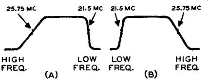
Figure 29. (A) A Video IF Response Curve That Maybe Obtained on the Scope
Screen. Note That the High IF Frequencies Are at the Left and Low IF Values
at the Right. (B) By Flipping the Phase Reversal on the Jackson Generator,
the Curve in (A) Is Reversed to the Form Shown in (B).
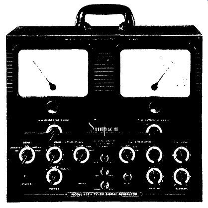
Figure 30. A Crystal-controlled AM, FM, and TV Sweep Generator. Courtesy of
Simpson Electric Co.
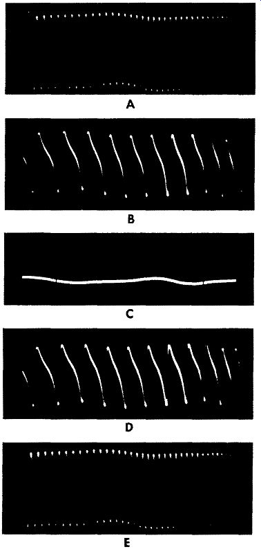
Figure 31. A Sequence of Patterns Passing Through Zero Beat. Zero Beat is
Obtained at " C" , " A" , "B", "D" and "E" Are
Above or Below Zero Beat.
The "sweep" control has "Off-On-Reverse" positions. In the "Off" position, the 60-cycle driving voltage is removed from the FM oscillator and the output from the sweep section is unmodulated RF. In the "On" position the driving or sweeping voltage is applied to the FM oscillator and the sweep section is delivering an FM signal. This, when fed to a tele vision receiver, would produce a response pattern.
Now, it can happen, because of the manner in which the test equipment is designed, that in the response pattern obtained, the high frequency end of the curve is at the left and the low frequency end is at the right.
See Figure 29A. All this means is that the oscilloscope tracing beam is at the left-hand side of the screen when the sweep generator is sweeping out the high frequency end of the response curve. It does not affect the response curve or its circuit in any way.
However, the reversed pattern can sometimes confuse the technician since many textbooks and instruction manuals show response curves with the low frequency section at the left and the high frequency section at the right, as in Figure 29B. To reverse the curve so that it can be compared with the standard patterns, this generator contains a reverse position on its "Sweep" selector switch and by turning to this position, the direction of sweep is reversed.
A SECOND TYPE AM - FM - TV GENERATOR
Combination AM, FM and TV generators are gradually becoming more common as the scope of the servicing field expands. The generator in Figure 24 could be considered as representing an initial step toward achieving this combination by including a marker generator (of limited range) with its sweep generator. The next instrument (Figure 26) took a longer step forward in this direction not only by extending the range of its marker generator, but by adding such extras as a beat detector jack, a phase reversal switch, and making provision for audio and video modulation. Still another generator along some what the same lines is the unit shown in Figure 30. Physically this instrument is divided into two sections: A right-hand section and a left-hand section. Grouped on the left is a three-range RF generator, a crystal calibrator, and a 400-cycle audio oscillator.
The type of signal desired is selected by a "Signal" selector switch (left). When this switch is in the "Off" position, the section is inoperative. In the "Unmod. RF" position, an unmodulated RF signal is available at the
Output cable and controlled through the two "Signal Attenuator" controls. In the " Cal." position, a 5 mhz crystal oscillator or one of its harmonics is mixed with the RF signal or one of its harmonics to produce a "beat" pattern which can be observed on an oscilloscope screen and thus provide an accurate means of adjusting the RF signal to an exact frequency.
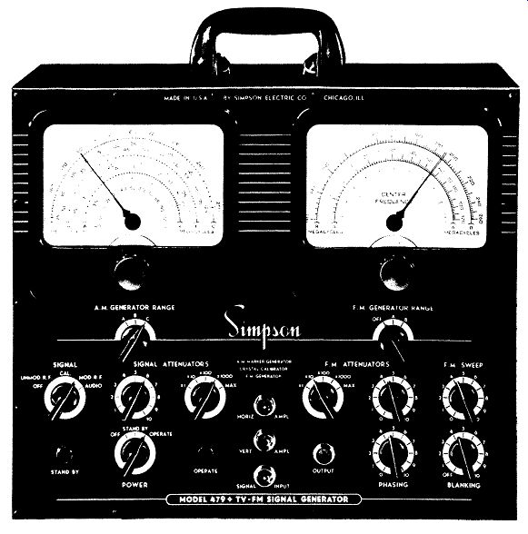
Figure 30. A Crystal Controlled AM, FM and TV Sweep Generator. (Model 479,
Courtesy of Simpson Electrical Co.)
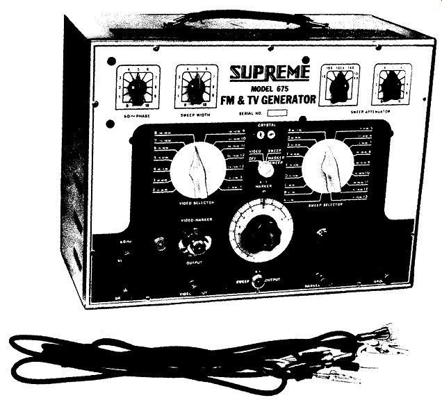
Figure 32. An FM-TV Generator in Which the Sweep Frequencies Are obtained
at Certain Fixed Positions of a Selector Switch. (Model 675, Supreme Instrument
Co.)
To see this beat pattern, the "Output" cable would be connected to the vertical input terminals of an oscilloscope. As the AM signal generator dial is turned .slowly through zero beat, the sequence of patterns shown in Figure 31 will be observed. The one which is obtained at zero beat is indicated. To determine the precise point where zero beat occurs, it is necessary to turn the generator dial as slowly as possible. Even so, at higher frequencies, it may be quite difficult to determine exactly when zero beat is reached because even a hair's turn of the dial will change the generator's frequency enough to cause it to pass through zero be at and be several hundreds of cycles away from it. In such situations it is best to go back and forth over the zero beat point until you have narrowed it down as closely as you can.
When the "Signal" control is in the "Mod. RF" position, a 400-cycle modulated RF signal is available at the output cable and controlled by the two "Signal Attenuator" controls.
In the "Audio" position, a 400-cycle audio signal is available at the output cable and controlled through the "Signal Attenuators." The "AM Generator Range" switch (upper left) together with the tuning dial selects the desired RF signal.
Band" A" Fundamental 3.2-8 mhz second harmonic 6.4-16 mhz.
Band ti B" Fundamental 15-38 mhz second harmonic 30-76 mhz.
Band "C" Fundamental 75-125 mhz second harmonic 150-250 mhz.
The " Power" switch (lower left) controls the power input to the unit. In the "Off" position the entire instrument is turned off. In the "Stand By" position all tube heaters are on but no plate voltage is applied. In the "Operate" position the plate supply is turned on. The green light (left) is on in the t1 Stand By" position and the red light (right) indicates the "Operate" position.
The right-hand section of this instrument contains a frequency modulated signal generator, a 140 mhz fixed frequency oscillator, mixer, phasing and blanking circuits.
The fundamental range of the FM generator is 140 to 260 mhz and is available at the "Output" terminal when the" FM Generator Range" switch (upper right) is in position "B". In position "A" the 140 mhz fixed oscillator is in operation and is mixed with the FM generator to produce difference frequencies from 2-120 mhz. In the "Off" position, both oscillators are inoperative.
The " FM Sweep" control (right) regulates the amount of frequency sweep from zero to over 15 megacycles. (The numbers on this dial are for reference only.) The " FM Attenuator" controls the output from the FM section.
The " Phasing" control adjusts the horizontal sweep of the oscilloscope to coincide with the frequency sweep of the oscillator in order to super-impose the return trace on the forward trace.
The " Blanking" control injects a negative pulse into the FM oscillator circuit in such a manner that oscillation is stopped during the return trace of the oscilloscope thus producing a base line and a single trace response curve on the cathode-ray tube.
The output attenuator is a step attenuator through which all signals must pass into the" Output" jack directly below it.
Figure 32. An FM-TV Generator in Which the Sweep Frequencies are Obtained
at Certain Fixed Positions of a Selector Switch. Courtesy of Supreme Instrument
Co.
Four cables are supplied for making connections between the generator, the receiver and the oscilloscope.
After the sweep signal has passed through the receiver and it has been demodulated by the video second detector, it is returned to the generator by means of a coaxial cable to the "Signal Input" terminal where it passes through to the "Vert. Ampl." cable and from here to the vertical amplifier of an oscilloscope. This arrangement was designed to simplify the alignment operation by internal switching of the oscilloscope input. (Note: The receiver output c a n be f e d directly to the oscilloscope, if desired, The arrangement suggested her e is only for convenience.) The '' Horiz. Ampl.'' cable connects to the horizontal amplifier of the oscilloscope to provide a synchronized 60-cycle sine wave sweep with variable phasing.
--------------------
CHANNEL selector--Switch to the desired TV channel or to intermediate-frequency range. When this selector is at positions "12" through "13", the rf-output voltage appears at the RF OUT terminal. When the selector is at "IF" position, the output if and video frequencies are determined by the IF /VIDEO control and are obtained at the IF /VF OUT terminal.
SWEEP WIDTH control--Has two functions; turns the power on between positions "OFF" and "1", and adjusts the sweep width of the output voltage.
IF/VF ATTEN control--Permits continuous adjustment of the amplitude of the if/vf output (at IF /VF OUT terminal) when the CHANNEL selector is at "IF" position.
IF /VF OUT terminal--The if/vf output voltage appears at this terminal when the CHANNEL selector is at "IF" position.
IF /VIDEO control-Tunes the variable-frequency oscillator to produce the desired if and video frequencies at the IF /VF OUT terminal with the CHANNEL se lector at "IF" position.
SCOPE terminal--A sinusoidal voltage of line frequency, which can he applied to the horizontal-input terminals of an oscilloscope, appears across this terminal and the GROUND terminal. The phase relationship of this sweep voltage and the output of the WR-59B can he adjusted by means of the PHASE control to produce a single pattern on the oscilloscope.
RF ATTEN control--Determines the amplitude of the rf output (at RF OUT terminal) when the CHANNEL selector is at positions "2" through "13".
RF OUT terminal--The rf output voltage appears at this terminal when the CHANNEL …
GROUND terminal--Is directly connected to the chassis of the instrument; serves as a common ground for the chassis of the equipment under test and associated test instruments.
PHASE control--Used only if the voltage across the SCOPE and GROUND terminals is applied to an oscilloscope. It adjusts the phase of this voltage with respect to the output voltage of the WR-59B, so that a single pattern will appear on the oscilloscope.
BLANKING switch--At "ON" position, provides a zero reference line which is useful for checking the response curve of the circuit under test.
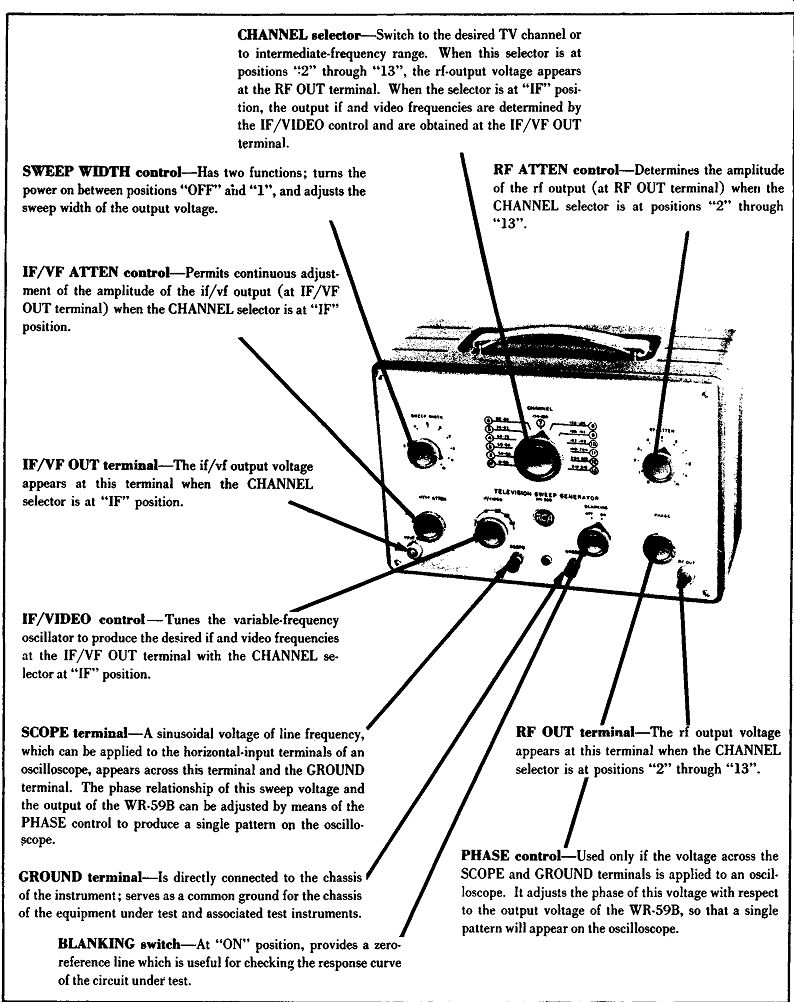
Figure 33. Another Sweep Generator in Which the Various Frequencies are Selected
by Means of a Switch. Courtesy of RCA.
---------------------
FIXED FREQUENCY GENERATOR
A somewhat different approach to FM & TV generator design is illustrated by the instrument s how n in Figure 32. Here, the various sweep frequencies required for the alignment and adjustment of television receiver circuits are obtained from certain fixed positions of a selector switch rather than by the more conventional continuous frequency dial.
The front panel of this instrument contains two large selector switches, one labeled "Sweep Selec tor," and the other "Video Selector." The various positions of the "Sweep Selector" switch are as follows:
Channel Frequency Band Width
A 4.5 mhz 1 mhz B 10. 7 mhz 2 mhz C 100. mhz 2 mhz D 20-24 mhz 4 mhz E 20-28 mhz 8 mhz F 38-48 mhz 10 mhz 2 54-60 mhz 10 mhz 3 60-66 mhz 10 mhz 4 66-72 mhz 10 mhz 5 76-82 mhz 10 mhz 6 82-88 mhz 10 mhz 7 174-180 mhz 10 mhz 8 180-186 mhz 10 mhz 9 186-192 mhz 10 mhz 10 192-198 mhz 10 mhz 11 198-204 mhz 10 mhz 12 204-210 mhz 10 mhz 13 210-216 mhz 10 mhz Sweep width is variable on each channel from zero to the maximum indicated above. Each channel is calibrated on the single frequency indicated or in the middle of the range indicated with the " Sweep Width" control turned to zero. Channels" A," "B," & " C" are provided with air trimmers for calibration.
On the other side of the panel, the "Video Selector" control selects the output frequency of the video carrier oscillator in any of the standard channel ranges. Thus, for Channel 2, 54-60 mhz, the video carrier frequency is 55.25 mhz; etc. Normally, the output of the video carrier oscillator is unmodulated.
However, any external signal having a frequency from 5 cycles to 5 megacycles can be used to modulate the carrier. The modulating signal would be fed into the generator at the "Video Input" term in a 1 and the modulated video carrier signal obtained at the outlet marked "Video-Marker Output." This latter signal can be fed to the antenna of a receiver and if it is properly modulated, can be substituted as a miniature TV station in place of regular broadcasts. This is a desirable servicing feature that is especially valuable in areas where signals are weak, unreliable, or are available only during limited periods of the day. (A suitable source of video signals will be described in the section on Special Test Instruments.) At the end of the" Video Selector" switch there are two positions marked "X" and "Y." In the "X" position a marker generator is activated and its output appears at the "Video-Marker Output" terminal. The frequency range in the "X" position is 19 to 31 mhz; in the "Y" position it is 31 to 50 mhz.
The desired frequency in either of these ranges is selected on a 3-inch dial in the center of the panel.
The generator also contains a crystal oscillator whose frequency is determined by an external plug-in crystal. This oscillator is separate from the marker oscillator and thus makes it possible to obtain two markers at the same time by using a crystal of the desired frequency and setting the marker oscillator to the other desired frequency.
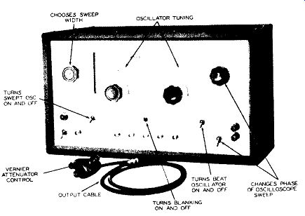
Figure 34. A Variable Permeability Sweep Generator. Courtesy of General Electric.
Another sweep generator wherein the various frequencies are obtained by means of a selector switch is the unit shown in Figure 33. Sweep frequencies for each of the twelve channels are available plus an IF position where a variable frequency oscillator produces signals from 0.3 to 50 mhz. The operating frequency within this 0.3-50 mhz range is selected by the "IF Video" knob. The markings on this control are only approximate since precise determination of any frequency in the response curve swept out is accomplished by a separate marker generator.
The maximum sweep width for the RF and IF positions is 10 mhz.
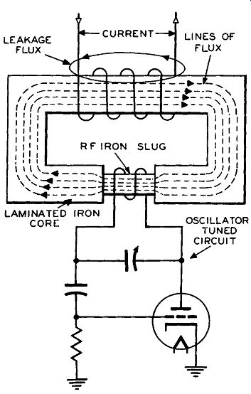
Figure 35. The Basic Modulator and Oscillator Circuit Used in the G.E. Variable
Reluctance Generator.
VARIABLE PERMEABILITY SWEEP GENERATOR
In the most sweep generators, the periodic variations infrequency are achieved either by electro mechanical means or by a reactance tube. In the sweep generator shown in Figure 34, still another method is employed, one known as the variable permeability or the variable reluctance method.
The basic circuit employed is shown in Figure 35. An iron core choke is constructed with a wide gap and a small piece of powdered iron is placed across this gap. The tuning coil of the oscillator is then wound around this iron slug and whatever affects the permeability of the iron slug will automatically serve to alter the frequency generated by the oscillator.
When current is sent through the main choke winding, lines of flux are established in the iron core of the choke in the manner shown in Figure 35. Note that the lines of flux are more concentrated in the powdered iron slug than they are in the laminated iron core. Increasing the current through the choke winding will cause the lines of flux in both the laminated iron core and the powdered iron slug to increase in like measure. However, since the flux lines are more concentrated in the iron slug, their effect in altering the permeability of this iron section will be greatest. By applying a 60-cycle voltage to the main choke coil, we can force the slug permeability to vary in a similar manner and since the oscillator coil is wound around this slug, its frequency will vary, too.
Since the flux changes 60 times a second, the frequency of the oscillator will shift back and forth at the same rate and we have achieved frequency modulation. (For those readers who wish a more detailed description of this method of frequency modulation, reference should be made to the May, 1950 issue of Radio and Television News Magazine, P. 48.) The sweep oscillator (or swept oscillator, as the manufacturer labels this stage) consists of a 6J6 dual triode with both sections paralleled as a modified Colpitts oscillator tuneable through a range of 165 to 220 mhz. A series of voltage taps from the secondary of the power transformer allows the operator to select several widths of sweep output by means of the "Sweep Width'' selector switch shown in Figure 34.
Available sweep widths are as follows:
"Sweep Width" Control Position 1 * 2 3 4 5 6 7
Approx. Width
0 500 khz 4.5 mhz 2 mhz 9 mhz 14 mhz 19 me
In position 1, the sweep oscillator functions as a simple AM generator producing frequencies over ...
* Maximum counter clockwise.
... the range from 165 to 220 mhz, depending on the setting of the oscillator variable capacitor. A front panel calibrated dial is provided for this purpose.
This generator will also cover the range from 4 mhz to 110 mhz and this is accomplished by beating another oscillator against the sweep oscillator. (See Figure 36.) The second or beat oscillator is tuneable from 220 mhz through 275 mhz. To cover the frequencies from 55 to 110 mhz, the beat oscillator is left at 275 mhz and the sweep oscillator is varied throughout its range from 165 to 220 mhz. 275 mhz minus 165 mhz equals 110 mhz and 275 minus 220 mhz equals 55 mhz.
Hence the range from 55 to 110 mhz is covered. The difference frequencies of the two oscillators are pro duced in a mixer and fed through an attenuator to the front panel.
The generator is also capable of developing voltages having frequencies born 4 mhz to 55 mhz.
This is achieved by tuning the sweep oscillator to 220 mhz and varying the beat oscillator over its range from 220 mhz to 275 mhz. The lowest output frequency which can be reached is 4 mhz because when the beat oscillator approaches 220 mhz, it has a tendency to lock in with the sweep oscillator and the frequency drops sharply to zero. Because of this, it is difficult (if not impossible) to obtain any frequencies below 4 mhz.
The output attenuator in this instrument is in five steps, x 1, x .1, x .01, x .001, dnd x .0001. The strongest output would be obtained from the x 1 connector. Instead of using a selector switch to achieve the desired output level, there is a separate front panel connector for each level output. The RF output cable is plugged into whatever connector is desired.
Another feature of interest is the placement of the RF output potentiometer at the terminal end of the output cable. This attenuator control can be partially seen in Figure 34: it is shown by itself in Figure 37. The knob at the top of the unit is connected to the shaft of the potentiometer. Either balanced or unbalanced output arrangements are available.
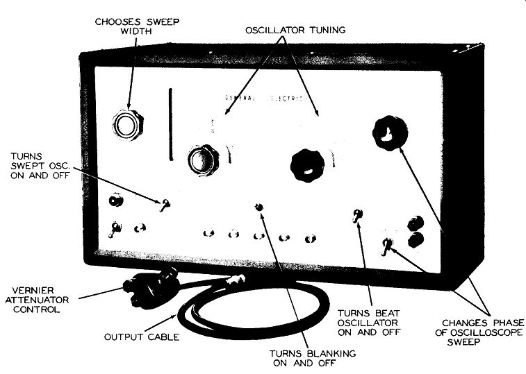
Figure 34. A Variable Permeability Sweep Generator. ( Model ST-4A, Courtesy
of General Electric Co.)

Figure 35. The Basic Modulator and Oscillator Circuit Used in the G.E. Variable
Reluctance Generator.
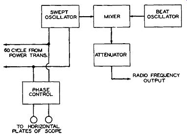
Figure 36. A Block Diagram (Simplified) of the G.E. Sweep Generator.
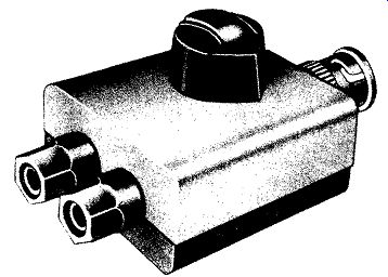
Figure 37A. The Output Adaptor Which Converts the Single-Ended Output of the
G.E. Sweep Generator to a Balanced Output for Working Into a 300-Ohm Resistive
Load.
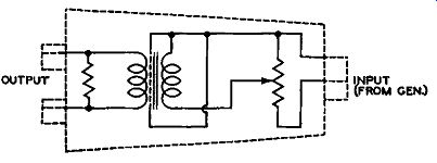
Figure 37B. Schematic Diagram of the Output Adaptor.
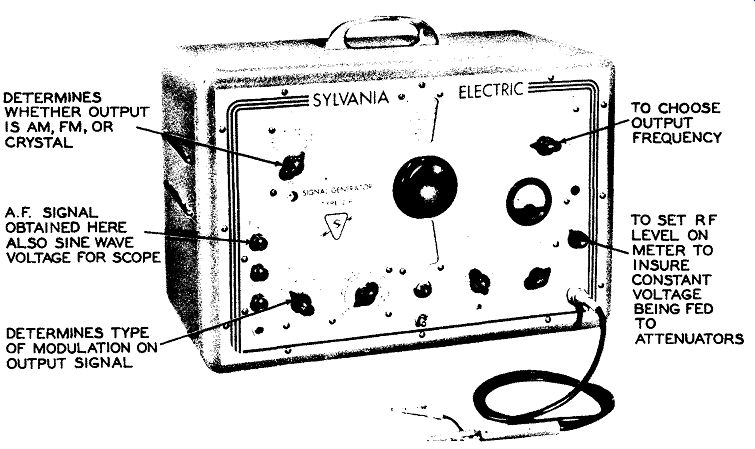
Figure 38. A Sweep Generator Designed Primarily for AM -FM Application, Although
it can be Employed for Peaking of TV Circuits. Courtesy of Sylvania Electric
Products, Inc.

Figure 38. A Sweep Generator Designed Primarily for AM-FM Application, Although
it Can Be Employed for Peaking of TV Circuits. (Model 216, Courtesy of Sylvania
Electric Products Inc.)
Most of the remaining controls on the front of this sweep generator are similar to controls on other instruments which have a Ir e ad y been discussed.
Thus, there is a phase control, a phase reversal switch, and a blanking switch. Terminals are provided, too, for feeding a portion of the 60-cycle sweep voltage to the oscilloscope. Finally, an "Output To Marker" jack permits a portion of the RF output voltages to be fed to a separate marker generator also manufactured by the same company. Just what is accomplished by this will be see n presently when marker generators are discussed in the section on Special Test Instruments.
AM-FM GENERATORS
Sweep generators, in general, are designed to be used with FM or TV receivers. This particular combination is a natural one since all television receivers contain an FM sound section and the allocated RF frequencies for the FM broadcast band, 88-108 mhz, falls between the low and the high band television channels.
There are , however, a number of generators available that are meant to be used primarily with AM FM receivers only. These instruments are usef1..: for those shops that concentrate chiefly on AM or FM receiver servicing with little or no work in the TV line. Such instruments are, aIso useful in those localities where there is no television.
An AM - FM generator that will illustrate the type of controls found on such instruments is shown in Figure 38. The functions of some of these controls will be recognizable immediately from previous discussions. Thus, the "RF Amplitude "control smoothly varies the RF output of the generator from zero to whatever le v el is established by the '' RF Attenuator'' switch. This lowest position of this latter control is at the " 10 K" point. The highest is at the "1" position.
The "Range" select or switch, in the upper right-hand corner, establishes the band of frequencies generated by the instrument. There are seven bands listed, extending from 80 khz at the low end to 60 mhz at the high end. 60 mhz, however, is not the highest frequency that can be obtained from the generator and the reason for this will be seen from the following description of the generator circuitry.
CIRCUIT DESCRIPTION
Basically, there are two oscillators in this generator. One is continuously variable from 80 khz to 60 mhz by means of a tuning dial and the "Range" selector switch, and its frequency is r e ad directly from the dial, in black figures. The other oscillator may operate at either 1 mhz or 60 mhz depending on the setting of the "Output selector" switch. It may be amplitude modulated or frequency modulated, depending on the setting of the "Circuit Selector" and the "Output Selector" switches. 400 cycle internal amplitude modulation, 0 to 100%, is available, using the AM CW setting of the '' Output Selector'' switch and the 400 AM position of the "Circuit Selector" control.
60 cycle frequency modulation is available on the 60 mhz and 1 mhz fixed oscillators, and 400 cycles on the 60 mhz oscillator. The percentage modulation (for AM) or frequency deviation (for FM), is controlled by rotating the "Modulation" knob.
The outputs of the variable oscillator and the modulated fixed oscillator are combined in a mixer tube, when FM sweeps are used, and therefore the signal generator output under these conditions is a combination frequency of the two. Hence, to get the frequency of the output of the signal generator, it is necessary to add or subtract the frequency of the fixed oscillator (either 1 mhz or 60 mhz) and the direct dial reading. The most frequently used FM frequencies are marked in red figures on the dial. More on this point presently.
In addition to the two RF oscillators, the signal generator contains an audio oscillator which furnishes a 400-cycle audio signal for external use. It also contains a heterodyne detector, and provision for a 1 mhz crystal. The crystal is not furnished with the signal generator, but can be purchased separately.
The output of the mixer tube in the signal generator is applied across an attenuator system possessing continuous and step attenuators. The output will vary considerably across the frequency range of the signal generator, and for this reason there is a meter connected across this point, so that the voltage across the attenuators may be kept constant at all times. The "RF Set" knob is used to keep this voltage constant at some arbitrary point about 6 on the meter. The "RF Set" control is not to be used to vary output; this is the function of the attenuators. If higher voltages are required for badly adjusted receivers, a " HI-RF" jack provides about 1.0 volt signal, with an impedance of 500 ohms. The impedance of the coax lead at the regular " RF" outlet is 50 ohms.
The controls on this instrument which would give the serviceman the greatest amount of trouble are the "Output Selector" , "Circuit Selector" , and "Modulation" controls. The following detailed description showing how the generator is set up to deliver AM and FM signals will help to clarify their application.
OPERATION
A. To obtain Unmodulated RF (CW).
1. Set " Range " switch to the desired band and the tuning dial to the desired frequency.
2. Set "Circuit Selector" to CW.
3. Set "Output Selector" to AM - CW.
4. Set the "RF Set" control so that the meter reads 6.
5. Set the "RF Attenuator" switch and the "RF Amplitude" control to desired out put. Maximum output will be delivered when the "RF Attenuator" is set to 1, and the "RF Amplitude" control is at the maximum clockwise position.
6. Connect test Ieads of the RF coaxial cable to circuit under test. Connect the metal shield to chassis ground.
When AC, DC receivers are being tested, an isolation transformer· is inserted between the receiver and the AC line. If such a transformer is not avail able, then a 400 volt .01 mfd blocking capacitor should be connected between the signal generator ground and the receiver chassis.
The center lead of the coaxial cable should be isolated from the test point if a DC voltage is present here. Use a 400 volt .01 mfd. capacitor when using frequencies up to 1500 khz. Above this point a smaller capacitor may be used.
With the RF meter set to a constant reference level, the voltage across the attenuator system will be constant, regardless of frequency. To control the amount of signaI in the coaxial cable, the "RF Attenuator'' control will reduce the signal by multiples of 10 step-by-step, and the" RF Amplitude" control will permit smooth adjustment of the resultant signal, from zero to maximum. Maximum RF signal is available when the attenuators are set for maximum output, but the s e attenuators are not designed to control the "HI-RF." · B. To obtain Amplitude Modulated Output.
1. With internal modulation (0-100%, 400 cycles.) (a) Settings s a mhz as those in the unmodulated CW output case, except that "Circuit Selector" switch is turned to "400 .... AM" and the "Modulation" control is rotated clockwise to the de sired percentage of modulation (Figure 39 A). The modulation control has four ranges but the only one of interest in the present set-up is the scale marked "% AM 400~.
2. With External Modulation.
(a) Settings s a mhz as those in (1), except that the "Circuit Selector" switch is set to" Ext. Mod." An external audio signal may then be connected between " Ext. Mod." binding post and ground.
The external modulating frequency may be anywhere in range of 50 to 12,000 cycles. About 38 volts rms will produce 100% modulation.
3. The modulation control is calibrated to ± 5% at the 30% (standard AM test modulation) point.
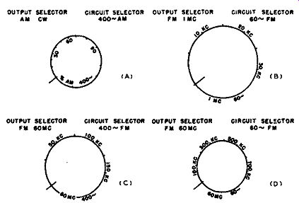
Figure 39. Modulation Dial Detail of Sylvania AM-FM Generator.
C. To use the Heterodyne Detector. *
1. Set the "Circuit Selector" switch to "Det." position, and turn the "RF Amplitude" control to 0, reducing signal at "RF" terminal.
2. Plug in a pair of headphones, preferably high impedance, into the" Phones" jack.
3. Set " Range " switch to desired band and tuning dial to desired frequency.
4. Apply the external signal between the "RF IN" jack and ground. The amplitude of the external signal should be at least 0.1 volt for best results. Do not apply an external signal of greater than 50 volts RF, or having a DC component of greater than 400 volts. When the frequency of the external s i g n a I and the signal generator coincide, a beat note will be heard in the headphones. At zero beat, the frequency on the signal generator dial is the same as the frequency of the external signal. Care should be taken that harmonics of either signal are not confused with the fundamental frequencies. Always use the signal which supplies the strongest beat note.
* Another name for beat detector. In this instrument a 1N34 germanium crystal is the detector.
The heterodyne detector affords the serviceman a method of checking the frequencies of unknown signals that fall within the range of this instrument.
D. To Obtain Audio Output.
1. Set "Circuit Selector" switch to "400 ,,., AM" position and take off audio voltage between "AF Out" and "Ground" binding posts.
2. The audio output voltage at 400 cycles is 1.3 volts.
E. To Obtain Narrow Band FM Output for Testing AM Receivers.
1. Set the "Output Selector" switch to "FM 1 mhz."
2. Set the tuning di al to the IF frequency desired, reading the red dial figures (0-600 khz). If other frequencies are desired they may be obtained by setting the black dial figures 1 mhz higher than the desired center frequency.
3. By means of the "RF Set" control, a just the output meter to a chosen reference level (about 6 on the meter scale).
4. Set the "Circuit Selector" switch to "60,-,FM," and turn the modulation control to the sweep width required. (See Figure 39B).
5. The modulation control scale is calibrated to a ± 5% at the 30 khz point.
This particular setting of the generator controls enables the serviceman to see the entire response curve of the tuning circuits of an AM receiver. (This operation is .seldom performed because simple peaking using an AM generator and a VTVM will normally be sufficient. However, if a visual alignment is desired, this generator will furnish the necessary sweep signal.) The red figures on the dial are used since they represent the frequencies derived from the signal mixing of the variable oscillator and the fixed 1 mhz FM oscillator. Where the frequency desired is not given in red,. turn the di al until its value is 1 mhz higher than the frequency you wish. For example, if you want an FM signal of 8.5 mhz, and this is not given in red, then set the scale to read 9.5 mhz. This frequency mixed w it h the 1 mhz FM o s c ill at or will provide, at the output a difference frequency of 8.5 mhz. (There will, of course, also be present the sum frequency of 10.5 mhz which can also be used if it is needed.) For this setting of the instrument controls, the "1 mhz, 60 "scaIe of the "Modulation" control would be employed to set the desired sweeping range.
The maximum sweep indicated is 30 khz.
F. To Obtain Wide Band FM Output for Testing FM Receivers.
1. Set the " Output Selector" switch to FM 60 mhz. This brings in the 60 mhz FM oscillator and mixes its output with that of the variable oscillator.
2. Set the tuning dial to the IF or RF frequency desired, reading the red dial figures. Frequencies other than those shown in the direct reading red scale have to be obtained by making your own computations, as follows:
(a) Frequencies lower than 60 mhz: Set the black dial figures to a reading 60 mhz higher than the desired output frequency.
(b) Frequencies higher than 60 mhz: Set the black dial figures to a reading 60 mhz lower than the desired output frequency.
The reason for this procedure stems from the fact that to obtain signals below 60 mhz, we are using the difference frequencies produced by the mixing of the two oscillator signals. Therefore, the black figures are set to a value 60 mhz above the desired frequency. If 15 mhz is required, mixing 75 mhz from the vari able oscillator (given in black figures) with the fixed 60 mhz from the FM oscillator will give us what we want. On the other hand, to obtain signals above 60 mhz, we use the sum frequencies from the two oscillators.
3. Adjust the output meter to a reference level of about 6.
4. Set the "Circuit Selector" switch to 60 cycles FM, and turn the "Modulation" control to the sweep width desired.
Maximum sweep available is 700 khz. (Plus 350 khz and minus 350 khz.) 60 cycles FM means that the frequency modulation is occurring at a 60 cycle rate. This is similar to the 60 cycle sweeping of the frequency in the TV generators previously discussed in this section.
When the generator of Figure 38 is being used to sweep out a response curve of an FM receiver, 60 cycle sine wave sweeping voltage for the oscilloscope is obtained from the terminal marked ''AF Out (Sync)''. There is also available on this generator a 400 cycle FM position where the frequency modulating or frequency sweeping is occurring at a 400 cycle rate instead of the more conventional 60 cycle rate. This is done so that the serviceman will have a source of FM output which can be used for checking the overall performance of an FM receiver for distortion. When this 400 cycle FM modulated signal is fed into the mixer of an FM receiver, for example, and passed through the IF system, FM detector, and audio stages then a 400-cycle note will be heard in the speaker.
By means of an oscilloscope connected even as far down the line as the voice coil of the receiver, you can observe any distortion of the 400 cycle modulation which might have crept in at some point in the receiver through which the signal has passed.
Further, by sending the FM signal through the entire receiver, a check of distortion from antenna to voice coil can be made.
Of course, 60 cycle FM modulation might also be used in the same manner although a 400 cycle note is easier to work with (i.e., listen to) than the raspy 60 cycles.
In the generator of Figure 38, a 400 cycle sine wave voltage for the horizontal input terminals of the oscilloscope is available at the" AF Out (Sync)" post when the "Circuit Selector" switch is in the "400 FM" position.
G. External Modulation.
1. With the "Output Selector" switch set on either " FM 1 mhz," " AM CW," or "FM 60 mhz," the "Circuit Selector" may be set to" Ext. Mod." and the signal then will be modulated by any audio frequency signal applied between the " Ext. Mod." binding post and the "Ground" binding post, providing it is in the frequency range between 50 and 12,000 cycles. At other frequencies some modulation may be obtained, but possibly not the full amount. When using external modulation, the "Modulation" control should be turned fully clockwise, to prevent loading the signal source.
H. Very High Frequencies.
Due to the fact that harmonics are present in the output of all oscillators, a second harmonic of the AM CW oscillator will furnish output up to 120 megacycles, with some output even at higher frequencies.
These harmonics can be made use of in aligning the short wave sections of AM receivers going above 60 mhz, and their frequency is simply twice the frequency indicated on the calibrated dial. Considerable energy is present eve n at TV RF frequencies, and an AM signal may be used to produce bar patterns on picture tubes.
When the outputs of the sweep oscillator and the variable oscillators are combined, as in the procedure when FM signals are being used, numerous harmonics are available. The sum and difference frequencies will be quite strong, and their harmonics will be strong enough for most alignment work. This makes it possible to obtain useable signals up to 240 megacycles. The frequency is read by adding 60 mhz to the dial reading, and multiplying the sum by two.
Visual alignment of the video RF or video IF stages of a television receiver is not possible because the maximum frequency s w in g obtainable from this instrument is only 700 khz. However, visual alignment of the sound IF stages of a television receiver can be carried out.
I. To Check or Calibrate, Using an Internal Crystal.
1. Turn" Output Selector" to" Xtal 1 mhz," and "Circuit Selector" to "Oet."
2. Plug headphones into phone jack, and turn dial for zero beat. Beats will be found for the fundamental and large number of harmonics of the crystal frequency. An external lead may be run from the '' Xtal Output'' to the '' RF IN" jack to pick up weaker harmonics for higher frequency comparisons.
HICKOK AM-FM GENERATOR
An AM - FM generator which is somewhat more elaborate than the foregoing instrument is shown in Figure 40. This contains, in addition to the signals provided by the previous generator, an audio signal capable of being varied between 0 and 15 khz, dual frequency crystal control, and an output or db meter.
The crystal oscillator can provide output frequencies of either 100 khz or 1000 khz and harmonics of each so that appropriate points may be checked all along the frequency dial.
The decibel (db) meter consists of a conventional copper oxide rectifier and its associated meter. The meter may be used to measure output voltage ranging from zero to 140 volts or decibel power levels ranging from -10 db to 38 db. As all of the db meter scales are calibrated on the basis of 0 db = .006 watts (6mw} when used across a 500-ohm termination, the voltage re a dings and db readings correspond only when the meter is connected across a 500-ohm termination. There is a blocking capacitor in the decibel meter for circuits having a DC component.
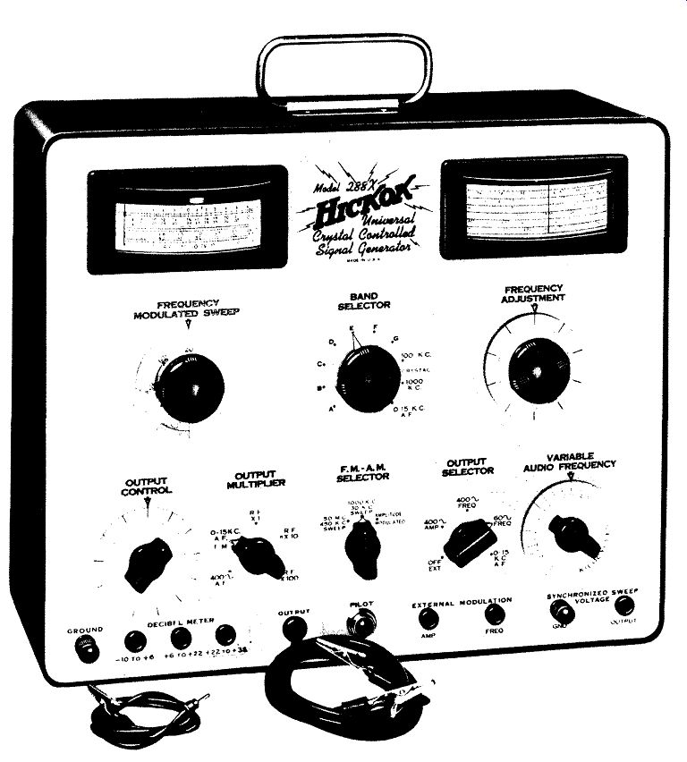
Figure 40. Another Sweep Generator Designed Principally for AM-FM Application.
(Model 288, Courtesy of Hickok Electrical Instrument Co.)
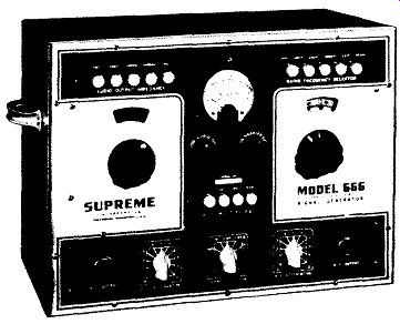
Figure 41. A Push-button Type of Signal Generator. Courtesy of Supreme Instrument
Co.
A brief description of the various controls on this instrument will indicate their function.
A. " Frequency Modulated Sweep" -- A dual purpose control which is used as the AC line power switch and also as a control of the bandwidth of the sweep for frequency modulated output. To place the instrument in operation, turn the control clock wise until the line switch is closed which will be indicated by an audible click and the lighting of the pilot light. The position of this control, when not operating as a bandwidth sweep control, has no effect on the operation of the instrument.
B. "Band Selector" -- A ten-position control; The first seven positions, Bands "A" through "G," select various frequency ranges from 100 khz to 110 mhz, the next two positions select either the "100 khz" or "1000 khz" crystal frequency and the last position selectsthe"0-15 khz" audio frequency. (Note that 1000 khz is equal to 1 mhz.)
C. "Frequency Adjustment" -- Control of the frequency within the range selected by the " Band Selector" switch. Calibration of the dial permits interpolation of the scale if desired.
D. "Output Control" -- Linear potentiometer control of the RF and AF output voltage of the signal generator.
E. "Output Multiplier" - A five-position control of the output of the signal generator. Positions "RF x 1," "RF x 10, "and" RF x 100" are the three output levels of RF signal. Positions "0-15 khz AF FM," in conjunction with the "Output Selector" switch, selects either the 0-15 khz audio frequency output or any of the frequency modulated outputs.
Position "400 AF" selects the 400 cycle audio voltage as an audio signal or for amplitude modulation.
F. "FM - AM Selector" - A three position control.
1. " Amplitude Modulated" for all outputs other than frequency modulated outputs.
2. "1000 khz 30 khz Sweep" for the 1000 khz signal frequency modulated with a band width of 0-30 khz.
3. "50 mhz 450 khz Sweep" for the 50 mhz signal frequency modulated with a band width of either 0-150 khz or 0-450 khz.
F. "Output Selector" - A five position switch selecting the various types of outputs.
1. "Off Ext." for unmodulated radio frequency output or either frequency or amplitude modulation from an external source.
2. "400,.. AMP" for 400 cycle amplitude modulation and for a 400 cycle, fixed audio frequency signal.
3. "400_ Freq." for 400 cycle modulating frequency used for frequency modulating the 50 mhz, 0-15 khz sweep output.
4. "60 Freq." for 60 cycle modulating frequency used for frequency modulating either the "1000 khz -30 khz sweep," or " 50 mhz -450 khz sweep," output.
5, "0-15 khz AF" for an audio frequency variable from 0 to 15 khz.
H. "Variable Audio Frequency''-- A calibrated variable control of the audio frequency output from 0 to 15 kilocycles.
I. "Synchronized Sweep Voltage" ("Gnd Output" ). Output connections for a 60 cycle voltage from the power supply for supplying the horizontal sweep of an oscilloscope. Note that a 400 cycle sine wave voltage is not available for deflecting the scope beam.
If it should be desired to use the 400 cycle FM for developing response curves, it would be necessary to go internally into the instrument to obtain the 400 cycle audio source to be used simultaneously with the 400 cycle FM output. Without this change, response curves must be obtained using the 60 cycle FM sweep.
J. "External Modulation (Amp-Freq.)" - Amp: permitting amplitude modulation connection from an external source. Freq: permitting frequency modulation connection from an external source.
K. "Pilot" -- Indication of power being supplied the signal generator.
L. "Output" -- Attached shielded output cable for the output signal.
M. "Decibel Meter" -- (- 10 to +6, +6 to +22, +22 to +38) -- pin jacks for connection to the combination AC voltage and decibel meter at one of the three ranges available.
N. "Ground" - Binding post for connecting the ground of the signal generator to that of any associated equipment; also the ground connection for the "Decibel Meter." Before we leave the subject of AM -FM generators, we might note the unit shown in Figure 41.
In place of a selector switch for choosing the RF band, push buttons are employed. To choose a certain band, the appropriate push button is depressed. The exact frequency, then, within this band is obtained by rotating the dial to the proper position.
Similar push buttons are available for the '' RF Multiplier" and the "Audio Output Impedance." The latter is a special transformer in the audio frequency section which offers the serviceman a choice of four selected impedances to match the input of P-A amplifiers, motion picture sound equipment, inter-department communications systems, etc. Audio frequencies from 15 to 15,000 cycles are available.