|
|
__1 Introduction
Many audio professionals think of system grounding as a black art. How many times have you heard someone say that a cable is picking up noise, presumably from the air like a radio receiver? Even equipment manufacturers often don't have a clue what's really going on when there's a problem. The most basic rules of physics are routinely overlooked, ignored, or forgotten. As a result, myth and misinformation have become epidemic! This Section is intended to enable sound engineers to understand and either avoid or solve real world noise problems. The electronic system engineering joke that cables are sources of potential trouble connecting two other sources of potential trouble contains more truth than humor. Because equipment ground connections have profound effects on noise coupling at signal interfaces, we must appreciate how interfaces actually work as well as when, why, and how equipment is grounded. Although the subject can't be reduced to just a few simple rules, it doesn't involve rocket science or complex math either.
For convenience in this section, we'll use the term noise to mean to signal artifacts that originate from sources external to the signal path. This includes hum, buzz, clicks, or pops originating from the power line and interference originating from radio-frequency devices. A predictable amount of white noise is inherent in all electronic devices and must be expected. This random noise, heard as hiss, will also limit the usable dynamic range of any audio system, but this is not the subject of this section! Any signal accumulates noise as it flows through the equipment and cables in a system. Once it contaminates a signal, noise is essentially impossible to remove without altering or degrading the signal. Therefore, noise and interference must be prevented along the entire signal path. It might seem trivial to transfer signal from the output of one audio device to the input of another but, in terms of noise and interference, signal interfaces are truly the danger zone! Let's start with some basic electronics that apply to interfaces.
__2 Basic Electronics
Fields can exert invisible forces on objects within them.
In electronics, we're concerned with electric and magnetic fields. Almost everyone has seen a demonstration of iron filings sprinkled on paper used to visualize the magnetic field between the north and south poles of a small magnet. A similar electric field exists between two points having a constant voltage difference between them. Fields like these, which neither move nor change in intensity, are called static fields.
If a field, either magnetic or electric, moves in space or fluctuates in intensity, the other kind of field will be generated. In other words, a changing electric field will set up a changing magnetic field or a changing magnetic field will set up a changing electric field. This interrelationship gives rise to electromagnetic waves, in which energy is alternately exchanged between electric and magnetic fields as they travel through space at the speed of light.
Everything physical is made of atoms whose outer most components are electrons. An electron carries a negative electric charge and is the smallest quantity of electricity that can exist. Some materials, called conductors and most commonly metals, allow their outer electrons to move freely from atom to atom. Other materials, called insulators and most commonly air, plastic, or glass, are highly resistant to such movement.
This movement of electrons is called current flow.
Current will flow only in a complete circuit consisting of a connected source and load. Regardless of how complex the path becomes, all current leaving a source must return to it!
__2.1 Circuit Theory
An electric potential or voltage, sometimes called emf for electromotive force, is required to cause current flow. It is commonly denoted E (from emf) in equations and its unit of measure is the volt, abbreviated V. The resulting rate of current flow is commonly denoted I (from intensity) in equations and its unit of measure is the ampere, abbreviated A. How much current will flow for a given applied voltage is determined by circuit resistance. Resistance is denoted R in equations and its unit of measure is the ohm, symbolized “omega”.
Ohm's Law defines the quantitative relationship between basic units of voltage, current, and resistance:
E= IR
…which can be rearranged as…
R = E/I
For example, a voltage E of 12 V applied across a resistance R of 6-ohm will cause a current flow I of 2 A.
Circuit elements may be connected in series, parallel, or combinations of both, Figs. 1 and 2.

Figure 1. The voltage is the same across all elements in a parallel circuit.

Figure 2. The current is the same through all elements in a series circuit.
Although the resistance of wires that interconnect circuit elements is generally assumed to be negligible, we will discuss this later.
In a parallel circuit, the total source current is the sum of the currents through each circuit element. The highest current will flow in the lowest resistance, according to Ohm's Law. The equivalent single resistance seen by the source is always lower than the lowest resistance element and is calculated as:
 (1)
(1)
In a series circuit, the total source voltage is the sum of the voltages across each circuit element. The highest voltage will appear across the highest resistance, according to Ohm's Law. The equivalent single resistance seen by the source is always higher than the highest resistance element and is calculated as (2)
Voltages or currents whose value (magnitude) and direction (polarity) are steady over time are generally referred to as dc. A battery is a good example of a dc voltage source.
__2.2 AC Circuits
A voltage or current that changes value and direction over time is generally referred to as ac. Consider the voltage at an ordinary 120 V, 60 Hz ac receptacle.
Since it varies over time according to a mathematical sine function, it is called a sine wave. Figure 3 shows how it would appear on an oscilloscope where time is the horizontal scale and instantaneous voltage is the vertical scale with zero in the center. The instantaneous voltage swings between peak voltages of +170 V and -170 V. A cycle is a complete range of voltage or current values that repeat themselves periodically (in this case every 16.67 ms). Phase divides each cycle into 360 deg.and is used mainly to describe instantaneous relationships between two or more ac waveforms.
Frequency indicates how many cycles occur per second of time. Frequency is usually denoted f in equations, and its unit of measure is the hertz, abbreviated Hz.
Audio signals rarely consist of a single sine wave. Most often they are complex waveforms consisting of many simultaneous sine waves of various amplitudes and frequencies in the 20 Hz to 20,000 Hz (20 kHz) range.
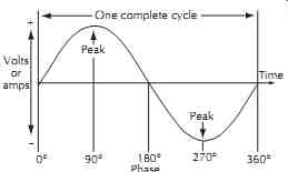
Figure 3. Sine wave as displayed on an oscilloscope.
__2.3 Capacitance, Inductance, and Impedance
An electrostatic field exists between any two conductors having a voltage difference between them. Capacitance is the property that tends to oppose any change in the strength or charge of the field. In general, capacitance is increased by larger conductor surface areas and smaller spacing between them. Electronic components expressly designed to have high capacitance are called capacitors. Capacitance is denoted C in equations and its unit of measure is the Farad, abbreviated F. It's very important to remember that unintentional or parasitic capacitances exist virtually everywhere. As we will see, these parasitic capacitances can be particularly significant in cables and transformers! Current must flow in a capacitor to change its voltage. Higher current is required to change the voltage rapidly and no current will flow if the voltage is held constant. Since capacitors must be alternately charged and discharged in ac circuits, they exhibit an apparent ac resistance called capacitive reactance. Capacitive reactance is inversely proportional to both capacitance and frequency since an increase in either causes an increase in current, corresponding to a decrease in reactance.
where,
XC is capacitive reactance in ohms,
f is frequency in hertz,
C is capacitance in farads.
In general, capacitors behave as open circuits at dc and gradually become short circuits, passing more and more current, as frequency increases.
As shown in Figure 4, a magnetic field exists around any conductor carrying current at right angles to the axis of flow. The strength of the field is directly proportional to current. The direction, or polarity, of the magnetic field depends on the direction of current flow.
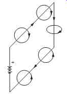
Figure 4
Inductance is the property that tends to oppose any change in the strength or polarity of the field. Note that the fields around the upper and lower conductors have opposite polarity. The fields inside the loop point in the same direction, concentrating the field and increasing inductance. An electronic component called an inductor (or choke) is most often made of a wire coil with many turns to further increase inductance. Inductance is denoted L in equations and its unit of measure is the henry, abbreviated H. Again, remember that unintentional or parasitic inductances are important, especially in wires!
If we abruptly apply a dc voltage to an inductor, a magnetic field is generated within the wire and moves outward as current begins to flow. But, in accordance with the law of induction, the rising field strength will induce a voltage, called back emf, in the wire which works to oppose current flow. The faster the field increases its strength, the more back emf will be Figure 4. Magnetic field surrounding conductor. induced to oppose current flow. The net result is to slow the buildup of current as it approaches its final value, which is limited by the applied voltage and circuit resistance. In ac circuits, for a constant applied voltage, this slowing reduces current flow as frequency increases because less time is available each cycle for current to rise. This apparent increase in ac resistance is called inductive reactance. Inductive reactance increases in direct proportion to both inductance and frequency.
...(4) where, XL is inductive reactance in ohms, f is frequency in hertz, L is inductance in henrys.
In summary, inductors behave as short circuits at dc and gradually become open circuits, passing less and less current, as frequency increases.
Impedance is the combined effect of both resistance and reactance for circuits that contain resistance, capacitance, and inductance, which is the case with virtually all real-world circuits. Impedance is represented by the letter Z and is measured in ohms. Impedance can be substituted for R in the Ohm's Law equations. Impedance is a more general term than either resistance or reactance and, for ac circuits is the functional equivalent of resistance.
__2.4 Single Wires
The electrical properties of wire are often overlooked.
Consider a 10 ft length of #12 AWG solid copper wire.
1. The resistance of a wire is directly proportional to its length, inversely proportional to its diameter, and depends strongly on the material. From standard wire tables, we find the dc resistance of #12 AWG annealed copper wire is 1.59-ohm/1000 ft or 0.0159-ohm for a 10 ft length. At frequencies below about 500 Hz, this resistance largely sets the impedance.
2. The inductance of a straight wire is nearly independent of its diameter but is directly proportional to its length. From the formula for the inductance of a straight round wire,1 we find its inductance is 4.8 µH. As shown in FIG. 5, this causes a rise in impedance beginning at about 500 Hz, reaching 30-ohm at 1 MHz (AM radio). Replacing the wire with a massive ½ inch diameter copper rod would reduce impedance only slightly to 23-ohm.
3. Electromagnetic waves travel through space or air at the speed of light. The physical distance traveled by a wave during one cycle is called wave length. The equation is
(5) where, M is wavelength in feet, f is frequency in MHz.
For 1 MHz AM radio, 100 MHz FM radio, and 2 GHz cell phone signals, wavelengths are about 1000 ft, 10 ft, and 6 inches, respectively.
4. Any wire will behave as an antenna at frequencies where its physical length is a quarter-wavelength or multiples thereof. This is responsible for the impedance peaks and dips seen at 25 MHz intervals in FIG. 5.
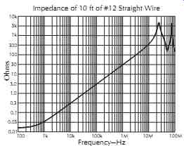
Figure 5. Wire is low-impedance current path only at low frequencies.
__2.5 Cables and Transmission Lines
A cable consists of two or more conductors that are kept in close proximity over their length. Cables, such as those for ac power and loudspeakers, are generally used to convey power to a load. In a pair of such conductors, because the same current flows to and from the load in opposite directions, the magnetic fields have the same intensity but are of opposite polarity as shown in FIG. 6. In theory, there would be zero external field, and zero net inductance, if the two conductors could occupy the same space. The cancellation of round trip inductance due to magnetic coupling varies with cable construction, with typical values of 50% for zip cord, 70% for a twisted pair, and 100% for coaxial construction.
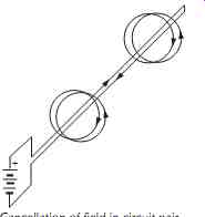
Figure 6. Cancellation of field in circuit pair.
At very high frequencies, a cable exhibits very different characteristics than it does at, say, 60 Hz power frequencies. This is caused by the finite speed, called propagation velocity, at which electrical energy travels in wires. It is about 70% of the speed of light for typical cables making wavelengths in cable correspondingly shorter. A cable is called electrically short when its physical length is under 10% of a wavelength at the highest frequency of interest. Wavelength at 60 Hz for typical cable is about 2200 miles (mi), making any power cable less than 220 mi long electrically short.
Likewise, the wavelength at 20 kHz for typical cable is about 34,500 ft, making any audio cable less than about 3500 ft long electrically short. Essentially identical instantaneous voltage and current exists at all points on an electrically short cable and its signal coupling behavior can be represented by lumped resistance, capacitance, and magnetically coupled inductance as shown in FIG. 7. Its equivalent circuit can then be analyzed by normal network theory.
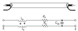
Figure 7. Lumped-circuit model of electrically short coaxial cable.
When a cable is longer than 10% of a wavelength, signals must be considered to propagate as electromagnetic waves and the cable can properly be called a transmission line. This includes typical cables longer than 7 ft for 10 MHz video, 8 inch for 100 MHz FM radio, and 0.8 inch for 1000 MHz CATV signals.
Significantly different instantaneous voltages exist along the length of a transmission line. For all practical purposes, its electrical equivalent is a distributed circuit consisting of a large number of small inductors and resistors in series and capacitors in parallel. If an electrical impulse were applied to one end of an infinitely long cable, it would appear to have a purely resistive impedance. This characteristic impedance of the cable is a result of its inductance and capacitance per unit length, which is determined by its physical construction.
Theoretically, the electrical impulse or wave would ripple down the infinite length of the cable forever. But actual transmission lines always have a far end. If the far end is left open or shorted, none of the wave's energy can be absorbed and it will reflect back toward the source. However, if the far end of the line is terminated with a resistor of the same value as the line's characteristic impedance, the wave energy will be completely absorbed. To the wave, the termination appears to be simply more cable. A properly terminated transmission line is often said to be matched. Generally, impedances of both the driving source and the receiving load are matched to the characteristic impedance of the line. In a mismatched line, the interaction between outgoing and reflected waves causes a phenomenon called standing waves. A measurement called standing-wave ratio (SWR) indicates mismatch, with an SWR of 1.00 meaning a perfect match.