|
|
.__3 Electronics of Interfaces
__3.1 Balanced and Unbalanced Interfaces
An interface is a signal transport subsystem consisting of three components: a driver (one device's output), a line (interconnecting cable), and a receiver (another device's input). These components are connected to form a complete circuit for signal current, which requires a line having two signal conductors. The impedances of the signal conductors, usually with respect to ground, are what determine whether an inter face is balanced or unbalanced. A concise definition of a balanced circuit is:
A balanced circuit is a two-conductor circuit in which both conductors and all circuits connected to them have the same impedance with respect to ground and to all other conductors. The purpose of balancing is to make the noise pickup equal in both conductors, in which case it will be a common-mode signal that can be made to cancel out in the load.
The use of balanced interfaces is an extremely potent technique to prevent noise coupling into signal circuits.
It is so powerful that many systems, including telephone systems, use it in place of shielding as the main noise reduction technique!
Theoretically, a balanced interface can reject any interference, whether due to ground voltage differences, magnetic fields, or capacitive fields, as long as it produces identical voltages on each of the signal lines and the resulting peak voltages don't exceed the capabilities of the receiver.
A simplified balanced interface is shown in FIG. 8. Any voltage that appears on both inputs, since it is common to the inputs, is called a common mode voltage. A balanced receiver uses a differential device, either a specialized amplifier or a transformer, that inherently responds only to the difference in voltage between its inputs. By definition, such a device will reject--i.e., have no response to-common-mode voltages. The ratio of differential gain to common-mode gain of this device is its common-mode rejection ratio, or CMRR. It's usually expressed in dB, and higher numbers mean more rejection. Section 5.1 will describe how CMRR often degrades in real-world systems and how it has traditionally been measured in ways that have no relevance to real-world system performance.

Figure 8. Basic balanced interface.
Two signal voltages have symmetry when they have equal magnitudes but opposite polarities. Symmetry of the desired signal has advantages, but they concern head room and crosstalk, not noise or interference rejection.
The noise or interference rejection property is independent of the presence of a desired differential signal.
Therefore, it can make no difference whether the desired signal exists entirely on one line, as a greater voltage on one line than the other, or as equal voltages on both of them. However, the symmetry myth is wide spread. A typical example is: Each conductor is always equal in voltage but opposite in polarity to the other.
The circuit that receives this signal in the mixer is called a differential amplifier and this opposing polarity of the conductors is essential for its operation. Like many others, it describes a balanced interface in terms of signal symmetry but never mentions impedances! Even the BBC test for output balance is actually a test for signal symmetry.
The idea that balanced interface is somehow defined by signal symmetry is simply wrong! It has apparently led some designers, mostly of exotic audiophile gear, to dispense with a differential amplifier input stage in their push-pull amplifiers. They simply amplify the (assumed) symmetrical input signals in two identical, ground-referenced amplifier chains. No mechanism exists to reject common-mode voltage (noise and interference) and it is actually amplified along with the signal, creating potentially serious problems. Rejection of common-mode voltages is the single most important function of a balanced receiver.
In an unbalanced circuit, one signal conductor is grounded (near-zero impedance) and the other has some higher impedance. As we will discuss in Section 5.4, the fact that not only signal but ground noise currents flow and cause voltage drops in the grounded conductor makes an unbalanced interface inherently susceptible to a variety of noise problems.
__3.2 Voltage Dividers and Impedance Matching
Every driver has an internal impedance, measured in ohms, called its output impedance. Actual output impedance is important, as we discuss below, but often absent from equipment specifications. Sometimes, especially for consumer gear, the only impedance associated with an output is listed as recommended load impedance.
While useful if listed in addition to output impedance, it is not what we need to know! A perfect driver would have a zero output impedance but, in practical circuit designs, it's neither possible nor necessary. Every receiver has an internal impedance, measured in ohms, called its input impedance. A perfect receiver would have an infinite input impedance but again, in practical circuit designs, it's neither possible nor necessary.
FIGs. 8 and 9 illustrate ideal interfaces. The triangles represent ideal amplifiers having infinite impedance input--i.e., draw no current-and zero impedance output--i.e., deliver unlimited current-and the line conductors have no resistance, capacitance, or inductance. The signal voltage from the driver amplifier causes current flow through the driver output impedance(s) Zo, the line, and receiver input impedance Zi.
Note that the output impedance of the balanced driver is split into two equal parts. Because current is the same in all parts of a series circuit and voltage drops are proportional to impedances, this circuit is called a voltage divider.
The goal of an interface is, with rare exception, to deliver maximum signal voltage from the output of one device to the input of another. Making Zi much larger than Zo assures that most of the signal voltage is delivered to the receiver and very little is lost in the driver. In typical devices, Zo ranges from 30-ohm to 1 k-ohm and Zi ranges from 10 k: to 100 k-ohm, which transfers 90-99.9% of the available--i.e., unloaded or open circuit-signal voltage.
Matching is a term that often causes confusion. A little math and Ohm's Law will prove that when Zo and Zi are equal, maximum power is transferred from source to load, although half the signal voltage is lost. If trans mission line effects apply, Zo and Zi must terminate or match the characteristic impedance of the line to prevent reflection artifacts. Although modern audio systems seldom use cables long enough for transmission line effects to apply or benefit from maximum power transfer, early telephone systems did both. Telephone systems began by using miles of existing open wire telegraph lines that, due to their wire size and spacing, had a characteristic impedance of 600-ohm . Since amplifiers didn't yet exist, the system was entirely passive and needed to transfer maximum power from one phone to another. Therefore, transformers, filters, and other components were designed for 600-ohm impedances to match the lines. These components were eventually incorporated into early sound reinforcement, radio, and recording systems. And the 600-ohm legacy still lives on, even though modern requirements for it are all but extinct.

Figure 9. Basic unbalanced interface.
Sometimes, instead of meaning equal, matching is used to mean optimizing some aspect of circuit performance. For example, the output transformer in a vacuum-tube power amplifier is used to optimize power output by converting or impedance matching the low-impedance loudspeaker to a higher impedance that suits the characteristics of the tubes. Similarly, the modern technique of making Zi much larger than Zo to transfer maximum voltage in signal interfaces is often referred to as voltage matching. It uses 10 k: or higher input impedances, called bridging because many inputs can be paralleled across the same output line with negligible drop in level. About 60-ohm has been suggested as the optimum Zo for driving up to 2000 ft of typical shielded twisted pair cable in these balanced interfaces.
3.3 Line Drivers and Cable Capacitance
A line driver and cable interact in two important ways.
First, output impedance Zo and the cable capacitance form a low-pass filter that will cause high-frequency roll-off. A typical capacitance for either unbalanced or balanced shielded audio cable might be about 50 pF/ft.
If output impedance were 1 k-ohm (not uncommon in unbalanced consumer gear), response at 20 kHz would be -0.5 dB for 50 ft, -1.5 dB for 100 ft, and -4 dB for 200 ft of cable. If the output impedance were 100-ohm (common in balanced pro gear), the effects would be negligible for the same cable lengths. Low-output impedance is especially important when cable runs are long. Also be aware that some exotic audio cables have extraordinarily high capacitance.
Second, cable capacitance requires additional high-frequency current from the driver. The current required to change the voltage on a capacitance is directly proportional to the rate of change or slew rate of the voltage. For a sine wave, (6) where, SR is slew rate in volts per second, f is frequency in hertz, Vp is peak voltage.
...(7) where, I is current in A, SR is slew rate in V/µs, C is capacitance in µF.
For example, we have a cable with a slew rate of 1V/µs at 20 kHz for a sine-wave of 8 Vp or 5.6 Vrms, which is also +17 dBu or +15 dBV. For a cable of 100 ft at 50 pF/ft, C would be 5000 pF or 0.005 µF. Therefore, peak currents of 5 mA are required to drive just the cable capacitance to +17 dBu at 20 kHz. Obviously, increasing level, frequency, cable capacitance, or cable length will increase the current required. Under the previous conditions, a cable of 1000 ft would require peak currents of 50 mA. Such peak currents may cause protective current limiting or clipping in the op-amps used in some line drivers. Since it occurs only at high levels and high frequencies, the audible effects may be subtle.
Of course, the load at the receiver also requires current. At a +17 dBu level, a normal 10 k: balanced input requires a peak current of only 0.8 mA. However, a 600-ohm termination at the input requires 13 mA.
Matching 600-ohm sources and loads not only places a current burden on the driver but, because 6 dB (half) of signal voltage is lost, the driver must generate +23 dBu to deliver +17 dBu to the input. Unnecessary termination wastes driver current and unnecessary matching of source and load impedances wastes head room!
__3.4 Capacitive Coupling and Shielding
Capacitances exist between any two conductive objects, even over a relatively large distance. As we mentioned earlier, the value of this capacitance depends on the surface areas of the objects and the distance. When there are ac voltage differences between the objects, these capacitances cause small but significant currents to flow from one object to another by means of the changing electric field (widely referred to as electro static fields although technically a misnomer since static means unchanging).
Strong electric fields radiate from any conductor operating at a high ac voltage and, in general, weaken rapidly with distance. Factors that increase coupling include increasing frequency, decreasing spacing of the wires, increasing length of their common run, increasing impedance of the victim circuit, and increasing distance from a ground plane. For some of these factors, there is a point of diminishing returns. For example, for parallel 22-gauge wires, there is no significant reduction in coupling for spacing over about 1 in.6 Capacitive coupling originates from the voltage at the source. Therefore, coupling from a power circuit, for example, will exist whenever voltage is applied to the circuit regardless of whether load current is flowing.
Capacitive coupling can be prevented by placing electrically conductive material called a shield between the two circuits so that the electric field, and the resulting current flow, linking them is diverted. A shield is connected to a point in the circuit where the offending current will be harmlessly returned to its source, usually called ground-more about ground later. For example, capacitive coupling between a sensitive printed wiring board and nearby ac power wiring could be prevented by locating a grounded metal plate (shield) between them, by completely enclosing the board in a thin metal box, or by enclosing the ac power wiring in a thin metal box.
Similarly, as shown in FIG. 10, shielding can prevent capacitive coupling to or from signal conductors in a cable. Solid shields, such as conduit or over lapped foil, are said to have 100% coverage. Braided shields, because of the tiny holes, offer from 70% to 98% coverage. At very high frequencies, where the hole size becomes significant compared with interference wavelength, cables with combination foil/braid or multiple braided shields are sometimes used.
__3.5 Inductive Coupling and Shielding
When any conductor cuts magnetic lines of force, in accordance with the law of induction, a voltage is induced in it. If an alternating current flows in the conductor, as shown at the left in FIG. 11, the magnetic field also alternates, varying in intensity and polarity. We can visualize the magnetic field, represented by the concentric circles, as expanding and collapsing periodically. Because the conductor at the right cuts the magnetic lines of force as they move across it, an ac voltage is induced over its length. This is the essential principle of a transformer. Therefore, current flowing in a wire in one circuit can induce a noise voltage in another wire in a different circuit.
Because the magnetic field is developed only when current flows in the source circuit, noise coupling from an ac power circuit, for example, will exist only when load current actually flows.
If two identical conductors are exposed to identical ac magnetic fields, they will have identical voltages induced in them. If they are series connected as shown in FIG. 12, their identical induced voltages tend to cancel. In theory, there would be zero output if the two conductors could occupy the same space.
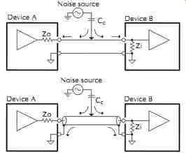
Figure 10. Capacitive noise coupling.
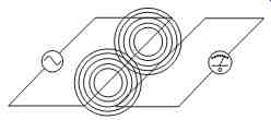
Figure 11. Inductive coupling between wires.
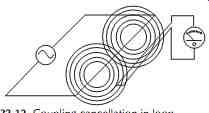
Figure 12. Coupling cancellation in loop.
Magnetic fields become weaker rapidly as distance from the source increases, usually as the square of the distance. Therefore, cancellation depends critically on the two conductors being at precisely the same distance from the magnetic field source. Twisting essentially places each conductor at the same average distance from the source. So-called star quad cable uses four conductors with those opposing each other connected in parallel at each cable end. The effective magnetic center for each of these pairs is their center line and the two sets of pairs now have coincident center lines reducing the loop area to zero. Star quad cable has approximately 100 times (40 dB) better immunity to power-frequency magnetic fields than standard twisted pair. The shield of a coaxial cable also has an average location coincident with the center conductor. These construction techniques are widely used to reduce susceptibility of balanced signal cables to magnetic fields. In general, a smaller physical area inside the loop results in less magnetic radiation as well as less magnetic induction.
Another way to reduce magnetic induction effects is shown in FIG. 13. If two conductors are oriented at a 90° (right) angle, the second doesn't cut the magnetic lines produced by the first and will have zero induced voltage. Therefore, cables crossing at right angles have minimum coupling and those running parallel have maximum coupling. The same principles also apply to circuit board traces and internal wiring of electronic equipment.
Magnetic circuits are similar to electric circuits.
Magnetic lines of force always follow a closed path or circuit, from one magnetic pole to the opposite pole, always following the path of least resistance or highest conductivity. The magnetic equivalent of electric current and conductivity are flux density and permeability. High-permeability materials have the ability to concentrate the magnetic force lines or flux. The permeability of air and other nonmagnetic materials such as aluminum, plastic, or wood is 1.00. The permeability of common ferromagnetic materials is about 400 for machine steel, up to 7000 for common 4% silicon trans former steel, and up to 100,000 for special nickel alloys.
The permeability of magnetic materials varies with flux density. When magnetic fields become very intense, the material can become saturated, essentially losing its ability to offer an easy path for any additional flux lines.
Higher permeability materials also tend to saturate at a lower flux density and to permanently lose their magnetic properties if mechanically stressed.
The basic strategy in magnetic shielding is to give the flux lines a much easier path to divert them around a sensitive conductor, circuit, or device. In general, this means that the shield must be a complete enclosure with a high magnetic permeability. The choice of the most effective shielding material depends on frequency. At low frequencies, below say 100 kHz, high-permeability magnetic materials are most effective. We can calculate how effective a conduit or cable shield will be at low frequencies:
...where, SE is shielding effect in dB, µ is permeability of shield material, t and d are the thickness and diameter (in the same units) of the conduit or shield.
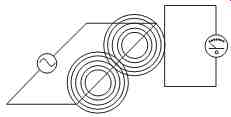
Figure 13. Zero coupling at right angles.
Thus, standard 1 inch EMT, made of mild steel with a low-frequency permeability of 300, will provide about 24 dB of magnetic shielding at low frequencies, but this will diminish to zero around 100 kHz. Fortunately, only low-frequency magnetic fields are generally a problem.
In severe cases, nesting one magnetic shield inside another may be necessary.
Typical copper braid or aluminum foil cable shielding has little effect on magnetic fields at audio frequencies. If a shield is grounded at both ends, it behaves somewhat like a shorted turn to shield the inner conductors from magnetic fields.
Depending on the external impedance between the grounded ends of a cable shield, it may begin to become effective against magnetic fields somewhere in the 10 kHz to 100 kHz range. Box shields of aluminum or copper are widely used to enclose RF circuits because they impede magnetic fields through this eddy current action and are excellent shielding for electric fields as well. There is an excellent explanation of this high-frequency shielding in reference 9. However, copper or aluminum shielding is rarely an effective way to prevent noise coupling from audio-frequency magnetic fields.
__4 Grounding
Historically, grounding became necessary for protection from lightning strokes and industrially-generated static electricity--i.e., belts in a flour mill. As utility power systems developed, grounding became standard practice to protect people and equipment. As electronics developed, the common return paths of various circuits were referred to as ground, regardless of whether or not they were eventually connected to earth. Thus, the very term ground has become vague, ambiguous, and often fanciful. Broadly, the purpose of grounding is to electrically interconnect conductive objects, such as equipment, in order to minimize voltage differences between them. An excellent general definition is that a ground is simply a return path for current, which will always return to its source. The path may be intentional or accidental-electrons don't care and don't read schematics!
Grounding-related noise can be the most serious problem in any audio system. Common symptoms include hum, buzz, pops, clicks, and other noises.
Because equipment manufacturers so often try to explain away these problems with the nebulous term bad grounding, most system installers and technicians feel that the entire subject is an incomprehensible black art. Adding to the confusion are contradictory rules proposed by various experts. Ironically, most universities teach very little about the real-world aspects of grounding. Graduates take with them the grounding fantasy that all grounds are equipotential-that is, have the same voltage. The fantasy certainly allows them to avoid complicated real-world interpretation of all those ground symbols on a schematic diagram, but the same fantasy can lead to noise disaster in their audio equipment and system designs.
Grounding has several important purposes and most often a single ground circuit serves, intentionally or accidentally, more than one purpose. We must under stand how these ground circuits work and how noise can couple into signal circuits if we expect to control or eliminate noise in audio systems.
__4.1 Earth Grounding
An earth ground is one actually connected to the earth via a low-impedance path. In general, earth grounds are necessary only to protect people from lightning. Before modern standards such as the National Electrical Code (NEC or just Code) were developed, lightning that struck a power line was often effectively routed directly into buildings, starting a fire or killing someone. Lightning strikes are the discharge of giant capacitors formed by the earth and clouds. Strikes involve millions of volts and tens of thousands of amperes, producing brief bursts of incredible power in the form of heat, light, and electromagnetic fields. Electrically, lightning is a high-frequency event, with most of its energy concentrated in frequencies over 300 kHz! That's why, as we discussed in Section 2.4, wiring to ground rods should be as short and free of sharp bends as possible.
The most destructive effects of a strike can be avoided by simply giving the current an easy, low-impedance path to earth before it enters a building. Because over head power lines are frequent targets of lightning, virtually all modern electric power is distributed on lines having one conductor that is connected to earth ground frequently along its length.
FIG. 14 shows how ac power is supplied through a three-wire split single-phase service to outlets on a typical 120 Vac branch circuit in a building. One of the service wires, which is often uninsulated, is the grounded neutral conductor. Note that both the white neutral and the green safety ground wires of each branch circuit are tied or bonded to each other and an earth ground rod (or its equivalent grounding electrode system) at the service entrance as required by Code.
This earth ground, along with those at neighboring buildings and at the utility poles, provide the easy paths for lightning to reach earth.
Telephone, CATV, and satellite TV cables are also required to divert or arrest lightning energy before it enters a building. The telco-supplied gray box or NIU provides this protection for phone lines as x grounding blocks do for CATV and satellite dishes. NEC Articles 800, 810, and 820 describe requirements for telephone, satellite/TV antennas, and CATV, respectively. All protective ground connections should be made to the same ground rod used for the utility power, if the ground wire is 20 ft or less in length. If longer, separate ground rods must be used, and they must be bonded to the main utility power grounding electrode with a #6 AWG wire.
Otherwise, because of considerable soil resistance between separate ground rods, thousands of volts could exist between them when lightning events occur or downed power lines energize the signal lines.
Without the bond such events could seriously damage a computer modem, for example, that straddles a computer grounded to one rod via its power cord and a telephone line protectively grounded to another.
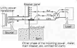
Figure 14. Simplified residential ac power from feeder to outlet. Other phase
of the incoming power , meter, main breaker, etc. omitted for clarity.
__4.2 Fault or Safety Grounding
Any ac line powered device having conductive exposed parts (which includes signal connectors) can become a shock or electrocution hazard if it develops certain internal defects. Insulation is used in power trans formers, switches, motors, and other internal parts to keep the electricity where it belongs. But, for various reasons, the insulation may fail and effectively connect live power to exposed metal. This kind of defect is called a fault. A washing machine, for example, could electrocute someone who happened to touch the machine and a water faucet (assumed grounded via buried metal pipes) at the same time.
NEC requires that 120 Vac power distribution in homes and buildings use a three-wire system as shown in FIG. 15. To prevent electrocution, most devices have a third wire connecting exposed metal to the safety ground pin of these outlets. The outlet safety ground is routed, through either the green wire or metallic conduit, to the neutral conductor and earth ground at the main breaker panel. The connection to neutral allows high fault current to flow, quickly tripping the circuit breaker, while the earth ground connection minimizes any voltage that might exist between equipment and other earth-grounded objects, such as water pipes during the fault event. Power engineers refer to voltage differences created by these fault events as step or touch potentials. The neutral (white) and line (black) wires are part of the normal load circuit that connects the voltage source to the load. The green wire or conduit is intended to carry fault currents only.
NEC also requires safety grounding of wiring race ways and equipment cabinets, including rack cabinets Per Article 250-95, safety grounding wires, which may be bare or insulated, must have a minimum size of #14 copper for a 15 A or #12 copper for a 20 A branch circuit to assure rapid circuit breaker action. This grounding path must be bonded to the safety grounding system, not to building steel or a separate earth ground system! Separate earth grounds cannot provide safety grounding!! As shown in FIG. 16, soil resistance is far too high to guarantee tripping of a circuit breaker under fault conditions. With safety grounds in place potentially deadly equipment faults simply cause high currents from power line hot to safety ground, quickly tripping circuit breakers and removing power from those branch circuits. Safety grounding in many residential and commercial buildings is provided through metal conduit, metallic J-boxes, and saddle-grounded or SG outlets. Technical or isolated grounding will be discussed in Section 7.
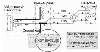
Figure 15. Fault protection is provided by safety ground to neutral bond. Utility
power transformer; Breaker panel; Ground rod; Short Earth; Defective equipment;
Fault currents range from 100 A to 1000 A; Trip times range from under 10 ms
to 2.5 s
When trying to track down and correct system noise problems, it easy to assume that power outlets are wired correctly. Low-cost outlet testers, which generally cost less than $10.00, will find dangerous problems such as hot-neutral or hot-ground reversals and open connections. Because they check for correct voltages between the pins, and both neutral and ground are normally a 0 V, they cannot detect a neutral-ground reversal. This insidious wiring error can create nightmarish noise problems in an audio system. Finding the error by visual inspection of outlets is one possibility, but this could get labor intensive if the number of outlets is large. For large systems, and even those that can't be powered down, a sensitive, noncontact, clamp-on current probe can help identify the forks in the road when trouble shooting.14 Code requires that neutral and safety ground be bonded only at the power service disconnecting means that is generally at the main breaker panel.
Serious system noise problems can also occur when an extraneous neutral-to-ground connection exists else where in the building wiring. A special test procedure can be used to determine this condition. NEVER, NEVER use devices such as three-prong-to two-prong ac plug adapters--a.k.a. ground lifters-to solve a noise problem! Such an adapter is intended to provide a safety ground (via the cover plate screw to a grounded saddle outlet and J-box) in cases where three-prong plugs must be connected to two-prong receptacles in pre-1960 buildings, FIG. 17.
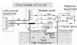
Figure 16. Fault protection is not provided by an earth ground connection!
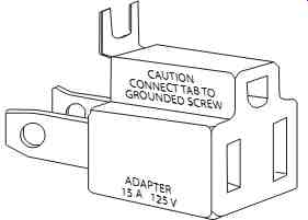
Figure 17. This is intended to provide a safety ground.
Consider two devices with grounding ac plugs that are connected by a signal cable. One device has a ground lifter on its plug and the other doesn't. If a fault occurs in the lifted device, the fault current flows through the signal cable to get to the grounded device.
It's very likely that the cable will melt and catch fire!
Also consider that consumer audio and video equipment is responsible for about ten electrocutions every year in the United States. In a typical year, this equipment causes some 2000 residential fires that result in 100 civilian injuries, 20 deaths, and over $30 million in property losses.
Some small appliances, power tools, and consumer electronics are supplied with two-prong (ungrounded) ac plugs. Sometimes called double insulated, these devices are specially designed to meet strict UL and other requirements to remain safe even if one of their two insulation systems fails. Often there is a one-shot thermal cutoff switch inside the power transformer or motor windings to prevent overheating and subsequent insulation breakdown. Only devices that carry a UL-listed label and originally supplied with ungrounded ac plugs should ever be operated without safety grounding. Devices originally supplied with grounding three-prong plugs must always be operated with the safety ground properly connected!
Interconnect cables can carry lethal voltages throughout a system if just one ground lifted device fails.
__4.3 Signal Grounding and EMC
EMC stands for electromagnetic compatibility, which is a field concerned with interference from electronic devices and their susceptibility to the interference created by other devices. As the world becomes increasingly wireless and digital, the general electromagnetic environment is becoming increasingly hostile. Engineers working in other disciplines, most notably information technology or IT-where signal/data frequencies are very high and narrowband-tend to minimize our difficulties in making audio systems robust against hostile electrical environments. In fact, high-quality audio systems are unique among electronic systems in two ways:
1. The signals cover a very broad, nearly 5 decade, range of frequencies.
2. The signals can require a very wide, currently over 120 dB, dynamic range.
Adding to the difficulty is the fact that ac power frequencies and their harmonics also fall within the system's working frequency range. As you might suspect, grounding plays a pivotal role in controlling both emissions and susceptibility in both electronic devices and systems. In general, the same principles and techniques that reduce emissions will also reduce susceptibility. Grounding schemes generally fall into one of three categories:
1. Single point or star grounding.
2. Multipoint or mesh grounding.
3. Frequency selective transitional or hybrid grounding.
At frequencies below about 1 MHz (which includes audio), virtually all experts agree that star grounding works best because system wiring is electrically short compared to the wavelengths involved. At these low frequencies, the dominant noise coupling problems arise from the simple lumped parameter behavior of wiring and electronic components. This includes the resistance and inductance of wires, the noise currents resulting from capacitances between utility power and system grounds, and magnetic and capacitive coupling effects.
On the other hand, at higher frequencies, system wiring can become electrically long and transmission line effects, such as standing waves and resonances, become the dominant problems. For example, because a 25 ft (7.5 m) audio cable is a quarter wavelength long at 10 MHz, it becomes an antenna. At frequencies of 100 MHz or higher, even a 12 in (30 cm) wire can no longer be considered low impedance path. To be effective at these frequencies, therefore, grounding schemes must emulate a flat metal sheet having extremely low inductance called a ground plane. In practice, this can usually only be approximated with a multipoint ground system using wires. The wire lengths between points must remain well under a quarter-wavelength so, as frequency increases, larger numbers of increasingly shorter wires must be used to create the mesh. Ultimately, only a real ground plane can produce low-impedance ground connections at very high frequencies. Even a ground plane is not a perfect or equipotential--i.e., zero volts at all points-ground.
Because it has finite resistance, significant voltage differences can be developed between connection points to it.
Therefore, it should come as no surprise that IT and RF engineers prefer mesh grounding techniques while audio engineers prefer star grounding techniques.
At power and audio frequencies, a so-called ground loop allows noise and signal currents to mix in a common wire. Single-point grounding avoids this by steering signal currents and noise currents in independent paths. But at ultrasonic and radio frequencies, noise currents tend to bypass wires because they look like inductors and tend to flow instead in unintended paths consisting of parasitic capacitances. This makes star grounding essentially useless in controlling high-frequency interference in practical systems. Mesh grounding does a better job of controlling high-frequency interference, but since many ground loops are formed, low-frequency noise can easily contaminate signals. For audio systems, sometimes even inside audio equipment, there is clearly a conflict.
This conflict can be resolved by the hybrid grounding scheme. Capacitors can be used to create multiple high-frequency ground connections while allowing audio-frequency currents to take a path determined by the directly wired connection. Thus, the ground system behaves as a star system at low frequencies and a mesh system at high frequencies.
This technique of combining ground plane and star grounding is quite practical at the physical dimensions of a circuit board or an entire piece of equipment. At the system level the same conflict exists regarding grounding of audio cable shields. Ideally, at low frequencies, a shield should be grounded at one end only, but for maximum immunity to RF interference it should be grounded at both ends (and even intermediate points, if possible).
This situation can be resolved by grounding one end directly and the other end through a small capacitor.
The shield grounding issue will be discussed further in Section 5.2.
__4.4 Grounding and System Noise
Most real-world systems consist of at least two devices that are powered by utility ac power. These power line connections unavoidably cause significant currents to flow in ground conductors and signal interconnect cables throughout a system. Properly wired, fully Code-compliant premises ac wiring generates small ground voltage differences and leakage currents. They are harmless from a safety viewpoint but potentiality disastrous from a system noise viewpoint. Some engineers have a strong urge to reduce these unwanted voltage differences by shorting them out with a large conductor. The results are most often disappointing. Other engineers think that system noise can be improved experimentally by simply finding a better or quieter ground. They hold a fanciful notion that noise current can somehow be skillfully directed to an earth ground, where it will disappear forever! In reality, since the earth has resistance just like any other conductor, earth ground connections are not at zero volts with respect to each other or any other mystical or absolute reference point.
__4.4.1 Power Line Noise
The power line normally consists of a broad spectrum of harmonics and noise in addition to the pure 60 Hz sine wave voltage. The noise is created by power supplies in electronic equipment, fluorescent lights, light dimmers, and intermittent or sparking loads such as switches, relays, or brush-type motors (i.e., blenders, shavers, etc.). FIG. 19 shows how sudden changes in load current, zero to full in about a microsecond for a triac light dimmer in this case, generate bursts of high-frequency noise on the power line 120 times per second. Even an ordinary light switch will briefly arc internally as it is switched off and its contacts open, generating a single similar burst. This noise contains significant energy to at least 1 MHz that is launched into the power wiring. The wiring behaves like a complex set of mis-terminated transmission lines gone berserk, causing the energy to reflect back and forth throughout the premises wiring until it is eventually absorbed or radiated. Power line noise can couple into signal paths in several ways, usually depending on whether the equipment uses two-prong or three-prong (grounding) ac power connections.
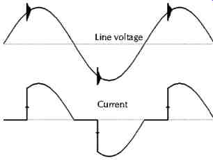
Figure 19. Light dimmer noise.
__4.4.2 Parasitic Capacitances and Leakage Current Noise
In every ac-powered device, parasitic capacitances (never shown in schematic diagrams!) always exist between the power line and the internal circuit ground and/or chassis because of the unavoidable interwinding capacitances of power transformers and other line connected components. Especially if the device contains anything digital, there may also be intentional capacitances in the form of power line interference filters.
These capacitances cause small but significant 60 Hz leakage currents to flow between power line and chassis or circuit ground in each device. Because the coupling is capacitive, current flow increases at higher noise frequencies. FIG. 20 shows the frequency spectrum of current flow in 3 nF of capacitance connected between line and safety ground at an ac outlet in a typical office.
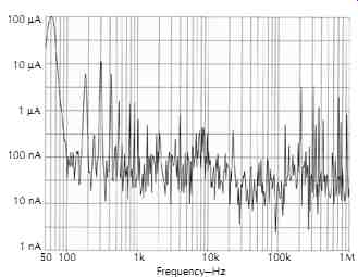
Figure 20. Typical leakage current from line to safety ground coupled via
3000 pF capacitance into a 75-ohm spectrum analyzer input.
This tiny current, although it poses no shock hazard, causes hum, buzz, pops, clicks, and other symptoms when it couples into the audio signal path. This capacitive coupling favors higher frequencies, making buzz a more common symptom than pure hum. We must accept noisy leakage currents as a fact of life.
__4.4.3 Parasitic Transformers and Inter-Outlet Ground Voltage Noise
Substantial voltages are magnetically induced in premises safety ground wiring when load current flows in the circuit conductors as shown in FIG. 21. The magnetic fields that surround the line and neutral conductors, which carry load current, magnetically induce a small voltage over the length of the safety ground conductor, effectively forming a parasitic transformer. The closer the safety ground conductor is to either the line or neutral conductor, the higher the induced voltage.
Because, at any instant in time, line and neutral currents are equal but flow in opposite directions, there is a plane of zero magnetic field exactly midway between the line and neutral conductors as shown in FIG. 22. There fore, Romex and similar bonded cables generally generate significantly lower induced voltages than individual wires in conduit, where the relative positioning of the wires is uncontrolled.
The voltage induced in any transformer is directly proportional to the rate of change of load current in the circuit. With an ordinary phase-control light dimmer the peak voltages induced can become quite high. When the dimmer triggers current on 120 times per second, it switches on very quickly (a few microseconds) as shown in FIG. 23. Since the magnetic induction into safety ground favors high frequencies, noise coupling problems in a system will likely become most evident when a light dimmer is involved. The problems are usually worst at about half-brightness setting of the dimmer.
This parasitic transformer action generates small ground voltage differences, generally under 1 V, between ac outlets. The voltage differences tend to be higher between two outlets on different branch circuits, and higher still if a device on the branch circuit is also connected to a remote or alien ground such as a CATV feed, satellite dish, or an interbuilding tie line. We must accept interoutlet ground noise voltage as a fact of life.
__4.4.4 Ground Loops
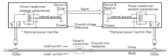
Figure 21. Voltage difference is magnetically induced over length of safety-ground
premises wiring.
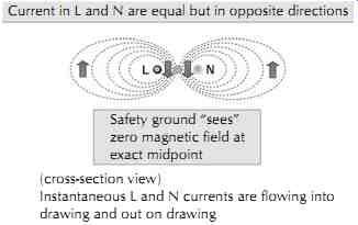
Figure 22. Magnetic fields surrounding line and neutral can induce voltage
into safety ground.
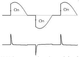
Figure 23. Lamp current (upper) versus induced voltage (lower) for phase-controlled
dimmer.

Figure 24. For grounded equipment, interconnect cables complete a wired loop.
For our purposes, a ground loop is formed when a signal cable connects two pieces of equipment whose connections to the power line or other equipment causes a power-line-derived current to flow in the signal cable.
The first, and usually worst, kind of ground loop occurs between grounded devices-those with three-prong ac plugs. Current flow in signal cables, as shown in FIG. 24, can easily reach 100 mA or more.
The second kind of ground loop occurs between floating devices-those with two-prong ac plugs. Each pair of capacitances CF (for EMI filter) and CP (for power transformer parasitic) in the schematic form a capacitive voltage divider between line and neutral, causing some fraction of 120 Vac to appear between chassis and ground. For UL-listed ungrounded equipment, this leakage current must be under 0.75 mA (0.5 mA for office equipment). This small current can cause an unpleasant, but harmless, tingling sensation as it flows through a person's body. More relevant is the fact that these noisy leakage currents will flow in any wire connecting such a floating device to safety ground, or connecting two floating devices to each other as shown in FIG. 25.