Equipment Test Reports
By Hirsch-Houck Laboratories
----------------
Akai GXC-725D Cassette Deck
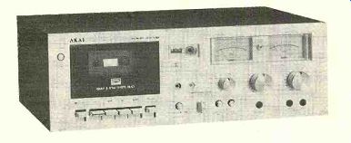
THE Akai GXC-725D is a moderately priced, front-loading, three-head cassette deck powered by a single electronically controlled d.c. motor. The transport mechanism is operated by the familiar row of levers below the cassette opening. Akai has arranged things so that the levers of the GXC-725D can be used in any sequence without going through STOP.
A single lever serves for both STOP and EJECT functions; the first pressure (even a very light one) stops the tape, and releasing it and pressing again opens the cassette door.
The cassette is loaded into retaining clips built into the hinged door. The door opens quietly, with a slow damped motion. It can be removed easily for cleaning or demagnetizing the heads. Most of the cassette can be seen through the window in the door, and it is back-lit so that one can always see how much tape remains to be played.
The recording and playback heads of the Akai GXC-725D, though electrically and magnetically separate, are built into the same housing, which fits through the hole in the edge of the cassette usually occupied by a combination record/playback head. Since the azimuths of the two head gaps are set precisely during manufacture, the GXC-725D does not require the alignment adjustments that are necessary with cassette recorders using physically separate recording and playback heads.
The cassette opening at the left of the panel is flanked by a pushbutton power switch and an index counter with reset button. The upper right portion of the panel is devoted to two large illuminated VU meters calibrated from -20 to +5 dB. Between them is a PEAK LEVEL light that flashes when brief signal peaks reach +7 dB.
------------
FREQUENCY IN HZ (CYCLES PER SECOND)
Below the meters are the two recording-level controls and a single playback-level control. Two indicator lights show when the machine is set for recording and when the Dolby system is turned on. Across the bottom of the panel, to the right of the transport controls, are pushbutton switches for MONITOR (delivering either the input source or the playback-output signals to the line outputs), DOLBY noise reduction, and the MPX FILTER that removes any 19-kHz pilot signal remaining in an FM stereo program, which might affect the operation of the Dolby circuits. There is a TAPE SELECTOR knob that simultaneously changes bias and recording and playback equalization for four basic tape formulations.
These are identified as LN (low noise), LH (low noise/high output), CrO2, and FeCr. A stereo headphone jack and two microphone jacks complete the front-panel features. The line input and output jacks are in the rear.
The instruction manual for the Akai GXC-725D contains complete performance specifications, which are too lengthy to repeat here. It also has a table listing the recommended settings of the TAPE SELECTOR for some twenty-five types of tape and shows the "reference" tape used for each of the switch settings to establish the recorder's performance specifications. The Akai GXC-725D is supplied in a vinyl-clad wooden cabinet finished in simulated walnut grain. It is approximately 17 1/2 inches wide, 111/4 inches deep, and 61/2 inches high and weighs about 15 pounds. Price: $399.50
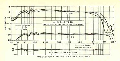
Laboratory Measurements. The playback frequency response was measured using TDK AC-331 and Nortronics AT200 test tapes for the "standard" 120-microsecond equalization, and Teac 116SP tape for the 70-microsecond equalization used with CrO2 and FeCr tapes. In both cases the response was within ±1 dB over the full range of the tape (31.5 to 10,000 Hz), most of the variation being at the lower frequencies.
The record-playback frequency response was measured for each of the tape-selector positions using the recommended reference tape or a close equivalent. For the LN and LH tapes we used TDK SD and Maxell UD XL in place of the specified Fuji FL and Max-
ell UD tapes. We also tried a Scotch Master tape with the LH setting. It is interesting to note that the CrO2 performance of the recorder is specified only with cobalt-treated ferric "chrome equivalents" such as TDK SA and Maxell UD-XL II, and no actual chromium-dioxide tapes are listed in the table. We tested the machine with the recommended TDK SA and also with BASF Chromdioxid Super. Finally, the FeCr position was checked with the recommended Sony Ferrichrome and the al ternate Scotch Classic.
Although there were of course differences in frequency response between the tapes, the similarities between them were striking. For example, the overall response of the TDK SD and Maxell UD-XL were virtually identical over most of the audio range. Most of the deviation from flatness was in the low-frequency "ripples" caused by the head geometry.
The overall response was within ±2 dB from 36 to 13,000 Hz with SD and from 34 to 15,000 Hz with UD-XL. Scotch Master (LH) had a mild high-frequency rise and a ±2-dB variation from 35 to 15,000 Hz. The TDK SA, used as a CrO2 tape, had a slightly stronger and extended high end, with a ±1.5-dB variation from 37 to 16,500 Hz. The BASF chrome tape had a more pronounced high-frequency rise above 4,000 Hz, giving it a ±2.5-dB variation from 35 to 18,500 Hz. The ferrichrome tapes gave the widest and flattest frequency response. Sony FeCr was within-171.5 dB from 36 to 19,000 Hz. Scotch Classic had a very smooth, linear response which sloped down ward slightly. It was within-1.-3 dB from 34 to 17,000 Hz. All these figures result from the tape/machine interface and do not necessarily reflect results that would be obtained with the same tapes on other machines.
All measurements were made at a -20-dB recording level. At a 0-dB level there was the expected rolloff of high-frequency response due to tape saturation. However, the loss of highs was much less than we normally measure on cassette decks, and the 0-dB curve remained above the -20-dB curve at all times instead of intersecting it, as usually happens with cassette recorders. This can undoubtedly be credited to the use of separate recording and playback heads whose gaps have been optimized for their particular functions.
The MPX FILTER cut off sharply above 13,000 Hz, reducing the recording response at 19,000 Hz by nearly 20 dB. The "tracking" of the Dolby circuits was excellent, with no more than a 2-dB difference between frequency-response curves run with and without the Dolby system at levels of -20 and -30 dB.
The GXC-725D uses a "double-Dolby" system with separate Dolby circuits for recording and playback functions, so that programs can be monitored from the tape as they are made and heard with the correct frequency response and noise levels.
For a 0-dB recording level, the required in put was 53 millivolts at the line jacks and 0.18 millivolt at the microphone jacks (the micro phone amplifier overloaded at 43 millivolts in put). The meters were calibrated so that the Dolby level of 200 nW/m registered +3 VU as marked. Their ballistic characteristics were exactly as specified for VU meters, so that they indicated 100 percent of steady-state readings when driven with 0.3-second tone bursts once per second. The PEAK LEVEL light began to glow at a +7-dB input.
The 1,000-Hz, 0-VU playback distortion was only 0.25 percent with TDK SD (LN), about 0.45 percent with Maxell UD-XL (LH) and TDK SA (CrO2) and 1 percent with Sony FeCr. All of these are well below the rated distortion levels for the recorder. The reference distortion level of 3 percent was reached at an input of +9 dB for LN, +10 dB for LH, +7 dB for CrO2, and +6 dB for FeCr.
The signal-to-noise ratio (S/N) was measured for each tape using unweighted measurements, I EC "A" weighting, CCIR weighting, and CCIR with Dolby noise reduction.
The differences between tapes were slight, with only about 2 dB separating Maxell UD XL from TDK SD in a weighted measurement with Dolby. Considering that the worst S/N we measured under those conditions was a very good 64.6 dB, it seems that "noisy" is hardly the proper adjective to use when discussing either the machine or any of the tapes! The noise level increased by 8.5 dB through the microphone inputs at maximum gain, but it was not obtrusive at normal gain settings.
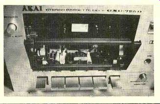
---------- View of the front-loading mechanism of the GXC-725D.
The cassette is loaded into clips on the door (which can be removed for head cleaning).
The tape transport worked smoothly and quietly. The unweighted rms flutter was only 0.09 percent. In fast forward or rewind the machine covered a C-60 cassette in 90 seconds. The PAUSE control started up the tape with a short but perceptible "fade in" that effectively eliminated any transient start-up speed variation. The headphone volume, even with 200-ohm phones, was very good.
Comment. Before making any measurements on the Akai GXC-725D, we connected it to a music system and put it into operation.
Its quality was immediately audible, to the extent that the later measurements did not surprise us at all. For example, we could record interstation FM tuner hiss and hear almost no difference between the input and playback signals from the recorder at a-10-dB recording level. Instead of the usual dulling of the highs, the major change in the playback quality was a slightly heavier low end, perhaps from the cyclic response variations below 100 Hz. In this test, the performance of the GXC-725D was closer to that of an open-reel tape deck than to other cassette decks (especially those in its price range).
We noticed that recording levels can be set up without placing the machine in the record mode (or even loading a cassette). The "head room" is considerably greater than is common in cassette recorders, so that it was safe to let the meters reach 0 dB regularly (which resulted in an occasional flash from the PEAK LEVEL light) when recording from FM or records. Of course, with live program material having greater dynamic range, one should keep the average levels a bit lower.
It was also apparent that the bias and equalization characteristics had been chosen to make the machine compatible with a variety of tapes, unlike some machines whose proper performance can be realized only with the specific type of tape for which they have been adjusted.
The GXC-725D lacks a few features found on some other deluxe cassette decks. For example, it has no "memory rewind" or provision for unattended recording with a timer switch. Its Dolby circuits cannot be used to decode an FM Dolby broadcast for listening only. Some of these features may be of importance to some people. To us, in view of what the GXC-725D did do and how well it did it, their absence was hardly noticed.
The Akai GXC-725D is a rare combination of an absolutely first-rate recorder (which sounds every bit as good as it measures) with a highly affordable price tag. This caliber of performance is available in a very few other cassette decks, all of which are much more expensive than the GXC-725D. It is also worth mentioning that this machine meets or surpassed--usually by a wide margin--every one of the ratings for which we were able to test, and it had not a single idiosyncrasy or "bug" that we could find. This might seem to be no more than one would expect from any well-made product, but it is nonetheless rare, and it contributed to our totally positive feeling about the GXC-725D.
++++++++++++++++
Acousti-phase Phase III+ Speaker
COMPARED with some widely sold and longer established speaker brands, the Acousti-phase name is perhaps not very well known to American audio hobbyists. This is partly because of the marketing policy of this relatively new, Vermont-based company, which limits its distribution to a single dealer in each geographic area. The Acousti-phase line includes models priced for budget systems and goes all the way to high-performance systems designed to compete with some of the most highly regarded brands.
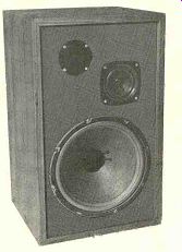
The Phase III+ which we tested is one of their top models. It is a conventional three way ported system in a walnut-veneer cabinet suitable for floor or shelf mounting. The brown foam-plastic grille is held in place by Velcro fasteners and is easily removable. A single 12-inch woofer is employed, and the enclosure's ducted port opens to the real.
Middle and high frequencies are handled by a 5-inch cone driver and a 1-inch Mylar dome tweeter. There are 12-db-per-octave crossover points at 900 and 5,000 Hz. Inset in the rear of the cabinet are the speaker terminals, a continuously variable tweeter-level control, and the reset button for a circuit breaker that protects the mid-range and high-frequency drivers against overload. Minimum and maximum continuous-power ratings are 8 and 100 watts. The speaker carries a 5-year unconditional and transferable warranty covering all defects not resulting from abuse, neglect, or accident, without charge for parts or labor.
The Acousti-phase Phase III+ is 25 inches high, 15 inches wide, and 13 1/2 inches deep. It weighs approximately 41 pounds. Suggested retail price: $289 in walnut veneer, $349.95 in solid-wood butcher block.
Laboratory Measurements. The reverberant-field response of the Acousti-phase Phase III+, with the tweeter-level control set at maximum, was within a 5-dB overall range up to about 5,000 Hz and rose smoothly at higher frequencies.
A close-miked measurement of the woofer response by itself showed a rising output with decreasing frequency down to the resonant frequency of about 80 Hz and then a steep fall-off at lower frequencies. This is a characteristic of ported systems, whose output goes to a null at some low frequency (in this case 37 Hz). The measured port radiation, corrected for the relative diameters of the port and the cone, was dominant below 45 Hz but was at a much lower level than the mid-range output of the woofer. When the curves were combined, the overall frequency response of the Phase III+ was ±3 dB from 60 to 5,000 Hz, with the output rising to a maximum of +8 dB at 12,000 Hz and falling rapidly below 60 Hz.
The tweeter-level control had a maximum range of about 10 dB and affected frequencies above 1,500 Hz. The tweeter dispersion was only fair, with a noticeable decrease in extreme top-end response at angles of 30 degrees or more off the central axis of the speaker. The system efficiency was quite high, with a sound-pressure level of 92 dB delivered at 1 meter from the grille when the system was driven by 1 watt (at 8 ohms) of random noise in the octave centered at 1,000 Hz.
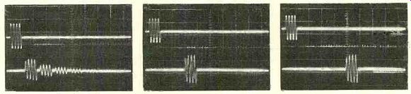
------------ Tone-burst response of the Phase III+ at (left to right)
100, 1,000, and 5,000 Hz. The upper trace is the input signal and the lower
trace the output of the speaker.
Since the bass distortion was measured only at the woofer cone, the test was valid only down to 45 Hz or so. At a nominal 1-watt input, the distortion was very low (under 0.5 percent) at 100 Hz and higher frequencies, in creasing smoothly to 4 percent at 50 Hz and 14 percent at 40 Hz. At a 10-watt drive level, the low-frequency distortion was approximately doubled, but it was not affected significantly above 100 Hz.
The impedance of the Phase III+ should be rated at 4 ohms, according to our measurements. That impedance value was found in the 30- to 40-Hz and 100- to 200-Hz ranges and above 1,500 Hz. There was a rise to 10 ohms at the lower measurement limit of 20 Hz (and it probably increased at still lower frequencies), a fairly sharp peak to 18 ohms at 75 Hz, and a broad plateau of 10 ohms at 600 Hz.
Tone-burst measurements at low and middle frequencies showed a fairly slow rise and fall time, covering one or two cycles at 100 and 1,000 Hz, with sustained ringing between bursts. The 5,000-Hz burst response was much better, with little inter-burst ringing.
Comment. The smooth frequency-response curve and slightly rising high-end response were good clues to how the Phase HI + would perform in our simulated live-vs.-recorded listening test. We have found that a measured rising high-frequency characteristic is generally associated with accurate reproduction of the highest audible octave in a normal listening room, and in this test the Phase III+ proved to be very good. The extreme top end, in fact, was outstanding, although on some "hot" program material a slight reduction in the tweeter level was desirable. Over all, the sound was smooth and free of the lower mid-range colorations heard from many speakers when their sound is compared directly with the original.
It is obvious that the Phase III+ was de signed to compete with some of the popular and expensive speakers having the so-called "West Coast" sound. It has clarity, high efficiency, smoothness, and an adequate bass response. It can be played very loud, if that is your preference, but it is equally at home with chamber music because of its smoothness and lack of coloration. We felt that the veneered finish of the cabinets left something to be desired in that it appeared to be more or less unfinished walnut. It was explained that there is an ultra-thin (and virtually invisible) protective coating over the veneer that shields it from stains-but prevents further finishing.
We operated the Phase III+ on the floor, on shelves, and on tilt stands that raised the speaker about a foot from the floor. In our room, the differences were slight, but it is al ways worth experimenting with speaker placement to obtain the best bass response in a particular room. Although, according to our measurements, the Phase III+ is not a speaker with a strong low bass, it certainly gave no audible hint of weakness in that area. Like wise, although its high-frequency dispersion properties were not outstanding in our test, in our listening room it gave no sign of audible beaming of highs. In general, it delivers a smooth, well-balanced sound without unnatural emphasis on any one frequency range.
Judging from several months of use tests, we would have to say that the total audible performance of the Phase III+ is considerably better than might be inferred from some of our measurements. As a matter of fact, these speakers "wear extremely well," and we enjoyed listening to them for extended periods-which certainly cannot be said for all speakers that come our way.
+++++++++++++++
Sound Concepts SD550 Time-delay System
TIME-DELAY devices have long been used to provide a more convincing illusion of reality in musical reproduction by simulating a concert-hall ambiance. In fact, years before stereo, acoustically driven spring devices were offered as "reverberation" accessories for home music systems. They usually im parted an unnatural "boinngg" sound to the program, however, and never met with much success in the marketplace. These crude devices should not, of course, be confused with the sophisticated (and expensive) mechanical delay devices made by AKG and others for professional use.
Several years ago, all-electronic time-delay devices began to appear on the professional market, but the first intended for consumer use was the Sound Concepts SD-50, a product of a small, newly formed company in Brook line, Massachusetts. It was based on the so called "bucket-brigade" principle, employing charge-coupled devices (CCD) to delay the program signal. The CCD is an integrated circuit containing hundreds of small capacitors separated by semiconductor switches which are opened or closed by signals from an external "clock" or timing oscillator. The signal waveform is sampled at regular intervals, and the first capacitor element is charged to the instantaneous amplitude of the signal. The next clock pulse causes the transfer of the stored voltage to the next capacitor, and the first element is then ready to sample the program level at the next moment of time. Every other clock pulse causes the stored signal to be shifted from one capacitor to the next and enters a new signal sample at the input to the CCD (the analogy to a fire-fighting "bucket brigade" is obvious).
Depending on the frequency of the clock pulse, the time it takes a signal to pass through the CCD array can be adjusted over a wide range. However, the clock frequency must be at least twice the highest program frequency, which sets a limit on the maximum delay. There is also a potential loss of high-frequency response and an increase in noise level as the delay time increases.
Time-delay units have also been made with digital circuits which first convert the analog program to a series of digital pulses. These, in turn, are passed through a series of digital memories or "shift registers," at a rate deter mined by the internal clock, before being re converted to analog form. Both types of delay systems (analog and digital) operate in much the same manner, although each has its ad vantages and disadvantages. One feature shared by all presently available time-delay units is their high price--$600 and up because of their circuit complexity, which far exceeds that of any other hi-fi component.
Sound Concepts is now producing their second-generation time-delay unit, the SD550.
Based on the same bucket-brigade principle used in the original SD-50, its control features have been extensively redesigned to increase its versatility, and it has been completely re packaged. The SD550 is intended to be connected between the preamplifier and power amplifier (it can be placed in a tape-monitor loop, but since it does not duplicate the tape-monitor switching this capability would be lost without the aid of an external tape-switch box). The incoming signal is connected to rear terminals marked FRONT IN; the adjacent FRONT OUT jacks go to the front-channel power amplifier. Normally, there is a direct connection internally between these jacks, so that the SD550 has no effect on the stereo pro gram going to the front speakers.
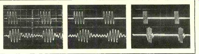
----------- Oscilloscope photos show the time relation between input (top) and delayed (bottom) signals. Delay times are (left to right) 5, 25, and 50 milliseconds. Photo at near right shows the effect of the reverberation circuits.
Within the SD550, each channel of the in coming signal passes through a 10,000-Hz low-pass filter, a pre-emphasis network, and a 2:1 compressor before reaching the CCD de lay circuits. After the delay, there is a 2:1 expansion (complementary to the compression) and a de-emphasis network. The purpose of these circuits is to reduce to inaudibility any noise added to the delayed program by the CCD. The delayed signals then go to the REAR OUT jacks.
There are separate time-delay circuits in each channel, both of them set by the same clock signal. A portion of each delayed output can also be fed back to the input of the opposite channel, where it is again delayed, and so on. This multiple delay technique adds reverberation effects to the sound. It is also possible to mix a selected fraction of the delayed rear signals with the otherwise unmodified front signals. Under certain circumstances this can enhance the overall effect, and it can also add delay and reverberation to the signal for stereo headphone listening or recording.
The rear-out signals go through another amplifier to a second pair of speakers located toward the rear of the room. Since the entire configuration then closely resembles a conventional four-channel playback arrangement, the SD-550 has been designed to inter face easily with a four-channel amplifier and speaker systems. It even has front-panel controls that switch the listening arrangement between four-channel and delay-enhanced stereo.
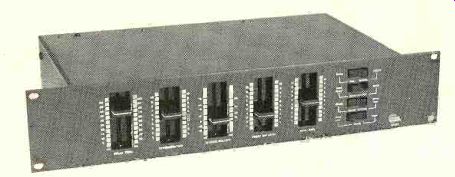
The front panel of the SD550 contains five vertical slider controls and four rocker switches. The DELAY TIME slider varies the internal clock frequency, and thus the delay time, between limits of 5 and 50 milliseconds (roughly corresponding to physical path-length differences of 5 to 50 feet). Next to it is the REVERBERATION control which varies the amount of cross-feed between the channels from 0 to 100 percent. The HI FREQ ROLLOFF is a specialized tone control affecting only the rear (delayed) signals. At its 0-dB setting, the high-frequency rolloff of the rear channels increases as the time delay is increased. This corresponds to the normal attenuation highs experienced as one moves back in a concert hall, where a greater portion of the high-frequency energy is absorbed by the surroundings. If one wants to retain the flattest possible response, the HI FREQ ROLLOFF control set to one of the "plus" positions boosts the rear-channel high-frequency response to compensate for the loss of highs at long delay times. The control is calibrated both in deci bels (+6 to-3) and in milliseconds (5 to 50) to correspond to the settings of the DELAY TIME control for which it compensates.
The remaining sliders are level controls.
The FRONT MIX LEVEL adjusts the fraction of the delayed signal that can be added to the front outputs. REAR LEVEL is a level control for the delayed outputs. Most of the rocker switches are used to convert the system for either four-channel or time-delay operation.
An INPUT switch feeds the time-delay circuits with either the front-channel program or with the rear-channel program from a quadraphonic source. The FRONT OUTPUT switch connects the front-channel input and output jacks directly or mixes the delayed program with the front outputs under the control of the FRONT MIX LEVEL slider. The REAR OUTPUT switch connects either the delayed signals or the rear channels of a quadraphonic preamplifier to the rear-output jacks. The DE LAY RANGE switch has positions for 50 (normal) and 100 milliseconds. However, the two stereo channels can be connected in tandem for very long delays, and they are driven by a summed signal (L + R) to give a monophonic delay of up to 100 milliseconds.
The Sound Concepts SD550 is 3 1/2 inches high by 9 inches deep and either 15 1/2 or 19 of inches wide, depending on whether the standard or rack-mount version is used. The entire unit is finished in black with white panel markings. It weighs 7 pounds and consumes 10 watts from the power line. It has no power switch, and the manufacturer suggests that it be left on continuously to eliminate any turn-on transients that might be fed to the rear speakers.
The gain of the unit is factory-set to 1, but it can be adjusted by screwdriver controls accessible in the rear. The input and output impedances are, respectively, 60,000 and 300 ohms. The rear-channel frequency response is rated at ±1 dB from 20 to 5,000 Hz with 5 milliseconds delay and a 0-dB high-frequency rolloff. With the rolloff set to match the delay, the response is down 3 dB at 8,000 Hz for all delay settings. The A-weighted output-noise level is at least 85 dB below 1 volt. The 1,000-Hz distortion at 1 volt is less than 1 percent and is almost entirely second harmonic.
The manual accompanying the SD550 is complete, written in a straightforward, "no-nonsense" manner, and we cannot take issue with anything in it. Price: $675 in either panel size.
Laboratory Measurements. Since the reasons for using time-delay enhancement are largely psychoacoustic, conventional measurements are not too informative. We did make frequency-response measurements through the rear delayed channels with various control settings. The manufacturer points out that the internal compander action will exaggerate any frequency-response variations measured with sine-wave signals. Taking that into account, our measurements nevertheless agreed closely with data supplied by Sound Concepts.
Using 0-dB rolloff, the response was flat within about 1 dB from 20 up to 6,000 Hz with a 5-millisecond delay, falling to-6 dB at 9,000 Hz (the equivalent of the-3-dB frequency in the equipment specifications, measured in a different manner). A 25-millisecond delay reduced the-6-dB frequency to 7,000 Hz; at 50 milliseconds it was 5,000 Hz. The HI FREQ ROLLOFF control could be used to re store the response at any setting of the DELAY control to approximately the 9,000-Hz value which was measured at minimum delay.
The distortion was, as claimed, virtually all second-harmonic, which is recognized as being least objectionable to the listener. At 1,000 Hz it varied from 0.28 percent at 0.1 volt to 0.79 percent at 1 volt and 1 percent at 3 volts. The distortion at 10,000 Hz was roughly the same. Noise levels could not be measured directly because the noise level of our active "A"-weighting network was greater than that in the SD550. We could see that the "noise" in its output was entirely com posed of clock pulses at a frequency which varied between approximately 30 and 300 kHz, depending on the setting of the delay control. Hum and random noise were substantially lower than-80 dB relative to 1 volt, although we could not establish the actual figure.
By driving the SD550 with a four-cycle tone burst of a 400-Hz signal, we were able to verify the accuracy of the DELAY time calibration and the effect of the REVERBERATION control.
The oscilloscope photos were taken with a time base (horizontal) of 10 milliseconds per division. The upper burst is the signal going into the unit and the lower one is the delayed output. Note that the actual time delay was very close to the control settings of 5,25, and 50 milliseconds. When maximum REVERBERATION is used, a series of successively weaker pulses can be seen in the rear output following the delayed pulse. Note that a similar series will appear in the other (undriven) channel at slightly different times. The short delay of 5 milliseconds was chosen for this so that several delayed signals could be seen in their correct relationship to the primary pulse. At the longer delays that would normally be used, the reverberant pulses could cover a much longer time span.
Comment. Measurements on a device such as the Sound Concepts SD550, though interesting to make, really do little more than confirm that it is operating properly. Any real judgment of its worth must be based purely on subjective impressions. We became aware of the advantages of time-delay systems when we first used the Sound Concepts SD-50 a couple of years ago, although the unit lacked a number of the refinements that have been incorporated into the SD550. Having lived with time-delay devices for some time, we had a pretty good idea of what problems to look for in any such system.
One difficulty is that the conditions which are optimum for one kind of music are not suitable for others, and none of them are correct for use with the human voice. A relatively long delay that sounds fine with music makes an announcer sound like he is talking from the other end of a long tunnel. This can be most disconcerting when listening to FM broadcasts! The seriousness of the effect seems to depend somewhat on the manner in which the reverberation system processes the multiply delayed signals. In no case should time-delay units be viewed as "echo" systems. If the controls are set so that everything sounds as if it were taking place in a cavern or a huge stadium, the unnaturalness of the effect soon becomes irritating.
Although the SD550 controls can be set to produce unnatural effects, its continuous adjustments make it easy to find the exactly correct delay, reverberation, and level that will yield satisfactorily natural ones. One advantage of the SD550 is the fact that it cannot be overloaded by any signal that is likely to exist between a preamplifier and a power amplifier and therefore needs no input-level controls.
And it is quiet-under no conditions could we hear any noise from the rear speakers.
Anyone who has not heard a time-delay system might wonder just what it does for the sound. In our experience, the ambiance contributed by a properly adjusted time-delay system does more to provide an illusion of reality in reproduced music than anything else we know of. Theoretically, good quadraphonic program material feeding a high-quality re producing system should do as well or better, but in practice this hardly ever happens. Furthermore, time delay imparts the same qualities to any stereo (or even mono) program in stead of being limited to special quadraphonic program material.
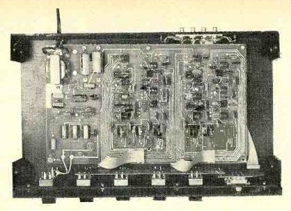
--------- Top view of the SD550 shows the complexity of the circuitry and the extensive use of integrated-circuit chips.
At its best, a time-delay system gives a sense of life and openness to the program, providing a spaciousness that simply cannot be realized naturally in a normal-size listening room. To achieve this, the channels must be balanced so that one does not hear the rear speakers as discrete sound sources, for this would completely destroy the illusion of reality. So, whatever one's choice of delay and reverberation conditions, the rear level should first be turned up until the rear speakers can just barely be heard, and then backed off until they cannot. If you doubt that the system is functioning, switch off the rear speakers while music is playing. The loss of reality is not at all subtle-it is so devastating that you will wonder how you ever got along without a time-delay system.
The Sound Concepts SD550 is not inexpensive, and when the cost of another stereo amplifier and a pair of speakers (which do not have to have the range of your main speakers) is included, a delay system can run to well over $1,000. Is it worth it? If you can afford it, yes! One thing is certain: you are not likely to be able to improve the sound of your present system, if it is already of reasonably high quality, by a comparable degree with any other expenditure of a lesser amount.
++++++++++++++++
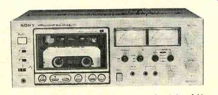
Sony EL-5 Elcaset Deck
WELL over a year ago, the elcaset format was announced to the audio world. The name is derived from L(arge) cassette, which is a fairly apt description of this new tape for mat. Developed by a consortium of Japanese manufacturers-JVC, Technics, Sony, and Teac-it is intended to bridge the gap between cassette and open-reel recording, to combine the convenience of the former with the performance of the latter. It also provides a few advantages peculiar to itself. At present, all the tapes are made by Sony, but each of the participating manufacturers (and some of their subsidiaries and affiliates) produces a line of elcaset decks that use them.
The elcaset cartridge is considerably larger than the familiar compact cassette, which it resembles in general configuration. Measuring roughly 6 x 4 x 44 inches, it is slightly larger than a standard eight-track tape cartridge. It contains standard-width 1/4-inch tape, which in the elcaset format is recorded in four parallel tracks, a pair of stereo tracks running in each direction of tape movement. In addition, there is provision for recording two narrow control tracks between the pairs of signal tracks; these might be used for controlling slide projectors or operating sophisticated signal processors in any machine designed to make use of them. At present, elcaset cartridges are available only in LC-60 and LC-90 lengths, or 30 and 45 minutes of program in each direction, respectively.
Unlike the cassette, with its 17/43-ips tape speed, the elcaset is designed to operate at 3 3/4 ips. The combination of nearly doubled tape-track width and doubled tape speed gives the elcaset format a powerful advantage over the standard cassette in terms of freedom from high-frequency tape saturation, which is probably the most serious technical limitation of the cassette medium. Another important...
-------------- 62 FREQUENCY IN Hz.
...feature of the elcaset is that the tape is with drawn from the housing during recording and playback, being passed over fixed heads in the machine as in an open-reel recorder. This makes possible almost any type of head con figuration. By contrast, the heads in the cassette format must be moved to contact the tape within the cassette, and a third (monitor) head can be used only with the exercise of technical and mechanical ingenuity.
The elcaset cartridge contains a number of coding notches and holes that give it a potential capability for almost totally automatic selection of operating parameters. For example, three types of elcaset tape have been announced (or are contemplated): a low-noise ferric-oxide tape (currently Sony SLH), Sony ferrichrome (FeCr), and a chromium-dioxide (CrO2) tape. Holes near one corner of the elcaset cartridge identify the tape type, and in a recorder equipped to use this information they could automatically select the required bias and equalization when the elcaset cartridge is inserted. Other "break-out" tabs, like those used on standard cassettes as a re cording lock-out, are used when a recording has been Dolbyized, and they could automatically switch a deck into Dolby mode if, again, the deck were designed to respond.
The elcaset can be made proof against accidental rerecording over a tape whose contents are to be preserved: instead of a break-out tab, a slide near one corner of the cartridge is moved to its "safety" position. If you want to record over the tape, the slide can easily be returned to its original position (the design makes accidental movement impossible). The internal tape hubs are locked in place when the cartridge is removed from the elcaset recorder, thus preventing the creation of tape slack during shipping or handling.
The Sony EL-5 is probably the most basic elcaset machine presently available. It has no automatic parameter-selection features and uses a two-head configuration that has a com bined record/playback head (as mentioned above, the elcaset format makes three-head tape transports perfectly practical, and Sony does make a more expensive model with that feature). Physically, the Sony EL-5 very much resembles a front-loading cassette deck. It is 17 inches wide, 63/4 inches high, and 123A inches deep; it weighs about 23 pounds.
The cartridge loads vertically behind a transparent hinged door at the left of the front pan el; an EJECT button opens the door. Below the door are light-touch pushbuttons that control the usual transport functions through solenoids: rewind, fast forward, play, record, and pause. Colored symbols above the buttons glow to show the operating mode of the machine, and a logic system allows the buttons to be operated in any sequence without dam age to the tape.
To the left of the elcaset door is a pushbutton POWER switch and two three-position levers that control TIMER and MEMORY functions. The TIMER switch can be used to start the deck in either the record or playback mode when there is an external clock timer in stalled in the power line. The MEMORY circuit can be set simply to stop the tape in rewind when the counter returns to 000 or to go into play automatically at that point. Below the MEMORY switch are the index counter and its reset button, plus a headphone jack for low-impedance phones.
Below the two large illuminated VU meters are four lever switches, two of which separately control the recording bias and equalization for the three available types of elcaset tape. A third switch controls the Dolby circuits, with an extra position for recording Dolby FM broadcasts. In the DOLBY FM mode the de-emphasis time constant of the tuner signal is changed to the required 25 microseconds and the recording level is set by a pair of controls in the rear of the machine so that the Dolby-level tone transmitted by some FM stations gives a 0-dB meter reading on the EL-5. The signal is recorded in its encoded form while the EL-5's outputs simultaneously provide a decoded version of the signal. The fourth switch turns on the MPX filter, which removes whatever 19-kHz pilot carrier might otherwise remain in the stereo FM signals being recorded.
At the right of the panel are two sets of con centric right-left recording-level controls for the LINE and MIC inputs, which can be mixed.
Across the bottom of the panel are the two microphone jacks, a stereo LINE input jack that replaces the normal LINE jacks on the rear apron when a plug is inserted, and a small knob that controls the playback level through the headphone jack.
The rear panel bears the LINE input and output jacks, a level adjustment for the line outputs, two FM CAL level controls, a socket for an optional remote-control accessory, and one switched and one unswitched accessory outlet. Suggested list price for the EL-5 is $630. Elcaset tapes range in price from $7 to $12, depending on type and length.
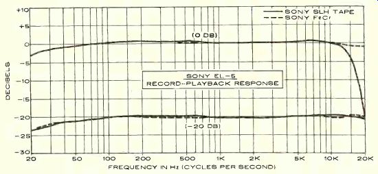
Laboratory Measurements. The Model EL-5 elcaset deck we tested came with a pre recorded demonstration tape and samples of several blank elcaset cartridges. Since there are no standard playback test tapes as yet for the elcaset, we made all our measurements by recording and playing back the same tape.
With the Sony SLH tape, the record-playback frequency response at a-20-dB level was within ±0.5 dB from 60 to 20,500 Hz. It was down 4 dB at 20 and 22,400 Hz. At a 0-dB recording level, the playback output dropped rapidly above 10,000 Hz owing to tape saturation. The superior high-frequency qualities of the ferrichrome tape were dramatically demonstrated by its frequency response, which was within ±0.5 dB from 60 to 24,000 Hz at-20 dB and down 4 dB at 20 and 26,200 Hz.
Even at 0 dB, the FeCr tape revealed little evidence of tape saturation, with a response within ±2 dB from 20 to 21,500 Hz. The MPX filter, which operates only during recording and had no effect up to 15,000 Hz, cut the 19-kHz response by at least 25 dB.
To reach a 0-dB recording level, a LINE in put of 56 millivolts (mV) or a MIC input of 0.145 mV was needed. The resulting playback level was about 0.65 volt. The microphone preamplifier overloaded at a 70-mV input. The superior tape headroom of the elcaset format was further demonstrated by a very low distortion (at a 0-dB recording level) of only 0.08 percent with SLH and 0.28 percent with FeCr tape, In fact, to reach a 3 percent distortion level on playback we had to record the tapes at +10 and +12 dB, respectively. With out Dolby, the unweighted signal-to-noise ratio (S/N) was 47.5 dB with SLH and 50 dB with FeCr. With the Dolby system switched in and using the CCIR weighting recommended by Dolby Laboratories, the S/N figures improved to 67.7 and 70.5 dB.
Through the microphone inputs, at maximum gain, the noise increased by 8.5 dB. The Dolby circuits tracked closely between the re cording and playback modes, changing the overall record-playback frequency response by no more than 1 dB at levels from -20 to -40 dB.
The unweighted rms wow and flutter was only 0.07 percent. An LC-60 elcaset was moved from end to end in the fast speeds in about 76 seconds. The VU meters were slower in their response than a true VU meter, reaching 65 to 70 percent of their steady-state readings on 0.3-second tone bursts. The headphone volume was adequate with 8-ohm phones but rather low with 200-ohm phones.
Comment. There can be no doubt that the elcaset, especially with the FeCr tape, is a medium that is technically superior to the compact cassette, especially with respect to high-frequency recording headroom. Operating at 33/4 ips, the elcaset matches the performance of some open-reel decks operating at 7 1/2 ips. Of course, much of the credit for this must go to the FeCr tape, which is not generally available for open-reel machines (nor are such machines, with the exception of one or two Sony models, equipped to use it).
Nevertheless, judged solely on its own merits, the elcaset, even in the form of the modestly priced EL-5, appears to be a no-compromise high-fidelity recording medium for the home recordist. Only the best cassette recorders can approach its overall performance, and then only when their recording levels are carefully monitored.
We found the Model EL-5 to be a very easy deck to use. The absence of a third head for monitoring caused us some concern at first, but we soon found that the entire recording process was so noncritical that there was little need to monitor while recording. The elcaset is as easy to handle as a regular cassette (per haps easier, because of its larger size). Presumably it could be spliced and edited like open-reel tape, although we would have misgivings about withdrawing any substantial amount of the tape from an elcaset housing.
We have given considerable thought to the place of the elcaset in the audio market. Our first reaction to its announcement was one of skepticism. After all, who needs a "better" cassette? But, having lived with the EL-5 for some time now, we appreciate how much of a "better cassette" it really is. The FeCr cartridge is really a full equivalent of 7 1/2-ips open-reel tape in terms of overall performance. In contrast to the handling clumsiness of open-reel tape, the elcaset offers all the convenience of use that has helped make the compact cassette so popular. Further, the elcaset recorder is closer in size and weight to a cassette deck than to an open-reel machine.
One should be aware that, for dubbing most phonograph records and FM broadcasts, the elcaset does not offer any quality advantage over the compact cassette. Only when the dynamic range of cassettes is inadequate or marginal (as in the case of most "live" recording) does the elcaset audibly demonstrate its superiority. There are no commercially recorded elcaset tapes on the market, and we would not expect any significant number to be produced.
The elcaset is strictly for the do-it-yourself tape enthusiast who has access to the finest recorded program material or to the real thing-live music. In respect to the big question-Which of the three formats is best for any individual's purposes?-the answer is obvious: it is a simple matter of weighing each format's pros and cons (including cost and available recording and playing time) against the requirements of the recordings you want to make.
ADC ZLM Phono Cartridge
SEVERAL major manufacturers are now producing stereo phono cartridges whose stylus shapes were derived from the special styli originally developed for playing CD-4 records. These stereo versions are not quite so extreme in their edge contours as the Shibata and similar designs, but like them they con tact a much longer portion of the groove wall than conventional elliptical or conical shapes do. The result is extended high-frequency response, reduced distortion (since the stylus shape is closer to that of the chisel-tipped cutting stylus that made the master disc), and reduced record wear because of the greater con tact area between the stylus and the record groove.
The latest of this new breed of cartridges is ADC's top-of-the-line ZLM, which features the company's "Aliptic" stylus. Its scanning radius, which traces the groove modulation, is only 0.2 mil, and its bearing radius, across the groove wall, is 1.5 mils. ADC makes the claim of "zero record wear" for the ZLM. They justify this by pointing out that the average record is played only about sixty times during its life, and microscopic examination of re cords played with the Aliptic stylus show no wear after seventy-five or more plays. Thus, ...
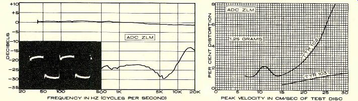
--------- In the graph at left, the upper curve represents the smoothed,
averaged frequency response of the cartridge's right and left channels; the
distance (calibrated in decibels) between it and the lower curve represents
the separation between the two channels. The inset oscilloscope photo shows
the cartridge's response to a recorded 1,000-Hz square wave (see text), which
indicates resonances and overall frequency response. At right is the cartridge's
response to the intermodulation-distortion (IM) and 10.8-kHz tone-burst test
bands of the TTR-102 and TTR-103 test records. These high velocities provide
a severe test of a phono cartridge's performance. The intermodulation-distortion
(IM) readings for any given cartridge can vary widely, depending on the particular
IM test record used. The actual distortion figure measured is not as important
as the maximum velocity the cartridge is able to track before a sudden and
radical increase in distortion takes place. There are very few commercial
phonograph discs that embody musical audio signals with recorded velocities
much higher than about 15 cm/sec. -----
... for all practical purposes, they feel, the ZLM cartridge will never wear out a record in home use.
The ADC ZLM is designed to track at forces between 0.5 and 1.25 grams. Its rated frequency response, when terminated in 47,000 ohms and 275 picofarads, is within ±1 dB from 10 to 20,000 Hz, or ±1.5 dB from 20 to 26,000 Hz. The rated output voltage is 1 millivolt per cm/sec of stylus velocity, and the nominal channel separation is 30 dB at 1,000 Hz and 20 dB at 10,000 Hz. Physically, the ZLM resembles the XLM series which formerly headed the ADC line (it is still there, just behind the ZLM).
Like the other ADC cartridges, the ZLM is an induced-magnet type with an easily replaceable stylus assembly. The nude diamond is mounted at the end of a tapered cantilever.
Each cartridge is supplied with its individually run response curve. It is packaged in a truncated conical plastic case somewhat resembling an Apollo spacecraft, together with a small screwdriver and a stylus cleaning brush.
Price: $135.
Laboratory Measurements. The ADC ZLM was tested in a tone arm with an equivalent mass of 16.5 grams, typical of today's better integrated record players. Initial tracking tests with several high-stress test records established that the 1.25-gram rated maximum tracking force was optimal for these discs, and all subsequent tests and listening were carried out with a 1.25-gram force. That was sufficient to enable the cartridge to track the 30-cm/sec, 1,000-Hz tones and the very high level 32-Hz tones on a couple of our test records. However, with the German Hi-Fi Institute record, the highest level of the 300-Hz test tones that could be played without obvious mistracking was the 60-micron level.
The measured vertical tracking angle was 20 degrees, the industry standard. The cartridge output, which was identical on both channels, was 2.95 millivolts at 3.54 cm/sec.
The square-wave response from the CBS STR112 record showed a single moderate overshoot, with very low-level ringing at about 40,000 Hz across the full width of the square wave. This is a property of the test record, not the cartridge, but it is rarely seen in the output of magnetic cartridges because of the rolloff of high frequencies caused by their coil inductance. Previously, we have seen this ringing principally in the output of moving-coil magnetic cartridges and nonmagnetic types; its presence in the output of the ZLM implies a frequency response extending far above the audio range.
We measured the frequency response with the CBS STRI00 record using a 250-picofarad capacitive load. The response was exception ally flat, with a slight downward slope as the frequency increased. Overall, the response was within ±1 dB over the full 40- to 20,000-Hz range of the test record. Channel separation averaged 20 to 25 dB through the mid-range, 15 to 18 dB at 10,000 Hz, and 13 dB at 20,000 Hz. The low-frequency resonance in the test arm was at 9 Hz with a 6-dB amplitude. Although most arms are slightly more massive than the one we used, we would expect the resonance to occur above 7 Hz in almost any arm.
Tracing distortion was measured with two Shure test records, the TTR102 (IM distortion) and the 'TTRI03 (high-frequency tracking of a 10.8-kHz tone-burst signal). The IM was a moderately low 1 to 2 percent up to about 18 cm/sec velocity, increasing to 8 percent at 27 cm/sec. The high-frequency distortion was very low, increasing smoothly from 0.7 percent at 15 cm/sec to 1.6 percent at 30 cm/sec. In this test the ZLM ranked with the best cartridges we have tested.
A subjective tracking test with Shure's "Audio Obstacle Course-Era III" essentially confirmed these measurements. The musical sections, whose highest levels frequently overtax the tracking abilities of even very good cartridges (musical bells, sibilants, and violin), were played easily by the ZLM at 1.25 grams. In particular, the very difficult sibilance test, which tends to sound "sand-papery" on its highest level when played by most cartridges, was reproduced flawlessly by the ZLM. On the other hand, the bass drum proved to be too much for the ZLM. There was a slight buzz on level 4 and a definite rattle on level 5.
Comment. ADC cartridges, including the ZLM, have a flat bottom that lies just above the plane of the record. This requires that the cartridge be exactly parallel to the record or the cartridge body will contact the record surface. Since the stylus protrudes only slightly from the bottom of the cartridge, it is not possible to operate the cartridge significantly above its rated maximum force, which would cause the stylus to retract within the protective body.
Aside from its test-record performance, we found the sound of the ADC ZLM to be absolutely first-rate on music records of all types.
High-velocity test records greatly exceed the maximum recorded levels one is likely to find on a music record, so that an inability to track a particular test band does not necessarily rule out the cartridge for critical music listening (most of the highly touted moving-coil cartridges do not do well on test records, but they are esteemed by critical listeners).
In particular, we listened on music for signs of low-frequency mistracking, since that seemed to be the weakest part of the ZLM's performance. Even with the drums on some of the Sheffield direct-to-disc recordings we heard no sign of distress from the cartridge.
And at high frequencies it was superb, with the effortless transparency that comes from low tracking distortion and a ruler-flat frequency response.
Also see: ADC ZLM cartridge
++++++++++++++
++++++++++++++
Also see:
NEW PRODUCTS: Roundup of the latest audio equipment and accessories
A BEGINNER'S GUIDE TO HI-FI---Selecting equipment intelligently is something anyone can do ROBERT N. GREENE
Technical Talk, Julian D. Hirsch
I Remember Mono--An Audiobiography
Source: Stereo Review (USA magazine)