EQUIPMENT TEST REPORTS, Hirsch-Houck Laboratory test results on the: Scott Model 830Z audio analyzer, B&O MMC 20CL phono cartridge, Yamaha CR-840 AM/FM stereo receiver, KEF Model 105 speaker system, and Soundcraftsmen SP4002 preamplifier
By Hirsch-Houck Laboratories
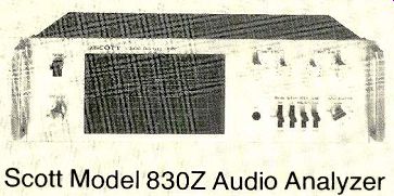
Scott Audio Analyzer
THE interest of many advanced audio hobbyists in the performance of their systems and components has led to the development of a number of test instruments specifically designed for home (that is, nonprofessional) applications. For example, in the heyday of quadraphonics audio oscilloscopes were available from several hi-fi manufacturers.
Their ability to display the directional distribution of four-channel programs (doubling as FM tuning and multipath indicators in most cases) made them interesting and informative tools for the technically oriented user, and they were styled to harmonize with other audio components.
Recently several smaller manufacturers have introduced inexpensive audio peak-level indicators using light-emitting diodes (see the test reports on the Uni-Sync and Audio Technology units in the October 1978 issue). however, a totally different level of sophistication is represented by the new Scott Model 830Z Audio Analyzer. This is a ten-band real-time spectrum analyzer with a built-in multi-frequency signal source that enables it to measure the frequency response of a component or a complete system (a small, wide-range microphone is included for acoustic frequency-response measurements).
The display of the Model 830Z is a grid of red LED's that are seen as short horizontal bars of light. There are ten vertical rows, one for each of the octave bands. Each vertical row contains eleven LED's corresponding to the signal amplitudes in that frequency band.
A three-position switch on the front panel selects the display range of the analyzer, which can be ±20, ±15, or ±10 dB (with the 0-dB reference level at the center of the scale). For these ranges, the level change corresponding to one vertical "division" is 4, 3, or 2 dB, respectively. Intermediate levels can also be read, since when two lights are on simultaneously the actual value is midway between them. The amplitude-scale calibrations appear to the left of the frequency scales, with the selected range indicated by an illuminated LED at the bottom of its scale.
The display, appearing against a black background with clearly visible white markings on the plastic screen, occupies almost half the front panel. To its left are the power switch and an OSC LEVEL knob that adjusts the amplitude of the test signal appearing at the rear terminals. Across the upper right of the panel are level controls for the microphone and line inputs. Each consists of a seven-position rotary switch (10 dB per step) and a continuously variable vernier adjustment.
Below the level controls are the mic jack and input selector (for mic, LINE, and CAL).
The line inputs can be either the left or right channel or their sum. The CAL position of the switch connects the test-oscillator signal to the analyzer input, giving a horizontal line of glowing LED's. When the LINE LEVEL switch is set to 0 dB, the CAL display is at the 0-dB mark (the center line).
Four lever switches complete the control lineup of the Model 830Z. The RANGE switch selects a display range of 20, 30, or 40 dB. In its FLAT center position the three-position WEIGHT switch causes the analyzer to have a uniform response to all frequencies in its range. The other two positions provide the standard IEC A or C weighting curves for acoustic or noise measurements. A MODE switch selects either ANALYZER or SPL modes.
In the latter, the spectrum-analyzer display is replaced by a single vertical scale display of the level of the total input signal. With the microphone input, the 0-dB SPL indication corresponds to the sound-pressure level (SPL) chosen by the MIC INPUT LEVEL switch (from 50 to 110 dB). The 40-dB amplitude scale provides SPL readings from 30 to 130 dB. A fourth two-position switch, LINE, selects either the HIGH or Low inputs at the rear of the instrument. They are electrically identical, but HIGH uses insulated speaker-type terminals for connection to an amplifier's speaker outputs and Low uses phono jacks for connection to tape-recorder or preamp outputs.
The inputs and outputs of the Model 830Z (except for the mic input) are in the rear of the unit. A 7-inch, 33 1/3-rpm record is supplied with the analyzer for record-player and pho no-preamplifier testing. It provides all the test tones normally generated by the Model 830Z except that they are RIAA equalized and appear simultaneously. The Model 830Z is 17 inches wide, 5 1/4 inches high, and 14 1/4 inches deep, and it weighs about 10 pounds. Price: $599. Rack-mounting adapters with handles are available for $24.
Laboratory Measurements. Our measurements of the Scott Model 830Z were limited to verifying its rated performance specifications. The center frequency of each filter was measured, and the frequency errors varied from 6.7 percent at 32 Hz to 0.9 percent at 16,000 Hz, well within the rated accuracy of ±20 percent. We checked the response at 32,1,000, and 16,000 Hz on all three amplitude scales. The largest error was 2 dB; typical errors near the center of the scale were about 1 dB or less.
The outputs of the oscillator section were measured on our Hewlett-Packard spectrum analyzer. The maximum level variation among the ten tones was 1 dB (rated ±1.2 dB). The sensitivity and display range of the LINE inputs was checked over the full range of the LEVEL switch. A 0-dB (center scale) indication could be obtained with inputs from 9 millivolts to 14.5 volts. The ±20-dB scale of the amplitude display extends the visible display range from 0.9 millivolt to 145 volts, more than enough for any dynamic range that will be encountered in a home music system.
---------------
HOW IT WORKS
At the heart of the Scott Model 830Z is a 16,000-Hz voltage-controlled oscillator whose frequency is successively halved to generate signals at 8,010.4,000, 2,000, 1.000, 500, 250, 125, 63, and 32 Hz as well. The square-wave output of each divider is filtered to approximate a sinusoidal shape. There are two more divisions of frequency, for use in the internal operation of the instrument. An 8-Hz component is fed back to the 16,000-Hz oscillator, frequency-modulating it to form a family of "warble-tone" signals in or der to avoid activating room resonances during acoustic measurements. And the intermediate 16-Hz signal operates a multiplexing circuit that successively connects each of the ten rest .Signals to the rear output terminals, covering the audio band at the rate of sixteen times per second.
THE input to the Model 830Z is fed in parallel to ten octave-wide bandpass filters whose center frequencies are the same as the ten test frequencies. The outputs of the filters are individually processed by logarithmic amplifiers and then detected. The ten detector outputs are switched by the same 16-Hz frequency that controls the sequence of test-tone outputs, so the frequencies of the output signals and the input filters are al ways synchronized.
---------------
The frequency response of the Model 830Z was checked in the flat, A-weighted, and C-weighted modes, and in each case it agreed very closely with the curves shown in the instruction manual. We did not check the response of the microphone (rated from 30 to 16,000 Hz ±3 dB), but the supplied calibration curve showed it to be well within those limits. Scott suggests that the microphone be gripped as far as possible from the actual element during acoustic measurements to pre vent any effect on the response from handling noise or reflections from the hand. One simple way to accomplish this would be to tape the mike to one end of a pencil, holding the pencil's other end during acoustic-response measurements.
Comment. Real-time spectrum analyzers, which display the amplitudes and frequencies of all components of a complex signal as they occur. are widely used in adjusting sound systems and equalizing auditoriums as well as in general acoustic analysis. As a rule, they are much too expensive and unnecessarily precise for casual home or hobby use. The Scott Model 830Z is the first such instrument we have seen that was specifically designed for home use.
When this analyzer is connected across the speaker outputs of an amplifier or receiver, it reveals in a dramatic and easily understood manner how the energy content of recorded music programs is distributed: most of the energy is in the middle of the audio spectrum, with little or none appearing at the lowest and highest frequencies. The LED's of the Scott 830Z respond fairly rapidly to signal transients (though not as fast as a good LED peak-level indicator), so the display is reason ably valid as an indicator of true maximum levels at different frequencies. There was an error of less than 1 dB for a 300-millisecond tone burst and about 4 dB for a 100-millisecond burst at 1,000 Hz. The display de cays slowly, taking I to 2 seconds to die away after the signal disappears, and it therefore gives a more or less continuous picture of the amplitude and frequency of the program.
The test record included with the analyzer is a convenient way to check the complete response of a phono system (the disc is RIAA equalized and gives a "flat" response through a correctly equalized preamplifier, subject only to the variations introduced by the phono cartridge). Scott also suggests using the Mod el 830Z to check the response of a tape recorder including the effect of bias and equalization adjustments. By recording the oscillator test signal on tape and playing it back into the analyzer, the overall frequency response can be seen at a glance. With the aid of the Model 830Z, it takes but a moment to trim the bias of a three-head cassette recorder for the flattest frequency response with any tape. Using the microphone, you can measure the response of your listening room and speakers, and if an octave-band equalizer is available, it can be used together with the spectrum analyzer to equalize the room and speakers in a fraction of the time that would be required for conventional point-by-point adjustments.
All of this technical capability has been available in the past, but at a cost many times that of the Scott Model 830Z. We found this novel instrument to be most useful-perhaps the most valuable test and analysis accessory a technically oriented audiophile could have.
In addition to its obvious value in making system adjustments and checks, it is a continuing audio education: watching the display while listening to different kinds of program material is most instructive.
+++++++++++++
B&O MMC 20CL phono cartridge
THE new MMC 20 series of stereo phono cartridges from Bang & Olufsen represents an evolutionary advance over the Danish manufacturer's preceding models (they describe it as a "new generation" of cartridges). Like earlier B&O cartridges, the MMC 20 series is based on the moving-iron principle, with a symmetrical X-shaped armature attached to the stylus cantilever at one end. As the armature of a cartridge is deflected in use by stylus movement, it varies the flux distribution from a powerful fixed magnet to the four pole pieces. Surrounding each pole piece is a coil of wire (there are 2,500 turns in each coil), and the rate of flux change induces a proportional voltage in the coils, which are connected in pairs to provide the two-channel stereo output.
Cartridges in the MMC 20 series are also very similar in general appearance to older-model B&O cartridges, but there are some major differences. For example, instead of the usual metal stylus cantilever (normally aluminum or beryllium), the MMC 20 cartridges have cantilevers that are each formed from a single sapphire crystal.
The choice of such an exotic material was by no means arbitrary. It was dictated by the need for the stiffest possible cantilever structure. Since no cantilever is perfectly rigid, there is inevitably some flexing as the stylus moves in the groove, and consequently some cantilever resonance, usually somewhere in the upper two audible octaves. This resonance must be carefully damped in order to achieve a reasonably flat frequency response in the audio band, and this damping can affect the transient response of the cartridge.
--------------
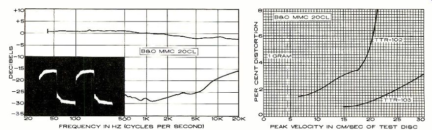
In the graph at left, the upper curve represents the smoothed, aver aged frequency response of the cartridge's right and left channels; the distance (calibrated in decibels) between it and the lower curve represents the separation between the two channels. The inset oscilloscope photo shows the cartridge's response to a recorded 1,000-Hz square wave (see text), which indicates resonances and overall frequency response. At right is the cartridge's response to the intermodulation-distortion (IM) and 10.8-kHz tone-burst test bands of the TTR-102 and TTR-103 test records. These high velocities provide a severe test of a phono cartridge's performance. The intermodulation-distortion (IM) readings for any given cartridge can vary widely, depending on the particular IM test record used. The actual distortion figure measured is not as important as the maximum velocity the cartridge is able to track before a sudden and radical increase in distortion takes place. There are very few commercial phonograph discs that embody musical audio signals with average velocities much higher than about 15 cm/sec.
------
Beryllium is relatively stiff compared with aluminum, the most common material used for stylus cantilevers, so a beryllium cantilever shifts the resonant frequency higher in the audio range, where its effects are less apparent. According to B&O, single-crystal sapphire is 40 percent stiffer than beryllium and more than five times as stiff as aluminum. Moreover, its resonance is above 20,000 Hz, making a flat response in the audio range possible without large amounts of pivot damping. B&O also points out that the velocity of sound in sapphire is twice that in aluminum, thus reducing possible phase distortions at high frequencies as the vibrations propagate up the cantilever from the stylus to the generating armature.
The MMC 20 cartridges have tiny, nude-diamond styli bonded to the tips of their sapphire cantilevers. Depending on the particular model, the stylus may have a spherical, elliptical, or "line-contact" shape. The MMC 20CL, the model we tested, has a line-contact stylus, which tracks the groove more accurately and distributes the vertical tracking force over a larger area of the groove walls. The stylus is not user-replaceable.
Final testing of B&O MMC 20 cartridges is done by a sophisticated computer-controlled test system developed by B&O engineers. This thoroughly evaluates a cartridge's performance much more rapidly and accurately than would be possible with conventional means. An individual calibration card printed out and packed with each cartridge shows its output voltage, channel balance, midrange channel separation, and output at 16,000 Hz compared with the 1,000-Hz level. In addition, the top-of-the-line MMC 20CL comes with an individually calibrated frequency-response chart.
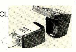
The MMC 20CL is a very small, lightweight cartridge. It is designed to plug directly into the tone arms of B&O record players so as to minimize the total effective arm mass, but included with each cartridge is an adapter for installing it in any conventional tone arm with half-inch-spaced mounting centers (the adapter is shown separated from the cartridge in the photo on page 40). MMC 20CL cartridges also come with a stylus-force gauge, a stylus-cleaning brush, and a small screwdriver. Price: $150.
Laboratory Measurements. We installed the B&O MMC 20CL in the tone arm of a Denon DP-2500 record player. The cartridge is designed to track at I gram, and that force was used throughout our tests. The preliminary specifications and information accompanying our early production-sample cartridge did not mention a recommended load capacitance other than to indicate that the cartridge windings have a low inductance and are thus not critically dependent on any specific load capacitance. We used a typical cartridge load of 47,000 ohms in parallel with 220 picofarads (pF), and we later checked the effect of other capacitance values on the frequency response (it was very slight).
The frequency response of the MMC 20CL was notably smooth and linear (a characteristic of previous B&O cartridges we have test ed). It sloped downward very slightly with in creasing frequency but never deviated more than a fraction of a decibel from a straight line response. With the CBS STR 100 test record, the output between 5,000 and 20,000 Hz was about 3 dB lower than at 500 Hz. With a JVC TRS-1007 record, the total variation was only-±1 dB from 1,000 to 20,000 Hz. The channel separation averaged about 28 dB at 1,000 Hz, 15 to 20 dB at 10,000 Hz, and about 15 dB at 20,000 Hz.
The frequency response was affected only slightly by a very large change of load capacitance: increasing the capacitance from 70 to 420 pF raised the output by about 1.5 dB maximum in the 5,000-to 20,000-Hz range. With the higher capacitance value, the overall response with the CBS record was a very good ±1.5 dB from 40 to 20,000 Hz. A square-wave test (with the CBS STR 112 record) showed no overshoot, a very rapid rise time on the leading edge, and a somewhat unusual rounded top on the square wave. The output of the cartridge was about 3.1 millivolts per channel at a recorded velocity of 3.54 cm/sec, and the channel levels were matched within 0.4 dB. The vertical stylus angle was 22 degrees.
Tracking tests with several high-velocity test records showed the MMC 20CL to be satisfactory in this respect. With the Shure "Audio Obstacle Course" records there was usually some indication of incipient mistracking, such as a hardness or roughness in the sound, on level four. On level five of most sections the mistracking was unmistakable. Note, however, that this is a recorded velocity far higher than is usually found on commercial music records.
At the 1-gram tracking force we used there was moderate symmetrical clipping on the very high-velocity, 30-cm/sec, 1,000-Hz test tones of one of our records, but high-level 32-Hz tones were played without audible mis tracking. Although there was no harsh distortion, we could hear the beginnings of mis tracking on the 80-micron level of the 300-Hz tones of the German Hi Fi Institute record. In general, when the cartridge's tracking abilities were exceeded, the audible effects emerged gradually over a range of velocity levels rather than there being an abrupt change from perfectly clean sound to harsh distortion.
The MMC 20CL played the Shure TTR-102 intermodulation test record up to a velocity of about 18 cm/sec without serious distortion, but at higher levels it mistracked seriously. The 10.8-kHz tone bursts on the Shure ITR-103 record showed a smooth increase in repetition-rate distortion as the velocity increased from 15 to 30 cm/sec. Although the distortion was slightly greater than we have measured with some cartridges, it was certainly not excessive.
Comment. Extended listening to music records using the B&O MMC 20CL left us with no doubt that it ranks with the finest cartridges on the market today. Any concern that its tracking ability might be inadequate for playing high-level recordings was soon dispelled. Not only did we hear no indication
[… missing content]
++++++++++++++++++
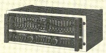
Yamaha CR-840
[… missing content]
trol is initially set to the loudest that one expects to listen, with the LOUDNESS control at its flat, or maximum, setting. Then, turning LOUDNESS counterclockwise reduces the volume in ten steps and provides progressively greater amounts of bass and treble boost.
In the rear of the receiver are insulated spring-clip speaker connectors and binding posts for the AM and FM antenna inputs (plus a coaxial connector for a 75-ohm FM antenna). Standard phono jacks are used for the various signal inputs and outputs. Instead of the usual ferrite-rod AM antenna, the Yamaha CR-840 comes with a small shielded-loop antenna that is physically separate from the receiver and can be mounted on it or on some nearby surface with an adhesive pad. There are three a.c. convenience outlets, one of them switched.
The Yamaha CR-840 is supplied in a wood en cabinet that measures 20 inches wide, 6 1/2 inches high, and 15 1/4 inches deep. It weighs about 30 pounds. Price: $510.
Laboratory Measurements. The Yamaha CR-840 is a rather large and heavy receiver for its power rating, and this was reflected in the ease with which it withstood the FTC-mandated one-hour preconditioning at one third rated power. The ventilating grille be came only moderately warm over the output-transistor heat sinks, and elsewhere the receiver was just barely warm to the touch.
With both channels driving 8-ohm loads at 1,000 Hz, the outputs clipped at 80.7 watts per channel. The clipping power at 4 and 16 ohms was 108 and 51.5 watts, respectively. The IHF clipping headroom was 1.29 dB, and the dynamic headroom was 1.65 dB. The harmonic distortion of the CR-840 was so low that without the most advanced test instruments it would have been impossible to measure it (and, in any case, it was not easy!). At 1,000 Hz the total harmonic distortion (THD) was under 0.001 percent at 0.1 watt output, rising to 0.0012 percent at 10 watts, 0.0036 percent at the rated 60 watts, and 0.015 percent at 80 watts, just at the onset of clipping. The inter-modulation distortion was about 0.005 percent from 10 to 40 watts output, reaching 0.008 percent at 60 watts and 0.011 percent at 90 watts. It also rose at very low power levels, reaching 0.05 percent at 0.1 watt. This low distortion was maintained over the full audio-frequency range. At rated power the THD was 0.005 to 0.006 percent from 20 to beyond 10,000 Hz, rising to 0.0075 percent at 20,000 Hz. At reduced power levels the distortion was even lower, typically well under 0.0025 percent.
The amplifiers of the CR-840 had a slew rate of 12 volts per microsecond, and the IHF slew factor was 3.1. They could be driven to a reference output of 1 watt by an input of only 15 millivolts (mV) at the aux input or 0.27 mV at the phono input. The corresponding A-weighted signal-to-noise ratios (S/N), referred to 1 watt, were 85 and 81.4 dB (exceptionally good S/N performance). The phono input overloaded at 190 mV at 1,000 Hz, but when the overload was measured at 20,000 Hz and converted to its equivalent value at 1,000 Hz it was 105 mV. This is not seriously low, but it is below the signal-handling abilities of many of today's amplifiers and receivers. The measured input termination of the phono pre-amplifier was 48,000 ohms in parallel with a rather high capacitance of 550 picofarads.
The bass and treble tone controls had conventional characteristics. The PRESENCE control action was centered between 3,000 and 4,000 Hz instead of at the lower frequency typical of most midrange tone controls. Yamaha's nomenclature is appropriate, since the control principally affects the sense of presence in the program rather than its overall frequency balance. The LOUDNESS contours were as claimed, with a very mild boost action over most of the control range and a much stronger effect in the last couple of steps. The low-frequency filter had a 12-dB-per-octave slope (its measured response was down about 2 or 3 dB at 20 Hz), and it functioned as an effective infrasonic filter. The high-frequency filter, on the other hand, had an ineffectual 6-dB-per-octave slope starting at 6,500 Hz.
The RIAA phono equalization was extremely accurate, with the response varying only 0.5 dB overall from 30 to 20,000 Hz and down 1 dB at 20 Hz. When the phono response was measured through the inductance of typical phono cartridges, there was a broad, slight rise in output over most of the upper midrange and treble, reaching a maximum of about 1 dB at 15,000 Hz before re turning to the reference level at 20,000 Hz.
The FM-tuner section had an excellent 50-dB quieting sensitivity of 14.5 dBf (2.9µV) in mono and 37 dBf (39 uV) in stereo. The IHF sensitivity in mono was almost the same as its quieting sensitivity, 14 dBf (2.7 uV). For weak-signal reception, the CR-840 has excellent properties, with the "distortion" consisting mostly of actual third-harmonic distortion. This provides more listenable reception of very weak signals than in the more usual situation where the weak-signal "distortion" consists mostly of hiss (which is much more audible than harmonic distortion under these conditions).
The ultimate S/N at 65 dBf (1,000 µV) was an excellent 79.2 dB in mono and 71.3 dB in stereo. The distortion at that signal level was only 0.054 percent in mono and 0.093 percent in stereo (in the wide i.f.-bandwidth or Local receiving mode). These figures are close to the residual distortion levels of our signal generator. They were obtained with the OTS/MUTING disabled; with it on, the typical mono distortion ranged between 0.06 and 0.09 percent, depending on the accuracy of the initial tuning when the knob was released. The stereo threshold was 21 dBf (6 µV), and the muting threshold was 17.3 dBf (4µV).
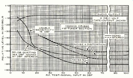
--- R.F. TEST-SIGNAL INPUT IN DBF
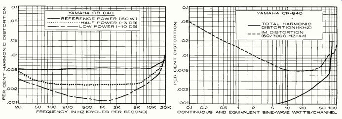
----- FREQUENCY IN HZ (CYCLES PER SECOND) CONTINUOUS AND EQUIVALENT SINE-WAVE
WATTS/CHANNEL.
The stereo-FM frequency response was al most ruler-flat, rising slightly at high frequencies to +0.7 dB at 15,000 Hz. The CR-840 does not use a low-pass or notch filter to remove the I9-kHz pilot carrier components from the audio. Instead, a pilot-signal-canceller circuit is built into the multiplex integrated circuit, and its effectiveness was demonstrated by the-65-dB level of the 19-kHz pi lot carrier in the audio (the 38-kHz component was undetectable, less than-90 dB). The stereo channel separation was also impressive-better than 46.5 dB from 30 to 2,500 Hz (and exceeding 50 dB between 100 and 2,000 Hz) before falling smoothly to 32 dB at 15,000 Hz. When the BLEND circuit operates, the separation is reduced to about 7 to 9 dB at all frequencies.
Other FM-tuner performance characteristics included: capture ratio 1.9 dB at 45 dBf (100 µV) and 1.53 dB at 65 dBf (1,000 µV), AM rejection 68 and 70 dB, respectively, at the same signal levels, and image rejection 73.5 dB. In the DX (narrow-i.f.) mode, the alternate-and adjacent-channel selectivity measurements were respectively 79.1 and 25.6 dB (the latter is extraordinarily high, by far the best we have ever measured on an FM tuner). In the LOCAL (wide-band) mode, which is the usual operating condition of the CR-840 in our area, the selectivity figures were 50.3 and 9.4 dB, respectively, still very adequate. The tuner's hum level was 68 dB below 100 percent modulation. The frequency response of the AM-tuner section was typical: down 3 dB at 20 Hz and 6 dB at 2,800 Hz.
Comment. Our test results on the Yamaha CR-840 receiver not only confirmed its very impressive specifications in all important respects (and surpassed them in many), but they strongly suggested that it is an outstanding product on any absolute scale of measurement without regard to price.
The controls and general tuning and handling "feel" of the CR-840 were up to Yamaha standards, which are among the highest in the industry. To us, the dual program selector (for listening and taping) and the separate loudness compensator (one of the very few truly usable loudness systems) are desirable features that set Yamaha receivers apart from their competitors, and we were happy to see both retained in the components that are part of the 1979 product line.
Judging from what we heard on the AM band, the Yamaha shielded-loop antenna is no more or less effective than the usual ferrite rod. The rather high phono-input capacitance of the CR-840 suggests that it should be used with cartridges that operate best with higher values of shunt capacitance.
The muting and OTS systems operated flawlessly. No sound whatever is heard from the speakers until a second or so after a station has been tuned in correctly. Then the sound comes up softly, with no trace of a click or thump. The effect when tuning off a station is just as smooth. The OTS makes it perfectly feasible to tune with the SIGNAL QUALITY meter alone for a rough maximum reading (even though no sound is heard). Releasing the tuning knob will then let the receiver tune itself in slowly until the channel-center meter pointer nears the center of its range. Only at that point will the receiver un-mute, and the final tuning point, according to our measurements, will provide very nearly the lowest possible distortion-lower, in any case, than one is likely to obtain by conventional manual tuning.
We have not touched upon Yamaha's many novel and interesting circuit and design features, which are referred to in their literature. Suffice it to say that they make it possible for a moderate-price receiver to provide performance that would have been unimaginable only a short time ago.
+++++++++++++
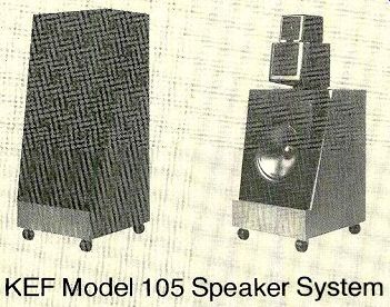
KEF Model 105 speaker system
DURING the past year or two, we have read much about the KEF Model 105 speaker system, principally in the British hi-fi press. Without exception, the subjective comments have been most enthusiastic, and as we learned more about this unusual product we looked forward to putting it through its paces in a familiar environment. We have now had the opportunity to make such an evaluation.
It is a little hard to know where to start when describing the Model 105. Its appearance with its grille removed is distinctive: a two-tier superstructure atop a moderately large floor-standing bass section. The system was designed to minimize time-delay distortions, and one result of this effort is its unusual shape (it has been remarked that without its grille the Model 105 looks like a pregnant robot). The midrange and high-frequency drivers of the three-way system are individually housed in molded, fully sealed enclosures whose rounded corners and edges are said to reduce diffraction effects that could disturb the phase coherence of its total output. The two drivers form a separate "head" that is adjustable over an angle of ±30 degrees in azimuth and ±7 degrees in elevation.
The midrange frequencies are radiated by a small driver whose Bextrene cone measures about 4 1/2 inches in diameter. At 2,500 Hz there is a crossover to a 2-inch Mylar-dome tweeter, and the crossover from woofer to midrange takes place at 400 Hz. The bass frequencies are radiated from a 12-inch Bextrene-cone woofer housed in a 2.5-cubic-foot fully sealed enclosure. The driver levels are factory set, and the Model 105 has no user-adjustable balance controls. The entire speaker system, which weighs about 80 pounds, is mounted on ball casters that simplify moving it about.
The purpose of the rotatable and tillable mid/high-range driver head is to ensure a uniform frequency response throughout a specific listening area (which KEF calls the "listening window") and thus provide a stable stereo image as one moves about. This adjustment is facilitated by LED's installed in a re cess in each head so that their light is visible (through a narrow "window") only to some one in a position to hear the full range of frequencies being radiated by the drivers. To orient the speakers, a knob in the rear of each head is set to LISTENING WINDOW and a steady signal (such as interstation hiss from an FM tuner) is applied to both speakers. If necessary, the heads are rotated and tilted so that both LED's can be seen from all portions of the room where listeners are expected to be. Then the knobs can be set to OFF or one of their power-indicator positions. These latter correspond to peak-power levels into the speaker (actually, into an 8-ohm load) of 40, 50, 60, 80, 125, 150, and 200 watts (the last is the maximum power rating of the speaker).
The flashing of one of the LED's is easily visible anywhere in the chosen listening area (even a very brief overload will cause the light to glow long enough to be seen) and indicates that the previously selected power level has been exceeded.
In the rear of the adjustable head are fuses for the midrange and high-frequency drivers, plus a spare for each, and the knob for adjusting the vertical tilt of the head. A black grille cloth on a wooden frame hides both the super structure and the woofer cone from view. The exposed portions of the enclosure are covered with walnut veneer. The KEF Model 105 is 38 inches high, 18 inches wide, and 163/4 inches deep. The speakers are sold only in matched pairs. Price: $1,900 per pair.
Laboratory Measurements. The midrange and high-frequency response of the KEF Model 105 in the reverberant field of our listening room was measured first with each speaker's head oriented toward the micro phone (which was in our usual listening position) and again with the heads facing directly forward. The only difference between the two sets of curves was in the spread, or difference, between the high-frequency outputs from the two speakers, one of which was placed about 30 degrees off the axis of the microphone. The integrated output, corrected for the room response, was identical in both cases, as it should have been since our test method essentially measures the total acoustical power radiated by the speakers. Our curves showed that the tweeter dispersion was only moderately wide. This is not surprising in view of its relatively large dome diameter and KEF's controlled-dispersion design approach. However, when the driver heads were positioned correctly, the pair of KEF Model 105's distributed all frequencies evenly throughout the listening area.
The woofer response, when measured separately, was very strong in the low bass but rolled off gently above 100 Hz. At the nominal 400-Hz crossover frequency it was about 13 dB below the average level in the 40-to 100-Hz range (the woofer output varied only ±1 dB from 37 to 130 Hz). But since the reverberant-field measurement showed no sign of an output drop in the crossover region (in fact, there was a slight increase at about 250 Hz), we assume that the matching of the drivers and the properties of the crossover net work compensate for this apparent anomaly.
The response of the KEF Model 105, including all the "bumps" and "dips" that are usually associated with room/speaker interaction, was within ±2.5 dB from 35 to 20,000 Hz. Furthermore, it was almost perfectly flat in the uppermost octave, varying no more than ±0.2 dB from 8,000 to 20,000 Hz; no doubt it extended well above 20,000 Hz, but our room calibration ends there and we do not attempt to extend acoustic measurements beyond the audible range.
The Model 105 would be noteworthy for its wide, smooth, uniform frequency response, but in some ways we were even more impressed by the low distortion of its woofer response. Many of the distortion readings we obtained were not much higher than one measures with amplifiers. The distortion was typically from 0.2 to 0.3 percent in the 80-to 100-Hz range with either 1 or 10 watts input.
With 1 watt the distortion was still a mere 2 percent or so at 30 Hz, and with 10 watts it measured 5.6 percent at that frequency.
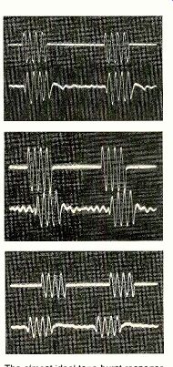
----- The almost ideal tone-burst response of the KEF 105 at (top
to bottom) 100, 1,000, and 10,000 Hz. The up per traces are the input signals.
The measurements we had made up to this point left us in no doubt that the KEF Model 105 is an outstandingly fine speaker. But what were the specific results of its unusual physical configuration and the rather extraordinary effort to optimize its transient-response characteristics? Tone bursts were reproduced in the almost-perfect manner we have come to associate with speakers that are really free of major time-delay distortions (as opposed, of course, to those that merely claim to be). The bursts were almost ideal at all frequencies and with the microphone in any position in front of the speaker. It was not necessary to search for a few special frequencies and microphone positions in order to obtain recognizable tone-burst photos (the usual procedure with most speakers). The pictures we made at arbitrarily selected frequencies and microphone locations were almost identical in character to the bursts we saw at every other frequency and position we tried.
The sensitivity of the Model 105 was exactly as rated: it delivered an 86-dB sound-pressure level at a 1-meter distance when driven by 2.83 volts of random noise in the octave centered at 1,000 Hz (corresponding to 1 watt into 8 ohms). Its impedance curve showed a number of up and down variations, but they were within fairly narrow limits. The maximum was about 25 ohms at 2,700 Hz, and minima of 6 to 7 ohms were observed at 100 and 600 Hz. In our view, the speaker's nominal 8-ohm rating is well justified.
Comment. Our subjective judgment of the sound of the KEF Model 105 was, most of all, that it was very smooth, with strikingly less coloration in any part of the audio range than we are accustomed to hearing from speakers of any kind. It has been likened to the sound of a good full-range electrostatic speaker, but not having one of that type on hand for a side-by-side listening test, we can only say from memory that the comparison is not an unreasonable one.
KEF claims, and we verified, that one can move around these speakers, and even between them, with remarkably little subjective shift of the sound pattern. In this respect they resemble some omnidirectional speakers, al though they are certainly not omnidirectional, nor do they sound like any omnis we have ever heard. Compared with our regular acoustic-suspension systems, the Model 105's are somewhat "airier" and less heavy-sounding, although their deep-bass response is not very different from that of our usual speakers. The KEF Model 105 seems to us to incorporate the best qualities of dynamic drivers with an absolute minimum of their weaknesses.
KEF's literature describes the highly sophisticated computer-assisted design and testing methods that went into the creation of the Model 105 (and are still used regularly in production testing). By use of "Fast Fourier Analysis" of the speaker's response to an impulse, the full amplitude and phase response of the system is derived. In production, every driver is measured individually, and its characteristics are computer-matched to those of the other drivers and the crossover components that make up a matched pair of systems.
Just as Rolls-Royce is reputed to keep data on the individual hides and wood veneers that go into their cars, KEF has the complete data on all parts of every one of their speaker systems stored in their computer files. Thus, if a re placement driver is needed in the future, a unit can be supplied that will exactly match the performance of the original one and there fore "harmonize" with the rest of one's existing system.
A brief report such as this cannot cover all the fascinating details of this system, but it is worth mentioning that every pair of Model 105's is given a critical listening test in a suit able environment, using music and other pro gram material, before being shipped out. This is in addition to the myriad of more technical tests. One reaction to the KEF Model 105 can best be expressed by saying that it is one of the few speaker systems we have tested that we would unreservedly enjoy owning.
+++++++++++++++++++++++++
Soundcraftsmen SP4002 "Signal Processor/Preamplifier"
THE Soundcraftsmen SP4002 "Signal Processor/Preamplifier" is a very versatile control center combining a high-quality phono preamplifier and a ten-octave graphic equalizer. The separate groups of equalizer slide controls for the two channels provide a nominal +15-dB range in bands centered at 30, 60, 120, 240, 480, 960, 1,920, 3,840, 7,680, and 15,360 Hz. Level-adjustment controls compensate for the overall gain shifts that can occur when several equalizer slide controls are used simultaneously.
The SP4002 is actually more than a graphic octave-band equalizer. It is a fully flexible tape-recording control center with tape-monitoring and cross-dubbing connections selectable by pushbutton switches. A pair of front-panel jacks parallels the rear tape-recorder connections for one machine. Two EXT LOOP circuits, controlled by front-panel pushbuttons, connect various accessories (such as Dolby, dbx, or other external signal processors) into the signal path.
Four pushbuttons provide a choice between PHONO 1, PHONO 2, TUNER, and AUX program inputs. The signal-processor controls are a group of buttons at the lower center of the panel. Two control the EXT LOOP circuits, one (EQ) inserts the graphic equalizer, which is otherwise completely bypassed, into the normal signal path, and another inserts the equalizer in the signal path going to the tape recorders. A MONO button parallels the two channels, and another inserts a SUBSONIC FILTER into the signal path. The two headphone jacks on the front panel have a separate amplifier capable of driving phones of from 8 to 2,000 ohms impedance. Plugging phones into JACK 1 shuts off the preamp feed to the power amp.
The only knobs on the front panel of the Soundcraftsmen SP4002 are for the VOLUME and BALANCE controls. On the rear apron are the various signal input and output jacks plus a number of special features associated with the phono inputs. Near each phono input are two gain controls adjustable over a ±20-dB range. Normally, the detented center (0-dB) setting is used for typical moving-magnet cartridges. A very-high-output cartridge may re quire a reduced gain setting, and some moving-coil Cartridges can be used when the gain is set to +20 dB. The paired controls permit separate gain adjustments for each channel of each phono input.
There are also two groups of tiny switches near the phono inputs on the rear apron of the preamplifier. They resemble integrated circuits and are operated by pressing their small plastic actuators with the tip of a ballpoint pen. Each switch group is divided into two sections, one for the left and one for the right channel of that phono input. One switch changes the input resistance from the normal 47,000 ohms to 100 ohms (for moving-coil cartridges). The others add capacitance to the normal 50-picofarad (pF) input capacitance of each input, enabling the total cartridge-load capacitance (exclusive of the cables from the record player to the amplifier) to be adjusted from 50 to 800 pF in 50-pF steps.
The Soundcraftsmen SP4002 can switch the a.c. power to a high-power amplifier, since its four switched a.c. outlets can handle a total of 1,000 watts. There are also two unswitched outlets. The SP4002 is finished in flat black with accents of silver on the front panel, and it has a pair of sturdy handles. (The wood side panels can be removed for standard rack installation.) The unit is 19 inches wide, 7 inches high, and 11 inches deep; it weighs 28 pounds. Price: $699.
Laboratory Measurements. With the IHF standard load of 10,000 ohms in parallel with 1,000 pF, the outputs of the SP4002 clipped at 11.8 volts rms at frequencies from 20 to 1,000 Hz. At 20,000 Hz the maximum output was about 5.5 volts, which should be more than adequate under any circumstances. The total harmonic distortion at a 1-volt output was 0.006 percent at 20 Hz, 0.0018 percent at 1,000 Hz, and 0.01 percent at 20,000 Hz. Intermodulation distortion was 0.002 percent at 1 volt and 0.003 percent at 10 volts. For a reference output of 0.5 volt, the high level (TUNER or Aux) sensitivity was 85 millivolts (mV). The phono sensitivity was adjustable from 0.096 to 10 mV. The A-weighted noise output was unmeasurable (less than 100 microvolts, or -74 dB referenced to 0.5 volt) through both the AUX input and the phono in put when the phono gain was set to 0 or-20 dB. At the maximum phono-gain setting (which would be used for a moving-coil cartridge), the output noise was -63 dB referenced to 0.5 volt.
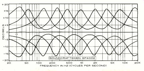
-------- FREQUENCY IN HZ (CYCLES PER SECOND)
The phono-overload levels were 115 mV at a 0-dB (normal) setting and 95 mV at the seldom-required minimum gain of-20 dB. At maximum gain (the moving-coil setting), over load occurred at a 15-mV input. The phono input resistance was 47,000 ohms (100 ohms when set for moving-coil cartridges), and the capacitance introduced by the input switches was within 20 percent of the indicated values.
The RIAA phono equalization was within +0.5,-1 dB of ideal from 20 to 20,000 Hz. It was affected hardly at all by the inductance of a phono cartridge at the input, which made less than a 0.5-dB change at any frequency.
The infrasonic filter began to roll off the response below 30 Hz, and it was down about 4 dB at 20 Hz. The equalizer controls are capable of providing a nearly infinite number of response curves. With the controls centered, the response is ruler flat even when the EQ button is engaged.
Comment. The equalizer section aside, the Soundcraftsmen SP4002 is obviously a highly versatile control center whose performance and sound quality should satisfy the most critical listener. We obtained fine results using several different phono cartridges-including a high-output moving-coil unit. It should be noted that Soundcraftsmen recommends the SP4002 only for use with moving-coil cartridges that deliver at least 0.28-mV output.
The greatest appeal of the Soundcraftsmen SP4002 will probably be to people who have definite ideas about the octave-to-octave balance they want to hear from their music systems and are willing to trust their ears in set ting the equalizer controls. Without question, the SP4002 is at least as good as any comparable equalizer we have seen (barring those with more than ten bands, which are usually more expensive and harder to adjust). In our view, a good octave-band equalizer and a high-quality, very flexible control preamplifier with above-average tape-recording facilities make a fine combination, and the Soundcraftsmen SP4002 is the proof.
Also see:
Link | --KEEPING IT CLEAN--RECORD HYGIENE: The scanning electron microscope reveals some fascinating secrets, by GEORGE ALEXANDROVICH
Link |
Source: Stereo Review (USA magazine)