Digital Audio: A Primer (Feb. 1981)
By David Ranada
PRICIER Now that a home digital-audio play back system is on its way, it's high time that market-wise audiophiles learned the basics of digital audio so they won't be confused or bamboozled by advertising copy or product brochures. The fundamental principles of digital sound are really quite simple-easier to understand, in fact, than other, more familiar aspects of audio, such as, for example, stereo FM. This short primer is meant to give the reader a confident feel for those principles and will therefore ignore the frills-such digital-audio esoterica as DAC monotonicity, sin X/X compensation, phase-compensated filters, floating-point encoding, and dither signals.
DIGITAL audio can perhaps best be explained through an analogy. Suppose a cabinetmaker friend of yours wants to make a duplicate of an ornate table you own. You could lend him the original table (corresponding to live music) or perhaps give him a scale drawing (an analog recording) from which he could make his copy.
The first method might be both risky and impractical; the second would require highly accomplished drawing skills. A third method would be to send him a "digital recording"--a sheet of paper on which is written a list of detailed measurements of the original table. As long as he knows exactly which measurement applies to which part of the table, the degree of fidelity with which the table can be reproduced depends solely on (1) the accuracy of the measurements you send and (2) how well your friend can duplicate them using his own tools. Likewise, the fidelity of a digital-audio system depends only on (1) the accuracy and precision of the measurements made on the original audio waveform and (2) the ability of the playback equipment to turn those numbers back into a varying audio voltage.
The analogy points up another important aspect of the digital process: its immunity from error. If your cabinetmaker friend lives two thousand miles away, the chances that the original table will arrive undamaged (distorted) are low. Distortion is also difficult to avoid in even the most carefully drawn scale representation. And even if a perfect scale drawing were to arrive intact at its destination, it still might have been folded, spindled, or otherwise mutilated. If irreparable damage has been sustained by the drawing (read "record grooves"), there goes any chance of exact duplication.
But digital recording is quite immune to these types of signal degradation: as long as the measurement numbers on the list can be read at all, a duplicate table can be made.
Your friend can even "regenerate" a dam aged copy of the list by recopying it by hand. And you could yourself make the list even more immune to damage by sending several copies of it on the same sheet of paper. In this way, even if much of the sheet were to be destroyed there would be enough surviving "redundant" data to ensure proper completion of the table.
Digital audio similarly has a resistance to error. A digital-audio recording contains not only the original waveform measurements but also error-detection and-correction data. These data enable the digital playback system to tell whether the original measurements have been damaged and how to correct the errors using redundant data placed in the recording.
So far, so good-but you're right: Beethoven's Fifth is not like a table (although I've heard some pretty wooden performances of it). How are measurements made on an audio signal so that one can safely say that it is recorded with fidelity? And how are those measurements translated back into an audio signal so that it is (almost) indistinguishable from the original? The answers are: (1) through the very high rate of the conversion of the audio signal to and from numerical measurements, and (2) through the accuracy and precision of the measurements themselves. In other words, digital audio operates very fast and very carefully. These two aspects of the process relate to the two most fundamental operations in digital audio: sampling and quantization. To discuss these we'll have to com plicate our analogy and dive just a bit deeper into digital theory.
Sampling
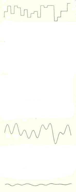
Let us say that the table to be copied has a rather ornate top, the edge of which consists of a compound "pie-crust" curve. And if you look closely at the table edge, you'll see various narrow undulations, some put there by the original maker's tools, others produced by wood grain, cuts, or scratches. Greatly magnified, a section of it might look like this:
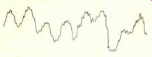
This same curve might also be an audio waveform as displayed on an oscilloscope screen. In this interpretation, time runs from left to right and the height of the curve represents the audio voltage at any instant.
High frequencies (the narrow peaks) are undulations that occupy short time periods;
low frequencies take longer and appear wider. If we want someone to reproduce this tracing, what kind of measurements should be made and sent? One simple measurement method is called sampling. To sample the table edge you would make a series of regularly spaced horizontal measurements (samples) of the distance of the table edge from some baseline (such as a line down the center of the table). Your friend would then take your measurements, plot them out on a piece of wood using the exact same horizontal spacing as you did, and cut along the resulting plot. In audio, you'd measure the audio voltage at regular intervals. On play back, a circuit would generate the same voltages, with the same spacing in time, as are specified by the list of measurements.
What is the minimum spacing between measurements that will make it possible to capture all the fine detail in the original table edge (or waveform)? You can get an intuitive feel for the answer by considering the following. If the narrowest undulation of the table edge is V64-inch wide and measurements were taken every 1/4 inch, you'd miss all the fine details between the '/4-inch samples. The table might, in fact, have a deep but narrow 1/64-inch cut which was straddled by two 1/4-inch samples. And if one of the 1/4-inch measurements landed right in the cut, your friend would end up with a gouge at least 1/4-inch wide on his table edge, for he has no way of knowing from the list of measurements you supplied that the cut was originally only 1/64-inch wide. In digital audio, samples that are too widely spaced also lead to incorrect waveform re construction. To avoid this, you might take as many closely spaced samples as possible, but this would create billions of measurements, not all of them necessary. Fortunately, there is a simple way to determine how frequently you need to take samples.
THE mathematical model of the waveform sampling process says that the spacing be tween the samples must be at most no more than one-half the length of the narrowest table-edge undulation you want to record (which is to say that the narrowest wiggle of interest must receive at least two measurements). Translated into audio terms, the sampling must take place at least twice as frequently as the highest frequency you wish to record. If the audio waveform includes a 20,000-Hz signal, samples of it must be made at least 40,000 times per second. If the sampling rate is too low, an original high-frequency waveform (the 1/64-inch cut) would come out in replay as an un wanted low-frequency signal (the 1/4-inch gouge). This is called "aliasing" distortion, because the spurious low-frequency signals thus produced are to the originals as a false identity, or "alias," is to a real person.
Two things must be done to eliminate aliasing. First, the sampling rate must be at least twice the highest frequency you wish to sample (this is called the Nyquist frequency). Second, frequencies above the Nyquist frequency must be eliminated from the signal entering the sampling process. In digital audio this is performed by a very sharp-cutoff low-pass (high-frequency-cut) filter, which is named, sensibly enough, an anti-aliasing filter. Such a filter is generally the first circuit an audio signal encounters as it enters a digital-audio recorder.
(The cabinetmaker's equivalent might be a machine that rounds off sharp corners by a sanding process.) The sampling rate should also be as low as possible so that the number of measurements is kept down to a practical level. In order to preserve the digital-audio system's frequency response out to 20,000 Hz, the sampling rate chosen in today's digital recorders is above 40,000 Hz. The anti-aliasing filters are designed to cut out frequencies above 20,000 Hz. The sampled output from the filter is a smoothed version of the original, all the ultrasonic frequencies having been removed (it's okay-you can't hear them):
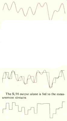
It is this waveform that is considered to be the "original signal" to be copied by the digital recording process.
Now, the circuits that are used to measure the samples need a little time to do so.
Therefore, a device that is called a sample-and-hold circuit (S/H) "freezes" the audio voltage at the instant of sampling, holds it there while the measurement is made, and at the next sampling time freezes the audio signal again. Here is the S/H output over laid on the filtered original signal:
The S/H output alone is fed to the measurement circuits: (see above diag.)
If every step so far has been done correctly (no too-high frequencies, samples regularly spaced, audio signal precisely frozen), in theory no degradation of the original signal has occurred; it has merely been transformed into something suitable for electronic measurement. But the measurement process, even if it is done perfectly, does introduce some errors, and we should look a little closer to see what they are.
Quantization
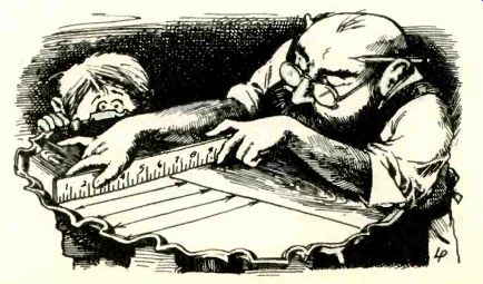
The second fundamental principle of digital recording, "quantization," refers to the generation of a number during the measurement process. To quantize the table-edge waveform, at each sampling point you'd use a ruler to measure the distance in inches be tween the table edge and a reference line drawn down the center of the table. During this process, you must round off the measurement to the nearest marking on the ruler. If the ruler has marks spaced only every 1/2 inch, then the set of measurements will be to the nearest 1/2 inch. Obviously, if the table edge has bumps and dips that are only 1/8-inch high, 1/2-inch resolution is not sufficient to "record" the table accurately.
With an audio signal, what is quantized is the voltage of the audio signal at the sampling instant (specifically, the voltage frozen at the sampling point by the S/H). A circuit called an analog-to-digital converter (ADC) compares the audio voltage with the electronic equivalent of a ruler and generates the electronic code number which most closely represents the input voltage.
On playback, a digital-audio system will retrieve the numbers from the recording medium (digital tape or disc) and feed them into another specialized circuit called a digital-to-analog converter (D/A or DAC).
This circuit generates an output voltage corresponding to the code numbers using the same voltage/number relationship as the original ADC.
The ruler-marking problem we encountered above with the table also exists in dig ital audio. How fine must the quantization steps (voltage levels) be before high fidelity can be achieved? If the audio signal had meaningful undulations of I millivolt (one thousandth of a volt) and the ADC could only distinguish changes of I volt, there'd be a problem. However, unlike the case of the sampling-rate problem (simply sample at a rate twice that of the highest frequency), there is no easy answer here.
The difference between the recorded number and the actual value you would get if the ruler had infinitely finely spaced markings is a signal error. In the case of the table, your friend would end up with an edge which closely, but not exactly, matched the original. The audio equivalents of such differences between input and out put are noise and distortion. This quantizing noise can be minimized by using more closely spaced markings on your electronic "ruler," but there are ramifications to this:
First, increasing the resolution (the fineness of the changes the system can distinguish) also increases the length of the number generated (think of 3 inches as opposed to, say, 3.025 inches), making compact storage of the numbers more difficult. Second, with digital audio it becomes increasingly difficult for electronic reasons to make extremely fine markings on the "ruler" so that ac curacy does not suffer. Nonetheless, that is what we must do, for only an increase in the resolution will decrease the amount of noise and distortion generated by the record/playback system in digital audio.
The resolution of a digital-audio system is measured in "bits," each bit being a power of 2. Thus a sixteen-bit digital-audio sys tem divides the voltage range being used into 216 (65,536) discrete levels, each one identified by a sixteen-place binary number ("binary" meaning made up only of 0’s and 1’s). The theoretically best signal-to-noise ratio obtainable with such a system is 98.08 dB, each bit adding about 6 dB to a digital-audio system's noise performance (equivalent to a doubling of the number of mark lower performance level is obtained in practice owing to inaccuracies in the ADC/DAC system and noise added by the S/H and filter stages.
Signal Reconstruction
We've been mostly concerned with re cording up till now. With playback, however, additional problems arise. A major one concerns the numerical data as it comes off the digital tape or disc; another has to do with the DAC-regenerated signal.
Numbers do not come off a digital tape or disc at a steady rate, yet the accuracy of the digital process depends on the regularity of the spacing of the samples in both recording and playback. In the table analogy, it's as if the cabinetmaker had someone reading back the list of measurements to him some what haltingly and not exactly when he needs them, with the result that the plotted horizontal spacings come out unevenly.
Such deviations from regularity would be perceived in audio either as noise, distortion, or wow and flutter. Eliminating this problem is easy if a kind of "scratch pad" is used on which a backlog of the numbers is stored. Numbers can be removed from the scratch pad at a regular rate regardless of how irregularly they are entered on it. As long as the pad does not become full or empty, wow, flutter, and other timing-related distortions can be eliminated. And this is just what is done with a digital-audio system; the scratch pad is made of electronic digital memory circuits (such as those used in computers), and the timing of the release of the numbers is regulated by a crystal oscillator (as in digital watches).
The output of a DAC receiving the regularly timed numbers looks like this:
You will note that it looks very similar to the S/H waveform in the "Sampling" section above, except that some of the levels have been changed slightly. This is because the quantization process has rounded off the S/H levels to the nearest quantization level. This vividly shows how distortion and noise arise from quantization. These traces, however, are of a four-bit quantization sys tem with a 25.8-dB signal-to-noise ratio at best. A sixteen-bit system would have much better performance.
If you analyzed this waveform mathematically. you'd find that it contains a copy of the original waveform (within the accuracy and precision of the quantization pro cess) plus a lot of extraneous high-frequency components. Fortunately, these components are related to the original signal in a special way: they all lie above the Nyquist frequency. Another very sharp filter is necessary to remove frequencies above the Nyquist frequency; this time it is called an out put-smoothing filter. Its output looks like this:
In our table-edge analogy, this filter would again be some sort of machine that fills in small holes and rounds off sharp edges.
If you took the difference between the output-smoothing filter's output and the original signal, you'd be left with only the noise and distortion products:
Although you can't tell by looking, this noise and distortion is about 25 dB lower than the original signal level-exactly as predicted for a four-bit system.
Electronics
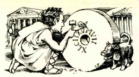
Engineer readers may be surprised at the lack of attention that has been given to bi nary numbers and other related aspects of digital audio. The simple fact is that binary numbers have little to do with the fundamental concepts of sampling and quantization. The numbers generated by the digital-audio process could just as well be Roman numerals chiseled into marble, although re cording and playback of such a "solid state" digital recording would be rather impractical.
"Digital" does, however, have a very specific meaning in electronics: it is a system that utilizes pulses to signify binary numbers. What makes binary numbers so advantageous for digital audio is that a binary number is composed of only 0s and 1s corresponding to an open or a closed switch, respectively. And it happens that transistors make excellent electronically controlled switches; it is easier to turn a transistor into a switch than into an amplifier. So integrated circuits containing hundreds or thousands of interconnected transistor switches can cheaply and reliably perform the necessary digital operations in a digital-audio system. Integrated circuits have, in short, made digital audio practical for home use.
The official name for the digital process described here is "linear pulse-code modulation (PCM)"--linear because the quantization levels are always equally spaced; PCM because a numerical code made up of pulses is modulated by the audio signal.
And it should be added that there are also other, less common ways to digitize audio (delta modulation, for example).
A Review
To neap, digital audio is based on the concepts of sampling and quantization. A signal entering the system is first filtered to remove any extraneous high-frequency in formation (by the anti-aliasing filter); then it is sampled at precisely regular intervals (by the sample-and-hold circuit), and the samples are measured (quantized) by an analog-to-digital converter. The numbers generated by the ADC are stored on disc or tape. On playback, the numbers from the disc or tape are regularly fed into a digital-to-analog converter, resulting in a squared-off signal containing the original signal de graded by quantization errors. The DAC output is then fed through an output-smoothing filter to retrieve the original in put waveform (minus the extraneous high-frequency information).
Frequency response is flat for a digital-audio system up to the Nyquist frequency.
A high signal-to-noise ratio is the result of high resolution in the quantization. Wow-and-flutter is eliminated by precise control of signal timings. Freedom from error comes from the numerical, discrete nature of the process, a process which lends itself to self-correction and repeated copying with no degradation in signal quality. You need not build that table.
------
====================
Also see:
Digital Mastering--A Progress Report (Jan. 1979)
Regulars (Letters, etc.) (Feb. 1982)
Source: Stereo Review (USA magazine)