By Julian D. Hirsch and Craig Stark Hirsch-Houck Laboratories; Storksonic Studio
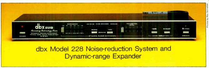
dbx Model 228 Noise-reduction System and Dynamic-range Expander
Size: 18 x 7 1/2 x 13 1/4 inches. Price: $499
dbx Model 228 (whose full name is I the "Type II Tape/Disc Noise Reduction System & Dynamic Range Expander") is a compact, versatile multifunction signal-processing accessory that operates in the signal path between the preamplifier and power amplifier or in a monitor loop of the preamplifier. It has three distinctly different basic functions. As a dynamic-range expander, it can increase the dynamic range (in decibels) of any program by up to 50 percent. It is a recording and playback noise-reduction system, dbx Type 11, with separate encode/decode circuits that compress the signal by 2:1 during recording and expand it by the same amount during play back. Finally, it can decode the playback of dbx-encoded discs.
The dbx II noise-reduction system (the consumer version of the professional dbx I system) operates over the full audio-frequency range, making its noise reduction equally effective against hum and hiss. It also has internal high-frequency pre-emphasis during recording and a complementary de-emphasis during playback.
A feature of the dbx noise-reduction system is its relative independence of program level. Because of the system's extremely wide dynamic range, and because the same compression and expansion slopes are maintained over its full dynamic range, precise record-playback level matching is not required. As a tape-recording accessory, the system can theoretically double the dynamic range of a tape recorder. This offers the intriguing possibility of obtaining a 100-dB range from a cassette deck whose inherent dynamic range is only 50 dB. Even with allowance for variations in the placement of the compressed program within the avail able operating range, a dynamic range of 90 dB is achievable with cassette recorders. As with other encode/decode noise-reduction systems, the dbx II can only reduce the noise added during the recording and play back process and will not affect noise already in the program.
In the dbx disc system, phonograph records are cut with signals processed by a dbx encoder. When played back through a suit able decoder, these discs can deliver roughly the same dynamic range as dbx tapes up to 90 dB or so. Since the noise reduction is equally effective against rumble, the result is a total absence of the usual record noises.
The actual dynamic range of a dbx record is often limited by the master tape from which it was made. Many derive from analog masters, and no matter how good they might be, their background noise will certainly be higher than that of the dbx decoder. Nevertheless, the total silence in the background of these records is uncanny and adds greatly to their realism and impact. A similar limitation exists with respect to making or playing dbx cassette tapes. Un der most conditions the limiting "noise floor" will be established by external conditions and prevent the full potential of the system from being realized.
The final mode of the dbx Model 228 is dynamic-range expansion, which is applicable to any program source (including the playback of dbx-encoded discs or tapes after decoding-although it should not be needed with wide-dynamic-range program material). Virtually every recorded or broadcast program has undergone some degree of compression, limiting, or other dynamic-range restriction before it reaches the listener. The expander makes it possible to restore some of the lost dynamics, making a program more natural-sounding. In the Model 228, the expansion system operates completely independently of the tape-or disc-processing systems.
The dbx Model 228 is furnished with brackets for mounting in a standard 19-inch rack. Wooden sides are available as an option. The front panel contains two horizontal slider controls and a number of pushbuttons. In the center of the panel two mechanically interlocked buttons marked SOURCE and TAPE select the program input for the dynamic-range expander. One slider (EXPANSION) sets the amount of expansion over a calibrated range of 1.0 (no expansion) to 1.5 (maximum). The other (TRANSITION LEVEL) shifts the range of input-signal levels within the processor's operating dynamic range. A horizontal row of red and yellow LEDs shows the operating status of the expander at all times. Yellow lights extending to the left of center indicate the degree of gain reduction, and red lights extending to the right of center show the degree of increase. When no lights are lit, the gain of the expander is unity.
The two NOISE REDUCTION buttons are marked TAPE and BYPASS. The latter is normally engaged unless one is recording or playing back a dbx-processed tape. To their right is the dbx DISC DECODE button, which is mechanically interlocked with the others.
It is used for playing dbx-encoded discs.
The expansion system can be used, to any degree desired, at any time (it affects only the playback signal, after decoding). Set ting the EXPANSION slider to 1.0 is all that is needed to remove it from the system.
In the rear of the dbx Model 228 there are standard phono jacks for the signal in puts and outputs, which are normally obtained from the monitor-loop jacks of the associated equipment. Additional tape jacks on the rear of the Model 228 replace the functions of the amplifier jacks. There are three screwdriver-adjusted level controls for matching the output levels from the Model 228 in each of its modes. They are for convenience only, and do not affect the internal operation of its circuits.
Laboratory Measurements. There are few conventional measurements that can be made on a dynamic signal processor such as the dbx Model 228. A valid analysis of its operation requires separate access to its signal-modification and control circuits, which ...
------------
Comment. We used the dbx Model 228 as part of a music system, recording and playing back cassette tapes and expanding FM and phono programs. We also auditioned some recent dbx disc re leases that had been made from digitally taped masters.
When we reported on the original dbx disc decoder (STEREO REVIEW., November 1979) we were favorably impressed with its potential, but we noted that the only discs available at that time with dbx encoding were made from analog tape masters and that the master-tape noise, which might have been masked in a conventional record, was all too audible when the dbx process eliminated the record noise.
When we listened to digitally mastered records (from M&K and Chal font) with the Model 228, the effect was astonishing. For all practical purposes, the sound quality was nearly equal to some digital tapes we have heard. At no time was any background noise audible, including the set-down of the stylus on the record. The average level on these records is not particularly high (in fact, the undecoded cartridge output seemed considerably lower than that we normal ly find in other "audiophile" discs), and this no doubt reduces the normal play back tracing distortion.
Best of all, the dynamic range of these discs is unsurpassed by anything so far available for home use. As expected (but still coming as a surprise) the peak power requirements of a system to play these discs are far beyond what one would have expected in the past. At moderate listening levels (which would not interfere with conversation or using a tele phone in the same room) the average power required with typical moderate-to low-efficiency speakers is 1 watt or less. The program peaks, however, often clipped a 200-watt-per-channel amplifier and lit the protection lights at the 200-watt level on a pair of KEF 105.2 speakers. With the PEAK HOLD meter indications on a McIntosh MC 2255 amplifier we could tell that the program peaks reached levels between 250 and 500 watts per channel with a moderate average listening level.
Although this may affect people's amplifier buying habits in time, the benefits are immense. This kind of reproduction must be heard to be appreciated-words are completely inadequate to describe it.
It does not yet duplicate "live" sound (probably an unattainable goal), but it is a giant step closer to bringing the real ism of a live performance into the home.
The dbx 228 is very easy to use with a cassette deck (if the deck has three heads, one can monitor the decoded output while making a recording). The improvement in the signal-to-noise ratio is dramatic. Under certain conditions, de pending on the program material and in put-noise spectrum, one may hear traces of noise modulation (the level of the pro gram background noise being modulated by high-level transient signals).
This was never obtrusive enough to be noticed without specifically listening for it (which, of course, we were doing). Al though dbx suggests recording at a nearly normal (0 dB) level on the recorder's meters, we suggest keeping the maximum average level under-5 dB if possible unless the recorder has exceptional high-frequency headroom. It is normally possible to sacrifice a considerable amount of noise reduction (when the noise in the final tape will still be well below that in the program) and gain ad vantages in high-frequency linearity and clarity by keeping the levels lower than usual.
We spent some time using the Model 228 as an expander. There have been many improvements in expanders in re cent years, and the Model 228 shows the results of that progress. While it is possible to create an unnatural surging of the program if maximum expansion is used, especially with such material as solo instruments where the gain changes are not masked by a more complex program structure, we found the dbx recommendations of an expansion slope of 1.2 to 1.4 with classical music and 1.3 to 1.5 with popular music to give the best results. When the TRANSITION LEVEL is set according to instructions (so that the average program level tends to balance the "on" time of the yellow and red lights), there is a minimum change of overall perceived level, yet during quiet or low-level passages the yellow lights will be lit and the background noise greatly reduced (usually eliminated entirely). Used properly, the expansion of the Model 228 is never apparent to the listener-at least until it is switched off.
This is a sine qua non for any signal processor, whose operation must never be perceived directly.
The dbx Model 228 is one of the most useful single accessories one can add to a reasonably well-equipped music system.
Each of its operating modes is likely to be useful in some phase of the system operation, and if one does not already have a dbx disc decoder or one of the other dbx units, the Model 228 represents one of the neatest ways to realize their advantages.
------
...are not available externally. Our measurements consisted principally of verifying the maximum output voltage of the unit (rated at 7 volts and measured at just over that figure), the distortion of the expander section (rated 0.1 percent and measuring between 0.01 and 0.04 percent for output voltages between 1 and 5 volts at any expansion slope), and the output noise level of the unit. Since that was well below our 100-microvolt measurement limit under any control conditions, we were unable to verify the specification of-85 dB relative to 1 volt (unweighted), or about 50 microvolts.
Frequency response, as such, cannot be measured while compression or expansion is taking place, since the response of the sensing and control circuits determines the total response in a steady-state measurement.
With the expansion set to 1.0, the response of the Model 228 was flat from below 100 to 20,000 Hz and rolled off slightly at lower frequencies to-2 dB at 20 Hz. This satisfies the manufacturer's specification of 20 to 20,000 Hz ±1 dB.
We also measured the transfer characteristic (output voltage vs. input voltage) of the expander at expansion settings of 1.0, 1.2, and 1.5. The 1.0 setting, of course, gave a linear (1:1) relationship between input and output, and with the others the output varied more rapidly than did the input. The three curves intersected at one point (deter mined by the setting of the TRANSITION LEVEL control). Below that input, the expanded output curves fell much more rapidly than did the input, and above it the expanded output exceeded the unexpanded output by approximately the amount indicated by the ExPANsioN control setting.
==========
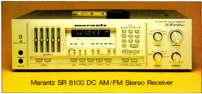
Marantz SR 8100 DC AM FM Stereo Receiver
Power Rating: 90 watts per channel; Size: 16.5 x 15 1/4 x 4 3/8 inches; Weight: 24 pounds; Price: $750
THE Marantz SR 8100 DC Computune receiver combines a digital-synthesis AM/ FM tuner with a direct-coupled amplifier rated to deliver its output into 4-ohm loads between 20 and 20.000 Hz at less than 0.06 percent total harmonic distortion. It is the first receiver we can recall seeing whose primary power rating is based on 4-ohm loads, but it also carries an 8-ohm rating of 75 watts with 0.03 percent distortion. The tuner section has pushbutton selection of manual or automatic tuning, as well as eight preset channels for each of the AM and FM bands. The tuned frequency is displayed on the front panel by highly visible blue-green 1/2-inch-high numerals. The SR 8100 DC also has a built-in 24-hour digital clock that displays the time whenever the receiver is turned off or when the clock/frequency DISPLAY button is pressed.
The clock system also provides several timer functions that can switch the receiver (and a rear a.c. convenience outlet) on and off at preset times. The timer functions include ONCE ON/OFF and DAILY ON/OFF modes as well as a SLEEP mode that takes priority over the others and shuts off the receiver after a selected time interval regard less of the off times set by the other timer modes. The internal memories and the clock and timer settings are preserved in the event of a power interruption by four AA cells (without a.c. power, however, the clock display is not operative).
On the front panel (which, like the entire exterior of the receiver, is finished in satin gold), there are a number of pushbutton controls. One group of eleven buttons is used to enter time data for the clock and timer circuits. Eight of them, plus the MEMORY button, are used for entering preset station frequencies. Pressing one of the buttons later calls up the stored frequency and lights a correspondingly numbered red light in a row above the group of memory buttons.
The two TUNING/SCAN buttons shift the frequency up or down in 200-kHz steps for FM and 10-kHz steps for AM. In the AUTO setting of the AUTO/MANUAL button the tuner scans until a signal is encountered; in the MANUAL mode it steps one channel per touch or continuously if the button is held in more than a second. A SCAN THRESHOLD button selects the signal level required to stop automatic scanning.
In the display window, below the frequency/time numerals, there are a number of smaller lights indicating relative signal strength, when the amplifier protection circuit has operated, whether the display is in the clock or tuner mode, and when the tuner is in its "+ 25 kHz" mode (which adds 25 kHz to the indicated frequency for use in those parts of the world having those FM-channel assignments). On the panel below the lights are the pushbuttons associated with these functions as well as the SLEEP switch for the timer. Also in this group are the four program-selector buttons for FM, Am, MONO, and Aux. Pressing any of these also turns on the receiver. Across the bot tom center of the panel are buttons for EQ DEFEAT, SUBSONIC FILTER, 8-KHZ FILTER, LOUDNESS, and MONO mode selection. To their left are switches for independent control of the two sets of speaker outputs. Immediately to the left of the digital-display window are five vertical sliders. Instead of the usual two or three tone controls, the SR 8100 DC has a five-band equalizer with center frequencies of 50, 200, 800, 3,200,
--------------
--- FREQUENCY IN HZ (CYCLES PER SECOND) CONTINUOUS WATTS PER CHANNEL
... and 12,800 Hz. Each slider has a maximum control range of ± 10 dB. To the left of the sliders is the POWER OFF (standby) switch and a pair of 1/4-inch phone jacks for head phones and EQ 011 (the latter for recording an equalized program with a machine plugged into the front-panel jack).
The four knobs visible on the front panel control volume and balance, tape (for listening to the source or the playback from either of two tape decks or for dubbing from either deck to the other), and the timer switch for setting, activating, and de-activating the timer and clock functions.
On the rear of the SR 8100 DC are the various input and output jacks, two sets of insulated spring-loaded speaker-output connectors, antenna terminals, and a hinged AM loop antenna, as well as two a.c. out lets, one of which is switched. A SCAN SELECTOR switch changes the AM-tuning interval to 9 kHz for use in Europe or wherever that channel spacing is used.
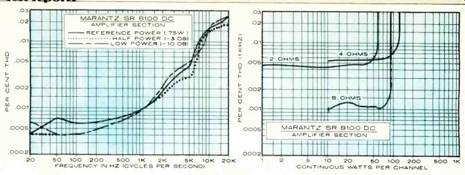
Laboratory Measurements. Following the usual preconditioning period (during which the top of the receiver became quite hot), the 1,000-Hz output clipped at 90 watts per channel into 8 ohms, 124.3 watts into 4 ohms, and 58.3 watts into 2 ohms. The 8- and 4-ohm clipping-headroom ratings were 0.8 and 1.4 dB, respectively. Using the pulsed signal of the dynamic-power test, the clipping levels were 97.3, 163.5, and 30 watts, respectively, for the three load impedances. The 8- and 4-ohm dynamic-headroom ratings were 1.13 and 2.6 dB, respectively.
When we drove 8-ohm loads at 1,000 Hz, the distortion was about 0.001 percent from below I watt to 80 watts, where it was 0.0012 percent. Into 4 ohms, the readings were only slightly higher--in the range of 0.005 to 0.007 percent up to 100 watts and only 0.02 percent at 120 watts. The 2-ohm distortion was less than 0.005 percent up to more than 30 watts output, reaching 0.1 percent at 55 watts. Obviously the amplifier is not at its best when driving two pairs of low-impedance speakers.
Using 8-ohm loads and operating the amplifier at rated power (75 watts) and at half and one-tenth rated power, the distortion was negligible over the full audio range.
The lowest reading was 0.0004 percent at 20 Hz, and the highest was 0.024 percent at 20,000 Hz. The high-frequency inter-modulation distortion, with equal amplitudes of 19- and 20-kHz input with a peak level equal to that of a 75-watt sine wave, was at-80 dB for the third-order product (18 kHz) and-76 dB for the second-order product at 1,000 Hz.
----------------------
Comment. The Marantz SR 8100 DC is a versatile, high-quality receiver that will do all that is required of it in a competent manner, asking only that the user take the time to learn to use it properly. Although not inexpensive, it is reasonably competitive with other receivers that offer similar basic performance but with out the Marantz's extra signal-processing functions.
The audio section of the SR 8100 DC is excellent, and it is powerful enough for almost any home-listening requirements. The five-band equalizer is much more flexible than the usual tone-control arrangement, and (thanks to a comprehensive manual) all the operating controls are easy to use despite their some times unconventional functions and nomenclature.
The FM tuner of the SR 8100 DC is also a very good performer. Al though not a "super tuner" (especially in respect to its S/N performance), it is as good as the FM-tuner section of any receiver we can recall testing recently.
--------------------------
------ R.F TEST-SIGNAL INPUT IN DBF
The amplifier was stable with a reactive simulated loudspeaker load. Its slew factor was 1.7, with waveform distortion visible at 34 kHz when the amplifier was driven to rated output. Through the aux inputs, 19 millivolts (mV) drove the amplifier to a 1-watt reference output and the phono sensitivity was 0.28 mV. The respective A-weighted noise readings were -78 and -75 dB, referred to 1 watt. The phono in put overloaded at a high 235 mV at 1,000 Hz, and the equivalent readings at 20 and 20,000 Hz were 250 and 242 mV. The RIAA phono equalization was accurate within 0.5 dB overall, and it was not affected by phono-cartridge inductance.
The EQ response curves were essentially as rated in respect to the center frequencies of the controls, and each slider had a maximum adjustment range of +10,-8 dB.
The loudness contours boosted both low and high frequencies as the volume setting was reduced, but the maximum boost was only about 10 dB and the sound never became objectionably heavy. The filters had not very effective gradual slopes of 6 dB per octave, with their-3-dB points being 100 and 5,000 Hz.
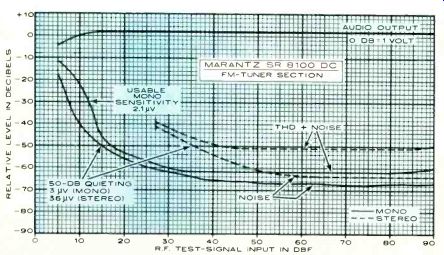
The FM-tuner section of the SR 8100 DC had a usable sensitivity of 11.8 dBf (2.1 microvolts, or µV) in mono. The stereo sensitivity was determined by the switching threshold of 27 dBf (12 µV). The mono and stereo 50-dB quieting sensitivities were 15 dBf (3 µV) and 36 dBf (36 µV), respectively. The tuner distortion at 65 dBf (1,000 µV) input was 0.073 percent in mono and 0.28 percent in stereo. The noise level at that input was-67 dB in mono and-64 dB in stereo. The mono IHF intermodulation distortion of the FM tuner (with 14-and 15-kHz tones at an equivalent 100 percent modulation level) was-56 dB for third-order (at 13 and 16 kHz) and-65 dB for second-order distortion at 1,000 Hz. In stereo, these were -49 and -55 dB, respectively, and there were the usual large number of spurious products between -65 and -80 dB.
The FM-tuner frequency response was down 1.4 dB at 30 Hz and up 1.1 dB at 15,000 Hz relative to the 1,000-Hz level.
The channel separation was excellent, aver aging 58 to 59 dB from 80 to 400 Hz and falling to 45 dB at 30 Hz and 37 dB at 15,000 Hz. Other tuner-performance measurements include a capture ratio of 1 dB (very good), AM rejection of 66 dB at 45 dBf (100 µV) input, and image rejection of 78 dB. The alternate- and adjacent-channel selectivity readings were 74 and 4.6 dB, respectively. The muting and stereo thresh olds were identical, 39 dBf (50 µV) for the Hi setting and 27 dBf (12 µV) for the Do setting. The 19-kHz pilot carrier leakage was-62 dB, and the tuner hum was-67 dB. The AM section was no better than ad equate with a frequency response of -6 dB at 80 and 3,200 Hz.
================
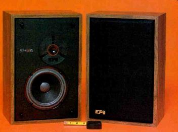
EPI A70 Speaker System
Size: 16 x 10 1/2 x 7 1/4 inches; Weight: 15 pounds; Price: $178 per pair.
THE EPI A70 is a small and inexpensive two-way "mini-bookshelf speaker system. It has a 6-inch acoustic-suspension woofer crossing over at 1,800 Hz to a 1-inch inverted-dome tweeter (similar to the tweeters used in other EPI speakers for many years). The nominal system impedance is 4 ohms, and it is rated to handle 50 watts input for 8 hours in accordance with EIA Standard RS-426A. The recommended minimum amplifier power is 15 watts per channel.
The A70 has no level or balance controls.
The insulated spring-loaded input connectors are recessed into the rear of the cabinet. Removing the black grille–cloth assembly (whose frame is retained by plastic pegs on the cabinet) reveals the drivers, with the tweeter just above the woofer and slightly to its right. The wooden cabinet is veneered in wood-grain vinyl.
Laboratory Measurements. The room-response measurements were made with the two A70 units placed against a wall at ear level for a seated listener. The microphone was about 12 feet from the left speaker (on its forward axis) and about 30 degrees off the axis of the right speaker. The signal was a sine wave sweeping from 20 to 20,000 Hz with a 0.2-octave warble.
The responses of the left and right speakers were plotted separately on the same graph and averaged to obtain a single room-response curve corrected for room absorption above 10,000 Hz. The A70 was some what unusual in its excellent dispersion at the highest frequencies (there was little difference between the two curves above 7,000 Hz), but there was a substantial difference--as much as 5 dB between the levels we measured from the left and right speakers from about 1,800 to 5,000 Hz.
The response of the woofer was measured from 20 up to about 2,000 Hz with a close-spaced microphone. This gives essentially the anechoic response of the woofer, which was exceptionally flat over most of its operating range. The woofer response was with in ± 1 dB from 70 to 800 1-17, falling at 12 dB per octave at lower frequencies. It had a dip in output of about 3 dB between 1,100 and 1,200 Hz and a return to the average midrange level before the output fell rapidly above 1,800 Hz (due to the action of the crossover network).
The composite response curve formed by splicing the woofer curve to the averaged room-response curve was flat within ± 3.5 dB from 45 to 20,000 Hz, a very creditable achievement for a small, inexpensive speaker such as the A70.
The quasi-anechoic response was measured with our IQS FFT (Fast Fourier Transform) analysis system at a 1-meter microphone distance and also at 12 inches, since a response curve taken at that distance was supplied to us by EPI and we were interested in any possible correlation between the two sets of measurements.
The measurement at 1 meter yielded a response within +6,-3 dB from 180 to 18,000 Hz (the measurement limits). Since it did not take into account the energy-
radiation patterns throughout the entire room, which had contributed to our room-response curve, it could not be expected to duplicate the latter. There were some recognizable similarities between our curves and EPI's, but they could not be called a close match.
The close-spaced (12-inch) measurement was quite similar in its details to the one we made at 1 meter. However, the phase-shift and group-delay measurements at 12 inches were much better than those made at I me ter. The group delay (a measure of the time coherence of the speaker's output) varied only about 0.3 millisecond over most of the tweeter's operating range above approximately 2,000 Hz.
The IQS computer-analysis system allows us to measure and print out the difference between two frequency-response curves as well as the actual response curve itself. When one measurement is made on the speaker's axis and the speaker is then rotated 45 degrees for the other curve, the difference between the two is a good measure of the directivity of the speaker in the horizontal plane. The two curves were with in 6 dB of each other (except for two narrow peaks at 16 and 17 kHz) over the speaker's operating range.
The low-frequency (woofer) distortion was measured with the same close micro phone spacing used for the frequency-response measurement. The speaker was driven with a 2-volt input at frequencies from 100 Hz down and also at 6.32 volts (the two levels correspond to power inputs of 1 and 10 watts to the 4-ohm rated impedance). At 1 watt the distortion was less than 1 percent down to 85 Hz, rising steadily to 6.3 percent at 40 Hz, where we stopped the measurement. At 10 watts input the distortion (as would be expected in a small speaker system) was much greater, rising from 1.4 percent at 100 Hz to 10 percent at 60 Hz and 28 percent at 40 Hz.
The speaker's impedance was rated correctly, with the minimum reading of 4 ohms occurring at 20 Hz and between 150 and 300 Hz. Elsewhere it remained well above that value, and at the bass-resonance frequency of 65 Hz it rose to about 50 ohms.
The sensitivity of the A70 was unusually high, with a sound-pressure level of 94 dB being measured at 1 meter when the speaker was driven with 2.83 volts of pink noise in an octave band centered at 1,000 Hz (this corresponds to 2 watts of power input to the speaker).
--------------
Comment. The EPI A70 sounds every bit as good as its curves suggest.
Its smoothness and good dispersion compensate to a considerable degree for its limited bass capability. It does not sound "thin" or shrill, although it cannot deliver a "gut-thumping" bass. The bass it does emit sounds surprisingly clean.
Although the size and price of the A70 might tempt some people to drive more than one pair from a single amplifier (to supply music to two rooms, for example), we would suggest caution in this respect. The A70 is a true 4-ohm speaker, and paralleling two of them will load the amplifier with 2 ohms in a frequency range where high program levels are likely to be encountered. Some amplifiers will not take kindly to this treatment, and that fact should be considered before a system is set up in this way.
The high sensitivity of the A70 should make it a logical choice for a system based on a good low-power receiver or amplifier in the 20-watt range. It can handle much higher power inputs (we used a 200-watt amplifier without dam age), but the sound quality suffers if it is pushed too hard. The A70 is not meant to fill a hall or a large, well-upholstered living room with sound at "natural" levels. It is designed to deliver a comfort able level of clean, balanced, musical sound in a relatively small room, and it does that very well and inexpensively.
==============
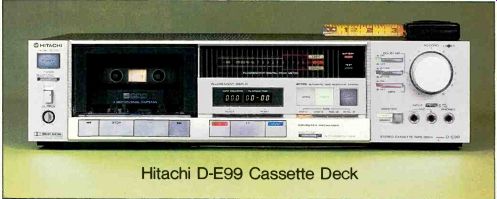
Hitachi D-E99 Cassette Deck
Size: 17.25 x 11.5x 4.25 inches; Weight: 14 pounds; Price: $569.95
THE Hitachi D-E99 is a three-head cassette deck with microprocessor-con trolled adjustment for record bias, equalization, and tape sensitivity. It incorporates both Dolby-B and Dolby-C noise-reduction systems and uses a solenoid-operated twin-capstan drive system with one motor for the capstans and a second for the reel hubs. Its separate record and playback heads (which permit direct comparison of the input signal and the recorded result) are made of high-density ferrite and are contained within a single casing.
------------- FREQUENCY IN HZ (CYCLES PER SECOND)
Cassettes are inserted, tape openings down, into slides behind the door of the illuminated cassette well. The digital tape counter reads out in conventional units (in all modes) and directly in elapsed time (minutes and seconds) for record and play back. The sixteen-segment peak-reading fluorescent level indicators, calibrated from-30 to +8 dB, had no Dolby-level marking on the scale, but both registered-1 dB when tested with a Teac MTT- 150A Dolby-level calibration cassette.
The PLAY, RECORD, and PAUSE touch but tons have illuminated LEDs, as do the four tape-type (ferric, CrO2 equivalent, ferri-chrome, and metal) selectors, the Dolby-system switches, the TAPE/SOURCE monitor and multiplex-filter switches, and the but-tons that select either fixed (factory-set) or ATRS (Automatic Tape Response System) bias/equalization/sensitivity adjustments.
The ATRS procedure takes approximately 10 seconds to complete (its operation is signaled by a flashing LED), and at its conclusion it rewinds the tape and stores the proper settings for that cassette type in its memory. The memory is retained by batteries when the unit is turned off; their condition (they should last about a year) is indicated by another LED.
Additional switches are provided for automatic rewind to stop or play, operation 13) an external timer, and for selection between microphone or line-level sources. The re cord-level controls are concentric, allowing separate settings for the left and right channels, and an output-level control is provided that simultaneously affects the output from the front-panel headphone jack and the normal rear-mounted outputs.
In addition to the regular line-level inputs and outputs, the rear panel of the Hitachi D-E99 contains a DIN-type jack for a re mote-control accessory and an access door for battery replacement.
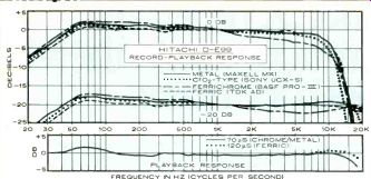
Laboratory Measurements. The factory settings for bias, record equalization, and sensitivity were made with Hitachi-brand tapes that were not supplied, so I used the ATRS system on a number of cassettes of each type. The flattest frequency response was obtained with TDK AD (ferric), Sony UCX-S (CrO2-equivalent), BASF Professional III (ferrichrome), and Maxell MX (metal) as shown in the graph, but nearly identical results were obtained (because of the ATRS system) with a wide variety of cassettes from TDK, BASF, Maxell, Scotch, Memorex, Sony, Fuji, and Loran.
Playback frequency response was measured with IEC-standard BASF calibrated test tapes, and it was exceptionally flat at the 120-microsecond (ferric) position from Hitachi D-E99 Cassette Deck.
Comment. Sonically as well as visually, the Hitachi D-E99 was a fine performer, imposing only the slightest audible high-frequency loss even with high-level inputs of interstation FM hiss (a severe test). No audible wow-and-flutter was perceptible, and there was no increase in tape background noise at any tolerable listening level when using the Dolby-C system. The Dolby-B and Dolby-C noise-reduction systems both tracked the basic deck frequency response within ± 2 dB, and the FM multiplex filter was admirably sharp in its response. In short, I found the Hitachi D-E99 to be a very good deck that is worthy of consideration by any audiophile.-Craig Stark 31.5 Hz to 18 kHz. There was a mild rolloff (3.5 dB) at 18 kHz in the 70-microsecond (CrO2) position. At the normal -20-dB in put level the overall record-playback response was within ±3 dB from approximately 40 Hz to 20 kHz, though a 6-dB-per-octave bass rolloff was imposed on frequencies below 50 Hz. Interestingly, the response of TDK AD (ferric) essentially matched that of the metal Maxell MX at both -20- and 0-dB input levels.
With a 0-dB input level at 315 Hz, the third-harmonic distortion levels measured 0.43 percent (TDK AD), 0.82 percent (Sony UCX-S), 1.1 percent (BASF Professional III), and 1.5 percent (Maxell MX).
It took an additional input of 4.7, 5.2, 2.4, and 2.3 dB for the four tapes, respectively, to reach the 3 percent third-harmonic distortion level. Unweighted signal-to-noise ratios (S/N), without noise reduction, measured 59.7, 58, 58.7, and 54 dB, respectively. With Dolby-B and IEC-A weighting, S/N improved to 70.5, 69.3, 70.3, and 66 dB; with Dolby-C, using the CCIR weighting, S/N measured 80.5, 74.7, 79.8, and 72 dB, respectively.
Wow-and-flutter, using a Teac MTT-III test tape, measured 0.024 percent wrms and 0.038 percent with the DIN peak-weighted standard. Line-level input sensitivity for a 0-dB indication was 0.13 volt, with an output of 0.5 volt. Using a 600-ohm generator, microphone input sensitivity was 0.5 mV, and overload occurred at 120 mV. Fast-winding time for a C-60 cassette was an average 64 seconds.
================
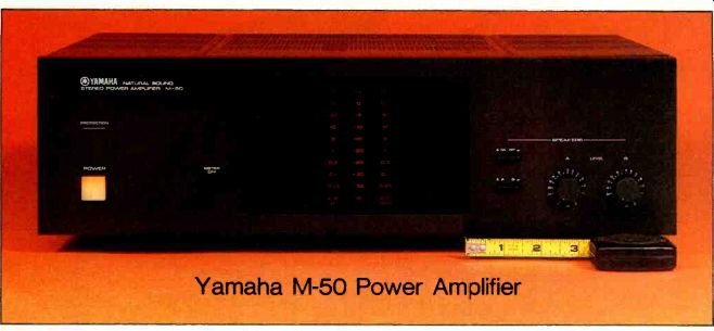
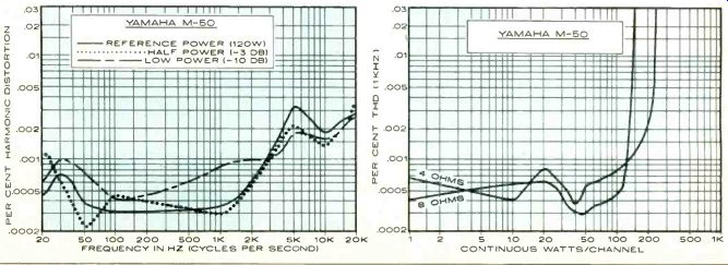
Yamaha M-50 Power Amplifier
Power Rating: 120 watts per channel; Size: 17 1/4 x 5 1/4 x 15 inches; Weight: 26 pounds; Price: $650
THE Yamaha M-50 power amplifier features the company's ZDR (zero distortion rule) amplifier circuit and the "signal-tracking" X power supply that is intended to provide higher overall operating efficiency. Also in the interest of low distortion, Yamaha employs a "linear-transfer bias circuit" in the output stages to virtually eliminate crossover distortion. Although no circuit details are given, the block diagram of the amplifier suggests that the ZDR feature is a form of amplified feedback of the extracted distortion signal.
The performance specifications of the Yamaha M-50 include a 120-watt output into 8-ohm loads from 20 to 20,000 Hz with no more than 0.002 percent total harmonic distortion. With 4-ohm loads, the only specification is a clipping output of 200 watts per channel, and there is no rating for any other load impedance. The M-50 is finished entirely in black. The front panel contains a large square illuminated pushbutton power switch, and a PROTECTION light comes on if the amplifier's protective circuits operate for any reason (they delay the connection of the speakers for a few seconds when the amplifier is turned on to prevent turn-on transients from reaching the speakers).
At the right side of the panel there are separate level controls for the two sets of speaker outputs, either (but not both) of which can be selected by a button near the level controls. Another button shuts off the speakers entirely. Although the two controls (marked A and B) resemble the individual channel-level controls sometimes used on power amplifiers, each of them affects both channels equally for the selected speaker output.
A large rectangular window in the center of the panel contains a dual peak-power display. In it are two vertical columns of short horizontal bars that light in orange to follow the instantaneous output level of their respective channels. Each column is calibrated in power output (based on 8-ohm loads) from 0.03 to 150 watts, with a row of corresponding decibel calibrations in the center of the display. A small button to the left of the window shuts off the display. On the rear apron of the M-50 there are insulated speaker connectors, the input phono jacks, and a single unswitched a.c. outlet.
--------- FREQUENCY IN HZ (CYCLES PER SECOND) CONTINUOUS WATTS/CHANNEL
The speaker connectors, which resemble conventional binding posts, have holes that accept the stripped ends of the wires; a quarter-turn of the connector clamps the wire firmly in place and makes a solid electrical connection.
Laboratory Measurements. The 1-hour preconditioning of the Yamaha M-50 at an output of 40 watts into 8 ohms, followed by five minutes of full power, resulted in a rather hot top cover above the transistor heat sinks. The power output at clipping (1,000 Hz into 8 ohms) was 153 watts per channel for a clipping-headroom rating of 1.06 dB. With 4-ohm loads, the clipping power was 240 watts, well above the 200-watt rating. We could not make any measurements with 2-ohm loads since the protective circuit shut off the amplifier outputs before the waveform clipped. The dynamic-power output was measured with the 20-millisecond tone bursts of the standard IHF test, with the outputs clipping at 156 and 260 watts into 8- and 4-ohm loads, respectively. The 8-ohm dynamic-headroom rating was about average at 1.14 dB. When we tried to drive 2-ohm loads with the pulsed signal, we found that the waveform distorted (rounded off symmetrically) long be fore the protective system operated. The maximum reasonably undistorted output into a 2-ohm load was roughly 20 watts per channel.
Nevertheless, Yamaha's claims to ultra-low distortion were essentially confirmed with 8-ohm operation. At 1,000 Hz, the distortion was between 0.0003 and 0.001 percent from 1 watt to at least 120 watts output (with 4 ohms the results were quite similar, the 0.001 percent point being about 140 watts per channel). At rated power or less, the 8-ohm distortion was between 0.0003 and 0.001 percent from 20 to 3,000 Hz, rising to a low maximum of about 0.003 percent in the 5,000- to 20,000-Hz range.
The high-frequency linearity was also measured with the two-tone IHF intermodulation-distortion test signal consisting of equal amplitudes of 18- and 19-kHz signals whose peak amplitude was equal to that of a 120-watt sine-wave output. The second-or der (difference-tone) distortion at 1,000 Hz was an excellent-90 dB, and the third-or der (17-kHz) component was -64 dB, both referred to 120 watts.
The sensitivity of the Yamaha M-50 for a reference output of 1 watt was 0.105 volt, and the A-weighted noise in the output was less than our 100-microvolt measurement limit (better than 90 dB below 1 watt). The amplifier's slew factor was greater than 25, and its rise time was 3 microseconds. It was stable with reactive simulated loudspeaker loads, and its IHF reactive-load rating was 1.18 dB.
---------
Comment. In service as part of a home music system, the Yamaha M-50 worked perfectly, with absolutely no sound of its own. Even turn-on and turn off operations were completely silent. It delivered the type of performance we would expect from such a deluxe audio component. Recalling its limited output with low load impedances, we paralleled several pairs of speakers in an effort to hear distortion when the amplifier was driven hard. In this we were only partly successful. Distortion was audible only when we drove the M-50 very hard, producing sound levels far beyond what any rational person would find enjoyable in a home environment. While the distortion disappeared when we switched to a much more powerful amplifier that was able to drive low-impedance loads with out difficulty, this is hardly a fair com parison with the M-50.
Yamaha's awareness of the current-output limitations of the M-50 is demonstrated by their using an output-switching system that makes it impossible to drive two pairs of speakers simultaneously regardless of their impedance ratings. The apparently unruffled behavior of the amplifier when we drove a group of speakers whose combined nominal impedance must have been less than 2 ohms can probably be explained by the fact that actual speaker impedances vary widely with frequency, and no two are likely to be alike in this respect. t is therefore probable that the amplifier never "saw" an impedance as low as 2 ohms; at most frequencies it may have been closer to 4 or 5 ohms. Combined with the frequency distribution of most music, it is not hard to understand why the apparent deficiency on the test bench might have been of little practical importance. However, there are speakers whose actual impedance comes perilously close to 2 ohms at some frequencies, so caution is advisable when using them with this amplifier.
One surprising discovery about the M 50 was that it is not a particularly cool-running amplifier despite its "X" power supply. Even operating with no signal, its top became distinctly warm-not actually hot, but certainly not as cool as even some conventional amplifiers of the same or higher power ratings. It is also not especially small or light for an amplifier of its power rating, although it must be admitted that there are heavier and larger "120-watt" amplifiers on the market. The M-50 is a good amplifier, with extremely low distortion and no vices other than those already mentioned. It is not inexpensive, but it appears to be well built and adequately protected.
----------------
Also see:
Link | HOW TO HANDLE RECORDS--From jacket to turntable and back without dust or damage.