The following video disc system and circuit operations are used in the new Magnavox disc players.
MAGNAVOX MODEL VH8000 VIDEO DISC PLAYER
A video disc is composed of thousands of circular "tracks" made of a continuous spiral from the inside of the video disc to the outside. These tracks are analogous to grooves in an ordinary audio record. The tracks of a video disc, however are not grooves. They consist of microscopic "pits" which are minute indentations in the video disc material. Figure 11-1 shows the width of a single track, as well as the track pitch or space between tracks. Note that the dimensions are given in microns. A micron is one millionth of a meter. The length of the pits and the spacing between the pits determines the intelligence on the video disc.
A cross section of one side of a video disc is shown in Fig. 11-2. First the pits are pressed into a transparent plastic base material.
Next, a thin reflective layer of aluminum is added and a protective coating is placed over the aluminum layer. Finally, two sides are sandwiched together to form a double sided disc. The light beam penetrates the plastic base material on the bottom and focuses onto the surface of the aluminum coating. Light reflected from inside a pit is less bright than light reflected from the spaces between the pits. Thus, intensity modulation of the light beam is achieved as the video disc rotates. The intelligence encoded on the video disc is the resultant of the following three FM signals.
8.1 MHz FM modulated with composite video (including chroma). 2.3 MHz FM modulated with channel 1 sound.
2.8 MHz FM modulated with channel 2 sound.
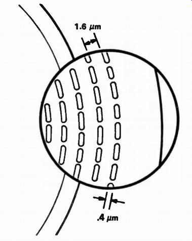
Fig. 11-1. Magnified view of a video disc track.
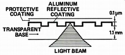
Fig. 11-2. Cross section of one side of a video disc.
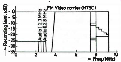
Fig. 11-3. Frequency spectrum of videodisc information.
Fig. 11-4. Encoding of disc information.
Referring to Fig. 11-3 we can see these three signals in the frequency spectrum. Each of the sound carriers has a maximum deviation of ± 100 kHz. The 8.1 MHz video FM carrier has a deviation of 1.7 MHz (sync tip to peak white); however, its bandpass extends below 4 MHz to up above 12 MHz in order to include all necessary sidebands. Each of the sound FM signals pulse width modulates the 8 MHz video to create the actual resultant signal that becomes encoded on the video disc.
Figure 11-4 is a simplified drawing of one of the sound carriers (B) being used to pulse width modulate the 8 MHz video FM (A). The resultant signal (C) is clipped and used to create the pits (D) in the video disc. Note that waveform (C) can cause the length of the pits and the spacing between the pits to vary.
Each revolution of a standard play video disc causes one TV frame to appear on the TV screen. One TV frame consists of two interlacing fields, thus, the screen is scanned from top to bottom twice during one revolution of the video disc. One half of the video disc is the first field and the other half is the second field. The fields are separated by vertical sync and blanking sections on the video disc. Note that the vertical field track length varies from one location on the disc to another. This arrangement of the vertical fields, sync, and blanking holds true during the entire time the disc plays from the inside to the outside. Standard play video discs rotate at a constant 1800 RPM which is 30 Hz, the TV frame rate. It is these features of the standard play disc that allows the special modes of operation (still, slow motion, etc.) to be performed.
The illustrations in Fig. 11-5 show how the standard play and extended play video disc layouts compare.
FUNDAMENTAL VIDEO DISC OPERATION
Tracking of the light beam is very important as you will see when we delve into the operation of the blocks of the overall system. Two types of tracking are involved in this video disc player:
• Radial tracking.
• Tangential tracking.
Radial tracking simply means keeping the light beam centered on the track. Otherwise, the beam may drift between tracks and the picture would be lost or distorted. Radial movement of the beam is always perpendicular to the tracks.
Tangential tracking always moves the beam in line with the track.
This direction of movement is necessary to compensate for any momentary speed errors of the track passing over the beam.
The fundamental block diagram will be found in Fig. 11-6. Located at the center of the system is the slide assembly. The slide assembly contains the laser and an the optics for the system. The slide drive motor moves the entire slide assembly beneath the video disc as the program is played.
The laser generates a red light beam which passes through an optical divider. The beam is then deflected by the automatic tracking mirrors up into the objective lens. This lens focuses the beam into a tiny point on the bottom of the video disc.
The reflected beam follows the identical path through the objective lens and the automatic tracking mirrors to the optical divider. The reflected beam is then separated from the original beam and sent to the light sensitive diodes (also called the photo diodes). The diodes conduct a varying current dependent upon how much light falls on them. Since the reflected beam is intensity modulated by the pits on the video disc, the diodes create the FM signal which was recorded on the video disc.
The light sensitive diodes also create a focus error voltage if the video disc should get too close or too far from the objective lens. The objective lens can move up and down to follow up and down movements of the video disc and thus always maintain correct focus. The focus error voltage is applied to the focus servo which controls the objective lens movement. A servo is simply a high gain amplifier in a closed loop configuration used to control mechanical movement.
Thus the heart of the video disc player is the laser and optical components. Just a few of the many circuits will now be covered on the video disc player.
LASER DRIVE CIRCUIT OPERATION
The laser is essentially a gas filled vacuum tube with an anode and a cathode. It is in the shape of a long glass tube with a mirror on the inside of each end. Operation of the tube is analogous to that of a thyraton. That is, a certain "firing" voltage must be applied between anode and cathode to make the gas ionize and cause current flow. Once the tube has fired (ignited), less voltage is required to maintain the current flow.
Helium and neon gas is used in this laser. When it ionizes it emits red light. The light reflects back and forth between the mirrored ends, continually gaining power. One of the mirrored ends is only partially reflective. The light penetrates that mirror and exits the tube as a laser beam.
The optical power of the laser output is only 1.2 mw. It is not dangerous for the beam to strike the skin. The beam will not even harm a piece of tissue paper. However, the beam should not be allowed to travel directly into the eye. For this reason the player is designed to turn off the laser instantly whenever the lid is raised. In addition, the light path is mechanically blocked as the disc lid is raised.
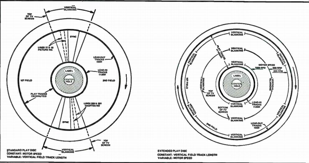
Fig. 11-5. Comparison of video discs.
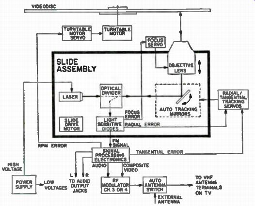
Fig. 11-6. Block diagram of disc player.
LASER POWER SUPPLY CIRCUIT
Figure 11-7 shows the DC power supply for the laser. It is driven by a secondary winding of the power transformer, Ti. Diodes D7 and D8 are voltage doublers. During positive excursions of the driving sine wave, D8 conducts and charges C11, C10 and C9 to about 900 volts DC. During the negative half, D7 conducts and charges C6, C7 and C8 to about 900 volts DC. The polarities are additive so the resultant voltage across all the capacitors will be 1800 volts DC. The resistors in parallel are 1 meg ohm.
These equalize the voltage across each capacitor and discharge the capacitors when the power is turned off. C21 acts as a surge suppressor across the secondary winding, while C3 and R17 serve as a high pass filter to eliminate high frequency noise which might get into the power supply.
The Laser and its HV power transformer are shown in the Fig. 11-8 circuit. The laser HV transformer looks like a HV triple found in some color TV sets. This HV unit is mounted on the slide assembly with the laser. The circuit is a series circuit with the 1800 volt source supplying current through the regulator circuit (Fig. 11-9) and then through the laser and laser transformer to ground. Note that neither side of the 1800 volt supply is connected to ground. The cathode lead from the laser passes through the laser transformer, yet no connections are made to it and this is done for safety reasons.
The 1800 volts will not turn on the laser. A multivibrator circuit is used to drive the primary of the HV transformer Ti. The transformer output is around 10 KV. Diode D1 rectifies this voltage and C1 charges up to about 10 KV. When this HV is felt across the anode and cathode of the laser, the laser turns on and C1 dumps its energy through the laser and R1 to provide the initial turn on current.
As soon as 5 ma flows through the laser, the regulator circuitry turns off the multivibrator and the 10 KV disappears. The laser only requires about 1200 volts to maintain the 5 ma of conduction. Thus, the 1800 volts source can keep the laser on once it is conducting. The remaining 600 volt level varies widely from below 100 volts to over 800 volts depending on the line voltage, laser current, etc. During normal conduction of the laser, the secondary winding of the HV transformer, Ti has too much resistance to allow sufficient DC current flow. D2 shunts this winding and the 5 ma current flows through D2 instead of D1 and Ti.
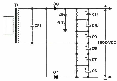
Fig. 11-7. Laser power supply circuit.
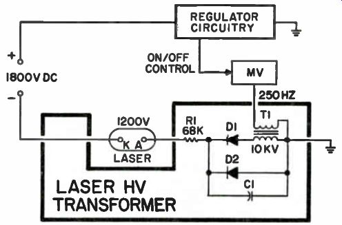
Fig. 11-8. Laser and High Voltage transformer.
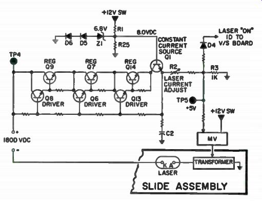
Fig. 11-9. Laser supply regulator circuit.
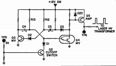
Fig. 11-10. Laser multivibrator circuit.
LASER MULTIVIBRATOR CIRCUIT
The multivibrator circuit that drives the laser transformer is shown in Fig. 11-10. The multivibrator is the free running type and consists of Q3 and Q4. When the lid is closed, the 12 volt switched source appears and switches Q4 on through R13. The collector of Q4 goes near ground potential and C5 begins to charge toward 12 volts. When the C5 voltage reaches about 1.2 volts, D2 and Q3 switch on. The collector of Q3 goes near ground potential and turns off Q4 through C4. C4 begins to charge toward 12 volts. When the C4 voltage reaches about 1.2 volts, Q4 switches back on and the process repeats itself.
The result is a 250 Hz square wave that drives the base of amplifier, Q5. Q5 is a high current amplifier used to drive the step-up transformer.
The resultant driving waveform can be monitored at TP6, but is only present for a brief instant during turn-on of the player. As soon as the laser fires, 5 volts is present at TP5 and turns on Q2. Q2 shorts the base of Q4 to ground through D1. Thus, Q4 is disabled and the multivibrator cannot run.
Q4 is a Darlington because of the high gain required to drive Q5. D2 creates a two junction turn-on requirement for Q3 to balance it with the two junction turn-on requirement of Q4. D3 and D20 are protection diodes to prevent positive voltage spikes at TP6 from damaging components or upsetting circuit operations.
SIGNAL PROCESSING
The photo diodes and the pre-amp module are located on the slide assembly. Note block diagram in Fig. 11-11. The preamp provides reverse bias to all diodes. Diodes A, B, C, and D are applied to a summing circuit where (A+B) and (C+D) are created. These pairs are applied to another summer and amplifier to create the total FM signal (A+B) + (C+D). The pairs are also subtracted in a difference circuit to create the focus error voltage, (A+B) - (C+D). The outputs of photo diodes E and F are applied to a difference amp which creates the true radial error voltage. This voltage is high frequency emphasized to make another radial error voltage called radial error with high frequency compensation. The use of these focus and radial error voltages will not be covered at this time.
A simple block diagram of the signal processing circuitry is shown in Fig. 11-12. The total FM signal from the pre-amp on the slide assembly is applied to the high frequency amp/splitter. Frequency sensitive networks separate the sound FM from the video FM. The sound FM is applied to two frequency sensitive stages the 2.8 MHz sound two demodulator and the 2.3 MHz sound one demodulator.
These stages serve as FM detectors and retrieve the audio signals from their respective carriers. The two resulting audio nZ16h6s are fed to an electronic switch network which applies either one or both of the signals to the VHF modulator.
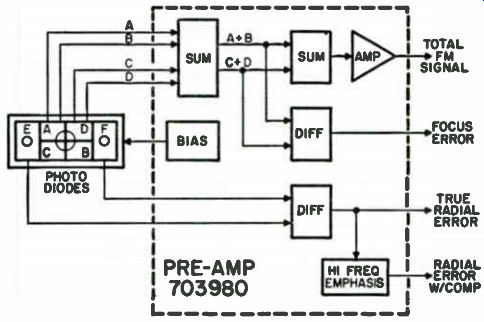
Fig. 11-11. Photo diodes and pre-amp module.
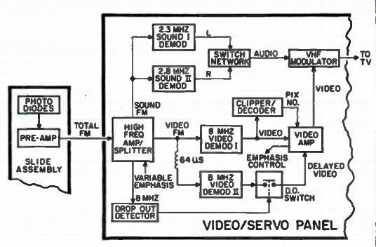
Fig.11-12. Signal-processing block diagram.
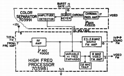
Fig.11-13. FM signal processing circuit.
The 8 MHz video FM is applied to video demodulator one which extracts the composite video signal from the carrier. The composite video signal is amplified by the video amp and applied to the VHF modulator. The picture number digital logic is clipped from the composite video signal by the clipper/decoder circuit. Here the logic is decoded and converted to the picture number video signal. The signal is also amplified by the video amp and fed to VHF modulator. The VHF modulator places the audio and video onto the required RF frequencies for channel 3 or 4. The resultant RF signal is fed to the TV set via the antenna switch box.
The video circuitry creates a DC voltage proportional to burst amplitude. This voltage is called emphasis control because it is applied to the high frequency amp to emphasize the high frequencies when operating near the inner diameter of the video disc. The high frequency emphasis effect decreases as the program progresses toward the outer diameter.
This control is required due to the pits being more closely spaced at the inner diameter and thus resulting in less high frequency response.
The player is designed to compensate for minor "dropouts" of intelligence from the video disc. A drop out is an area on the video disc which has incorrect encoding or no encoding. This loss could be caused by physical damage to the video disc. The dropout correction circuitry can compensate for the loss of up to one complete horizontal line on the TV screen.
The 8 MHz video FM signal is fed to the dropout detector circuit. If a bad spot on the video disc is found the 8 MHz signal will be absent and the dropout detector will sense this absence. The 8 MHz signal is also applied through the 64 microsecond delay line (one horizontal line period) to the video demodulator two. When a dropout is found, the dropout detector activates the electronic dropout switch which applies the previous horizontal line in place of the one that was dropped out. The result on the screen is two horizontal scan lines with the same video information. Thus, the dropout has been "filled in" by repeating the previous line.
Now let's take a closer look and see how this signal processing job is accomplished with the various modules in the system. With the exception of the pre-amp module on the slide assembly, all signal processing is located on the video/servo board. The total FM signal from the pre-amp module is applied to the high frequency processor module, as shown in Fig. 11-13. The RF amp amplifies the entire signal. The gain control, R3002, is used to set the correct amplitude output.
The output of the RF Amp is applied to the input of the sound FM Amp. The input is tuned and passes only the 2.3 1V1Hz and 2.8 MHz sound carriers. Both amplified sound carriers are present at pin 15.
The high frequency portion of the RF signal obtained from the video disc has less amplitude at the inside of the video disc than at the outer diameters. The variable high frequency emphasis network is used to level out the high frequency response over the entire video disc. The circuit is controlled by a DC voltage at pin 1. This control voltage is proportional to the 3.58 MHz burst amplitude of the composite video signal. The color separator module removes the burst from the video signal by keying the burst separator with the horizontal rate burst gate pulse at pin 15. The amplitude detector creates a DC voltage proportional to the burst amplitude.
As the DC voltage at pin 1 decreases, the high frequency response increases. The net effect is to boost the high frequency at the inside on the video disc. The video FM amp, amplifies the 8 MHz video FM signal and feeds it to pin 3 of the module. The 2.8 MHz trap removes any remaining channel 11 sound carrier at this point. Remaining 2.3 MHz will be trapped out later.