The number of transistor types now in use makes it virtually impossible to stock all the original type numbers. Even stocking a portion of them ties up considerable capital in transistors that might or might not be needed.
Not too long ago, when germaniums were the only kind of transistors used, several manufacturers marketed eight to ten replacement units that would fill 90 percent of the replacement needs. Today, with silicons added to the replacement lists, 30 general replacement types are needed to fill the majority of requirements. Whether you use the suggested replacements cross-referenced by several manufacturers, or whether you categorize your own replacement types, the information in this article should make selection of transistor replacements less of a guessing game.
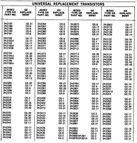
Fig. 1 Shown here are portions of two cross-reference charts published by
manufacturers (RCA and GE).
PNP or NPN
How can you be sure you are selecting the right replacement? The simple and most practical way is to check manufacturers' cross-reference charts, like the ones shown in Fig. 1. Find the original transistor type number and then check for the replacement recommended.
If the replacement guide is not available, or if you cannot tell what the original part number was, then you will need to find out as much as you can about the characteristics of the original. First, is it an NPN or PNP? If you have the schematic, you can determine this by the direction of the emitter arrow; as shown in Fig. 2, if the arrow is pointing "out", it is an NPN, and if pointing "in", a PNP. (Some technicians remember this by using this little saying: PNP for "Pointing 'N Proper" and NPN for "Not Pointing 'N".) A second method of checking the type (it's possible for the draftsman to draw the arrow wrong, or you might not have a schematic) is to determine the polarity of the collector-to-emitter voltage. If the collector is negative relative to the emitter (not necessarily to ground), the transistor is a PNP. If the collector is positive to the emitter, the transistor is an NPN (Fig. 3). You can remember which polarity is which by recalling that the middle letter of the type designation indicates the collector to emitter polarity-negative for PNP and positive for NPN.
Is It Germanium or Silicon?
If the type number is lost, or you have no cross-reference information, the best way to determine whether a transistor is a silicon or germanium is by the amount of base-to-emitter bias. The bias for a germanium type will be 0.2 volt or less, while the silicon will have a bias of 0.4 volt or more. (This will not hold true always, because certain circuits, such as sync clippers or oscillators, can have little or no DC bias, or they might even have reverse bias when operating normally.) The above information should be obtained from the schematic (as in Fig. 4), because you won't be able to take an accurate bias reading if the transistor is defective. Usually, though, you can expect all transistors in a particular design to be either germanium or silicon, especially if they are in the same type case. In this event, you can measure the bias on other transistors to determine how much bias to expect on the defective one. But even here there are pitfalls, because in a DC coupled circuit, the bias on all transistors will be changed when one transistor fails.
Another way to determine whether the transistor is germanium or silicon is the design of the circuit itself. (Again, this is not absolute, but at least it is a good clue.) For example, which one of the circuits in Fig. 5 almost surely uses a silicon transistor? silicons?
The answer is B, be cause there is no emitter resistor.
Only a silicon, with its excellent stability, can be operated safely without a protective emitter resistor.
Also note that there is only one base bias resistor. This, too, is permissible in silicon transistor circuits, because of the low internal leakage of silicons, and because they have minimal change in leakage within a reasonable change in ambient temperature.
The circuit in Fig. 5A could be using a silicon transistor, but is more apt to be using a germanium. Some designers continue to use the conservative design of the germanium circuit for silicons, but these are gradually disappearing.
Selecting a Replacement
There are several manufacturers who cater to the replacement transistor market, and it seems foolhardy not to take advantage of their experience by buying the transistors which they have selected as ideal replacements, and by using their cross-reference charts.
You will find, once in a while, that a designated replacement will not take the place of the original in some particular circuit. It is almost impossible for a manufacturer to de sign a complete line of transistors that will replace every transistor in any type circuit with perfect results in all cases. You must recognize that there are a few exceptions to each of the rules that apply to placements.
The main rules that you should always obey are:
• the replacement transistor you select should be of the same general type as the original
• it should be designed to operate in the same general kind of circuit
• the collector-to-emitter voltage rating should be high enough.
For example, you should not try to replace a germanium with a silicon, nor the other way round, nor should you try to replace an NPN with a PNP. You should not replace an FM RF amplifier with an AM Mixer type, nor an IF amplifier with an AF type. (Though, in the latter case, it often is permissible to substitute in the opposite direction; that is, replace a transistor of a "lower" type with one of a "higher" type. For example, an audio amplifier transistor can be replaced with an IF amplifier type, or a low-frequency transistor can be replaced with one meant for higher frequencies.)
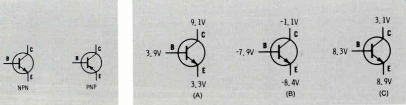
Fig. 2 The direction of the emitter arrow indicates whether the transistor
is an NPN or PNP. Other checks will verify this, as pointed out in the text.
Fig. 3 Which of the above transistor symbols is incorrect, assuming that the voltage readings are correct? The answer is C. Note that the collector is actually more negative than the emitter; this wound indicate that the transistor symbol should be a PNP, with the arrow pointing in.
What About Gain?
So many factors enter into the calculation of stage gain that the actual DC gain, as read on a tester, can be meaningless. The voltage gain is important in a voltage amplifier, yet that same transistor is not a good choice for a transformer-coupled audio driver, in which current, or power, gain is desired.
The beta (gain) of different RF amplifier transistors might vary considerably, but in some cases the one with the lower beta might actually function a little better in-circuit. For this reason, replacement transistor gain is usually not considered critical. Current gains will range around 70, but might drop to as low as 40 or so for power amplifiers, or up to 140 or 150 for some mixers, RF and IF amplifiers, especially sil icon types.
The gain of a particular transistor seldom will change during its lifetime; consequently, as long as a transistor has gain, it usually can be assumed that the indicated gain is normal. This is particularly true of silicon transistors, which seldom develop troublesome leakage. Germanium transistors sometimes develop an apparent change in gain due to a change in leakage resistance.
What About Leakage?
The maximum permissible leak age in a transistor circuit depends a great deal on the impedance of the input circuit. For example, if the DC resistance of the input circuit is 5K ohms or less, more transistor leakage can be tolerated than if the DC resistance is one megohm.
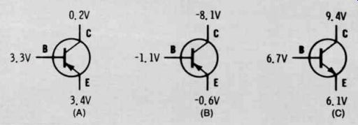
Fig. 4 Which of the above transistors The Answer: B and C., because are both
have more than 0.4 volt base-to-emitter bias.
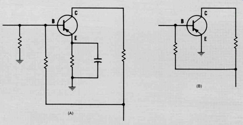
Fig. 5 Which of these circuits most likely uses a silicon transistor? The
answer is B. See text for complete explanation.
Germanium transistors, even of the same type number, have different amounts of leakage, which al ways increases as the temperature increases. On the other hand, silicon transistors normally have almost no leakage, and remain stable over a wide temperature range. As a matter of fact, silicons seldom have, or develop, any significant leakage, unless they go completely bad, in which case they become shorted, or nearly so.
Other Considerations
Four-lead transistors often are found in older high-frequency equipment, such as FM tuners or radios.
The fourth lead usually is connected from the metal case of the transistor to common, or ground, in the circuit. In most instances, a four-lead transistor can be replaced with a three-lead one, as long as it is the same general type. Connect the re placement leads to the emitter, base and collector terminals, and disregard the fourth wire connection.
Today, most new solid-state circuits use silicon transistors, and you can expect good uniformity and, thus, interchangeability among units of the same general type; for example, an NPN FM amplifier used as the replacement in one make of radio would replace, in just about every case, an NPN FM amplifier in another make radio. Consequently, if you have some exact replacements in stock, you can use them in the same stages in other makes of equipment, to help relieve stocking problems.
Take special care when replacing transistors in DC-coupled, or "stacked", circuits, such as those used in the audio amplifier stages of auto radios. Tack in the replacement temporarily, and take collector-to-emitter voltage reading of each stage to see if they correspond closely to the original readings. If they do, and the gain and fidelity is good, the replacement then can be installed permanently.
Be sure that the voltage rating (V_ceo) of a replacement transistor is at least a little above the supply voltage used for that particular stage. Be particularly careful about transient voltages, such as can occur when connecting or disconnecting a transistor while the power is turned on. Transients are one of the biggest causes of transistor failure.
Don't overload a transistor--even a temporary short can permanently damage it. Keep the current below the rated limits, or the transistor might be ruined instantly.
When installing transistors on a heat sink, be sure to install properly the necessary mica- or oxide coated washers, and insulators.
Also, always add a thin coating of a special oxide-filled silicone compound between the transistor case, the insulator and the heat sink on the chassis to improve the transfer of heat from the transistor to the heat sink. The correct type of silicon compound is available at nearly all electronic parts distributors.
Compare the lead arrangement of the replacement with the original transistor-it could be different. If it is, bend the lead wires on the requirement so that they will correctly fit the holes in the printed board without touching the other leads.
You should always recheck the alignment of any RF circuit in which you install a new transistor, even with an "exact" replacement transistor. Usually, if the replacement is suitable, you will not need to make any drastic change, but a check and touch-up is recommended to insure peak performance.
If you are not sure about a particular replacement, it's a good plan to "tack" it in before making the installation permanent. It usually is easier to tack in the replacement on the print side of the board, but be sure you have removed the original transistor. If the circuit functions as required after a check-out, install the transistor permanently on the component side of the board.
To prevent callbacks, always al low a circuit to perform normally for at least 30 minutes before re turning it to the customer.
Soldering Precautions
When soldering leads on a re placement, it's always a good idea not to apply heat for any longer than absolutely necessary, especially if the leads are short. This is because the short leads will conduct the heat into the transistor itself, r and possibly damage it. If possible, you should grasp the transistor leads with a pair of long nose pliers, which will act as a heat sink to reduce the amount of heat reaching the transistor. Unfortunately, it often is impossible to use any type of heat sink because of the crowded location of the transistor. The following tips can prevent possible trouble in any case:
• Don't let the soldering iron touch the transistor leads for more than 8 to 10 seconds, especially if the leads are a half inch or shorter.
• Leave the leads as long as feasible when soldering in the re placement. However, pay particular attention to correct lead length in UHF circuitry.
• Use a small soldering iron with a small tip.
• If possible, grip the transistor lead with a pair of long-nose pliers between the body of the transistor and the point being soldered.
------------------------