Facts all technicians need to know about series and shunt rectifier circuits. Explains how and why the shunt rectifier is the basis of most oscillators, sync separators and horizontal drive circuits. Practical methods of using a scope to diagnose rectifier circuit defects also are included.
Understanding Diodes
Only two things are necessary for rectification: a source of AC and a diode. All other parts are refinements-even a filter capacitor can be replaced by a battery in some circuits. Diodes can be vacuum-tube or solid-state types made of such materials as copper-sulfide, selenium, germanium or silicon. As sorted types of solid-state rectifiers are shown in Fig. 1. Later, we will see that the grids of tubes and the bases or collectors of transistors can function similarly to the anode of a diode.
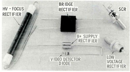
Fig. 1 An assortment of typical solid-state diode rectifiers.
Any diode is actually a voltage controlled switch, regardless of its type of construction or efficiency.
When the anode is positive, relative to the cathode, a near-perfect diode will have almost zero resistance, as shown in Fig. 2. Or, to say the same thing another way, when the diode is forward biased, the for ward resistance is nearly a short circuit. When the anode is negative, relative to the cathode, the diode is reverse biased, and a near-perfect diode will have infinite resistance.
These statements are true even when the diode is used as a DC clamp, an AM detector, a power supply rectifier or a damper.
The efficiency of any diode is measured by the power (wattage) dissipated across it as the result of both forward-bias voltage drop and reverse-bias leakage current. Let's again analyze the action of a near perfect diode: Current produced by forward bias can be very large, but the voltage drop across the di ode will be nearly zero, because the internal resistance also will be nearly zero. The formula is: Wattage = I' X R, but if R is zero, the answer also will be zero. When the diode is reverse biased, the voltage across the diode will be very high, but the leakage current will be nearly zero. Again, almost no power will be dissipated across the diode.
Perfect diodes do not exist. A tube diode can have zero reverse current, but the forward resistance is relatively high. A silicon diode might have very low forward resistance but measurable reverse current. At this time, silicon diodes have the highest efficiency of any used commercially.
All such diode losses produce heat; the less heat, the higher the efficiency. The heat generated by a diode depends, in part, on the length of time it takes to switch from a completely "on" state to a completely "off" state, or visa versa.
Between these two operating states, internal resistance is relatively high.
The quicker this switching action, the less heat generated. The ultimate in efficient switching is the conventional on-off switch. These facts explain how SCR's and triacs can switch large amounts of power and remain relatively cool. They are either completely on or completely off-the two conditions where heat dissipation is minimum.
Evolution of Rectifier Circuits
The most simple rectifier circuit, consisting of a source of voltage, a diode and a load resistor, is shown in Fig. 3A. The output waveform is produced by the positive half of the incoming sine wave, as pictured in the double-trace scope waveform in Fig. 3B. Diode conduction occurs only when the anode is positive, and because there is a pulse of positive voltage for each positive side of the sine wave, the frequency of the rectified output is 60 Hz. If you don't have a dual trace scope, check the frequency by connecting the vertical input probe pf your scope to the positive end of the load resistor, and the scope ground lead to the power supply ground. Reset the scope controls for internal 60-Hz horizontal (sine wave) sweep. Adjust the vertical and horizontal gain controls for equal height and width; the wave form should look like that of Fig. 3C, if the output of the power sup ply is a positive-going pulse. If your scope does not have internal 60-Hz horizontal sweep, change the controls for external horizontal sweep, then attach the horizontal input probe to the anode of the diode, Xl. Adjust width as needed. This kind of rectification is often called "half-wave", because only half of the sine wave is used. The DC voltage produced will be low because VOM's and VTVM's average any rapid variation in voltage, and this I half-wave voltage is present only part of the time, thus making the average very low.
"Full-wave" rectification is illustrated in the schematic of Fig. 4A. The center-tapped transformer provides 180-degree, out-of-phase voltages to X1 and X2, which causes them to conduct alternately when their anodes become positive. Comparison of the full-wave output with the sine-wave input in Fig. 4B verifies that the output pulses of the full-wave voltage are 120 Hz. Or, use the 60-Hz horizontal sine-wave deflection on your scope, as de tailed before, and the "V" wave shape (like that in Fig. 4C) will prove the output pulses (if they are positive) to be 120 Hz.
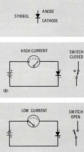
Fig. 2 A diode is a voltage-controlled switch. (A) Schematic symbol of a diode.
(B) A diode is switched "on" when
the anode is positive relative to the cathode. (C) A diode is switched "off" when
the anode is negative relative to the cathode.
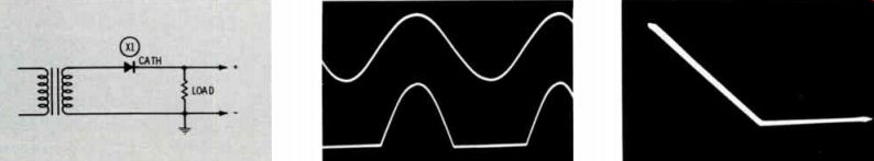
Fig. 3 Simple, unfiltered, half-wave rectifier circuit (A) Schematic of the
half-wave circuit.
Input voltage is 150 volts rms, DC output is +67 volts, AC output is 205 volts p-p and the load is 4.7K ohms. (B) Double-trace scope waveform of the input sine wave and the output rectified pulse; both are 60 Hz. (C) Scope waveform with the output pulse applied to the vertical amplifier of the scope and a 60-Hz sine wave used for horizontal deflection.
Rectifier circuits without capacitors are not typical in the power supplies of consumer electronic equipment. A half-wave rectifier with an input filter capacitor of 20 mfd is shown in Fig. 5A. The output waveform (hum or ripple) is a 60-Hz sawtooth, as shown in Fig. 5B. It is important for us to know, and remember, that the output is actually 95 percent pure DC with about 5 percent of sawtooth riding on top. The frequency of the saw tooth can be determined with a scope by the method given previously; the correct waveform is shown in Fig. 5C. Compared to the basic circuit voltages in Fig. 3, the voltages of Fig. 5 show a substantial increase in DC voltage, and an equally substantial decrease in p-p AC (hum), These differences are produced by the capacitor.
An Input Capacitor Causes "Peak-Reading" DC Voltages
Fig. 6 shows the relationships of p-p, peak and rms voltages. Since rectification uses no more than one peak for one diode, the peak voltage is the one of interest to us.
Peak voltage equals the rms voltage multiplied by 1.414.
In the rectifier circuits of Figs. 3A and 4A, each diode conducts current and voltage for a complete half cycle, because this is the time the anode is positive relative to the cathode. Adding a capacitor in parallel with the load resistance (Fig. 5A) causes the diode to supply power to the load, and charge the capacitor, during the time of conduction. In between diode conduction pulses, the capacitor partially discharges, to furnish power to the load. This partial discharge results in a sawtooth ripple, or hum, across the capacitor, as shown in Fig. 7B. Diode conduction cannot occur until the anode becomes more positive than the cathode. With the cathode connected to the positive end of the storage capacitor, only the tip of the input sine wave is more positive than the cathode/ capacitor voltage; therefore, diode conduction occurs for a short period of time, as shown in the waveform of Fig. 7A. The dotted lines in Fig. 7B were added to show the part of the sine wave during which the di ode current flows, while Fig. 7C shows the relationship between the rising edge of the sawtooth and the diode current (the scope width was expanded for better visibility). The voltage at the top of the sawtooth is the peak voltage (rms times 1.414) of the applied AC sine wave, less any losses. The amplitude of the sawtooth depends principally on the capacitance and the load. If the load is very light and the capacitance large, the output DC voltage will measure almost exactly the peak of the input AC voltage. This is the meaning of the old phrase "peak-reading". A 20-mfd capacitor added to the full-wave circuit, as shown in Fig. 8A, produces more DC and less AC (hum) at the output, and the hum is 120 Hz (see Fig. 8B). Frequency of the hum is verified on single trace scopes by using 60-Hz, sine wave horizontal sweep and applying the sawtooth to the vertical in put. A "bow tie" waveform, as shown in Fig. 8C, indicates the frequency is 120 Hz.
If negative voltage is desired from any of these four types of rectifier circuits, merely reverse the di ode(s) and the polarity of the filter capacitor.
Many variations of these basic circuits are possible. For example, Fig. 9A shows a rectifier circuit which supplies a positive output voltage, yet one side of the rectifier is grounded. This circuit was used to produce the waveforms of the capacitor current and diode current (Fig. 9B) by adding small resistors in series between anode and ground, and the negative plate of the capacitor and ground. The common ground necessary for operation of a dual-trace scope inverted the polarity of the pulse of that diode current.
Any rectifier circuit is a closed loop, and the basic operation is not changed by repositioning the ground connection. The ground is there only for the external circuits that constitute the load. Take the schematic of Fig. 9C as an example. It is the same as that of Fig. 5A, except for the grounding point.
Some power supplies have negative output, others have positive output, and some equipment (particularly solid-state types) might have both positive and negative voltage outputs. One model of solid state TV receiver stacks one power supply on top of another. To determine what the polarity of a power supply should be, follow this helpful rule:
-----------------------
(A) Schematic of the full-wave rectifier circuit. Input voltage is 150 volts rms on each side of the center-tap, load resistance is 4.7K ohms, DC output is +135 volts and the AC output (hum) is 210 volts p-p. (B) Scope waveform of the 60-Hz input sine wave and the 120-Hz full-wave pulse.
(C) The 120-Hz output pulse applied to the vertical amplifier of the scope and a 60-Hz sine wave applied to the horizontal amplifier.
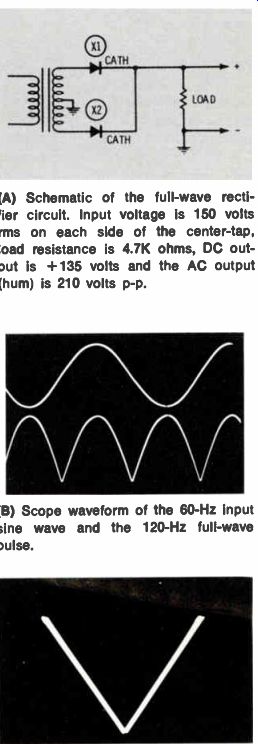
Fig. 4 A full-wave unfiltered rectifier circuit, using a center-tapped transformer.
-------------------
When rectified DC is obtained from a diode, the polarity of the voltage will be negative if it is taken from the anode, and positive if it is taken from the cathode. In Figs. 3A, 4A, 5A and 8A, the output voltage is obviously obtained from the cathode of the diode, and consequently is positive. The output voltage of Fig. 9A is from the cathode, through the transformer winding, and is also positive.
A rectifier circuit with both positive and negative voltages is diagrammed in Fig. 10A; the associated waveforms are shown in Fig. 10B. To change this circuit to one that produces twice the normal ...
---------------------
(A) Schematic of the half-wave rectifier with capacitor circuit. Input AC voltage is 150 volts rms, C1 is 20 mfd, load is 4.7K ohms, DC output is + 175 volts and AC output is 17 volts p-p.
(B) Input sine wave and the output saw tooth AC; both are 60 Hz.
(C) Scope waveform with the output sawtooth applied to the vertical amplifier and a 60-Hz sine wave applied to the horizontal amplifier.
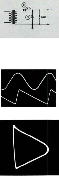
Fig. 5 An input electrolytic capacitor is added to the half-wave circuit to
make it "peak reading".
---------------
... amount of positive voltage (voltage doubler), it is necessary only to switch the ground to the -output terminal, as shown in Fig. 10C. The same circuit is redrawn in a more familiar configuration in Fig. 10D. It is very odd to see a diode connected from one side of the trans former winding to ground and a filter capacitor connected from the other side of the winding to ground, but Fig. 10C shows that the double voltage is obtained by connecting the negative and positive supplies in series. This is verified when the full-wave, 120-Hz output waveform in Fig. 10E is compared to the two 60-Hz, half-wave, alternate-conduction waveforms in Fig. 10B.
Shunt Rectifiers
All of the rectifier circuits de scribed previously were "series" types; which, incidentally, function just as well if the transformer shown is actually the one on the power company pole.
The other basic rectifier circuit is the shunt, or parallel, type. Al though it requires a resistive path somewhere across the input terminals, the rectifier diode and load are separated from the source voltage by the input filter (storage) capacitance. The other distinctive characteristic is that the entire input AC voltage also appears across the output, as shown in Fig. 11A.
Fig. 11B illustrates an unsuccessful attempt to filter out the huge amount of hum from the output.
Even when fed through a strong filter system consisting of a 680-ohm resistor and a 40-mfd capacitor with no DC load on the output, the hum measured 45 volts p-p. Because of the inherent hum, this circuit is useless for powering radios or TV receivers.
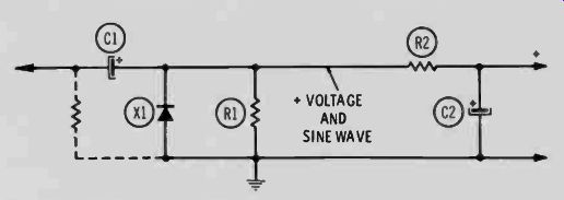
One very successful adaptation is to combine the shunt with a following series rectifier, as shown in Fig. 12. DC and nearly full line voltage are the output of the shunt rectifier. The series rectifier rectifies the AC sine-wave output of the shunt rectifier and adds the DC on top of the DC from the shunt stage to produce voltage doubling.
The output hum of this circuit is 60 Hz. Notice the polarity of diodes X1 and X2 in Fig. 12. X1 conducts on the negative side of the sine wave, and X2 conducts on the positive peak. In many doubler circuits such operation would double the frequency, but not in this case.
Because the large sine-wave output from the shunt rectifier circuit completely swamps any small amount of ripple that might be present, the hum output of X2 is 60 Hz.
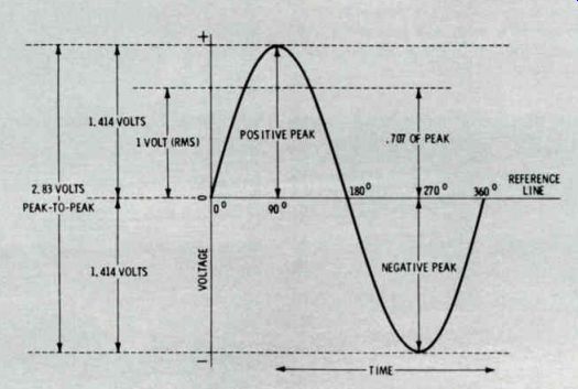
Fig. 6 Peak and rms voltages are enough to evaluate sine-wave AC voltages;
p-p voltages are necessary to measure correctly square waves or non-symmetrical
wave forms.
The voltage charts in Table 1 provide the values of the DC and hum voltages obtained from the circuit of Fig. 12 when the size of the two input capacitors and the value of the load resistor were changed.
I have known for many years that the capacitance of C1 and C2 would radically change the output DC voltage and hum. Even so, two items in the table surprised me: One was the reduced output hum voltage as the capacitance of C1 was de creased. The explanation is simple: Hum voltage is dependent on the series rectifier circuit-and it is supplied with less input DC and AC when the capacitance is decreased.
-------------------
(A) Top waveform is the 60-Hz input sine wave and the bottom waveform is the diode current (slightly broadened by the resistances in the circuit).
(B) The relationship of the input sine wave to the output sawtooth hum. The dotted lines were added to show the part of the sine wave during which diode current flows.
(C) Horizontal sweep width of the scope is increased to make the relationship between the sawtooth hum (at top) and the diode current more clear.
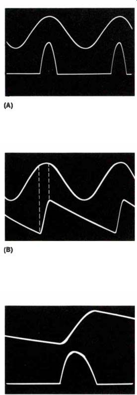
Fig. 7 Dual-trace scope waveforms of current and voltages in the schematic
of Fig. 5A.
-------------
(A) Schematic of the full-wave circuit using two diodes, a center-tapped trans former secondary and a peak-reading input capacitor. AC input voltage is 150 volts rms each side of center-tap, C1 is 20 mfd, load is 4.7K ohms, the output DC voltage is +195 and the output AC hum is 8 volts p-p.
(B) Waveforms of the 60-Hz input sine wave and the 120-Hz output sawtooth hum.
(C) "Bowtie" waveform obtained with the sawtooth hum applied to the vertical in put of the scope and a 60-Hz sine-wave horizontal sweep.
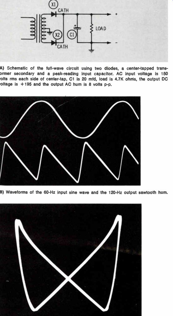
Fig. 8 A frequently used full-wave rectifier with capacitor input filter.
---------------------
The other surprise was the result when the capacitance of C2 was changed. When C3 is 0 mid, and C2 is changed to 0 mfd, the resultant output is +165 DC and 325 volts p-p 60-Hz sine wave, exactly the same as the output of the shunt rectifier. The only explanation is that the anode of X2 is positive relative to its cathode at all times; the peak DC and AC from the X1 circuit are the same.
Other applications of the shunt/ series type of voltage doubler are shown in Fig. 13. The load and quadrupler circuit is used during alignment of single- or over-coupled pairs of IF transformers in TV receivers, and it consists of two shunt/series doublers with the DC output voltages connected in series for increased output.
Fig. 13B shows the p-p rectifier circuit of the RCA WV98C VTVM. Other VTVM's and FET meters use solid-state diodes instead of the 6AL5, but the principle is the same. A p-p rectifier circuit must rectify both the positive and negative peaks, regardless of wave shape, and add the two voltages together for the complete reading.
Someone might question the practicality of this circuit, because it was previously stated that the output hum is the same frequency as the input voltage. However, it also was explained that one of the di odes conducted on the positive peak and the other diode conducted on the negative peak. Thus, the requirements for p-p measurements are fulfilled.
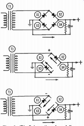
Fig. 8 (D) Schematic of a full-wave bridge rectifier circuit with peak-reading
input capacitor. Circuit action is similar to the fullwave circuit in Fig.
8A, except that the diodes switch at both ends of the transformer winding,
and the single non-tapped winding supplies power for both positive and negative
peak rectification.
(A) Schematic of a rectifier circuit with the rectifier grounded. The output voltage is positive in polarity.
(B) Capacitor current and diode current can be seen on the scope screen by adding small resistors (27 ohms or smaller) between capacitor and ground, and between diode and ground. Attach the scope leads across the resistors one at a time (both, if the scope is dual-trace type.) The slope in the base line of the capacitor current waveform is the discharge of the capacitor into the load. Heavier discharge between cycles increases this slope and might indicate a capacitance that is too small for the value of the load.
(C) Schematic of a rectifier circuit with the rectifier-transformer point grounded.
Operation is the same as that of Fig. 6A, except the load cannot be grounded.
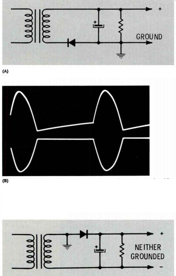
Fig. 9 Operation of a rectifier circuit is not affected by location of the
ground point.
(E) Scope waveform of the input sine wave and the output sawtooth of (C) and (D). The hum is 120 Hz; this circuit is both a voltage- and frequency-doubler.
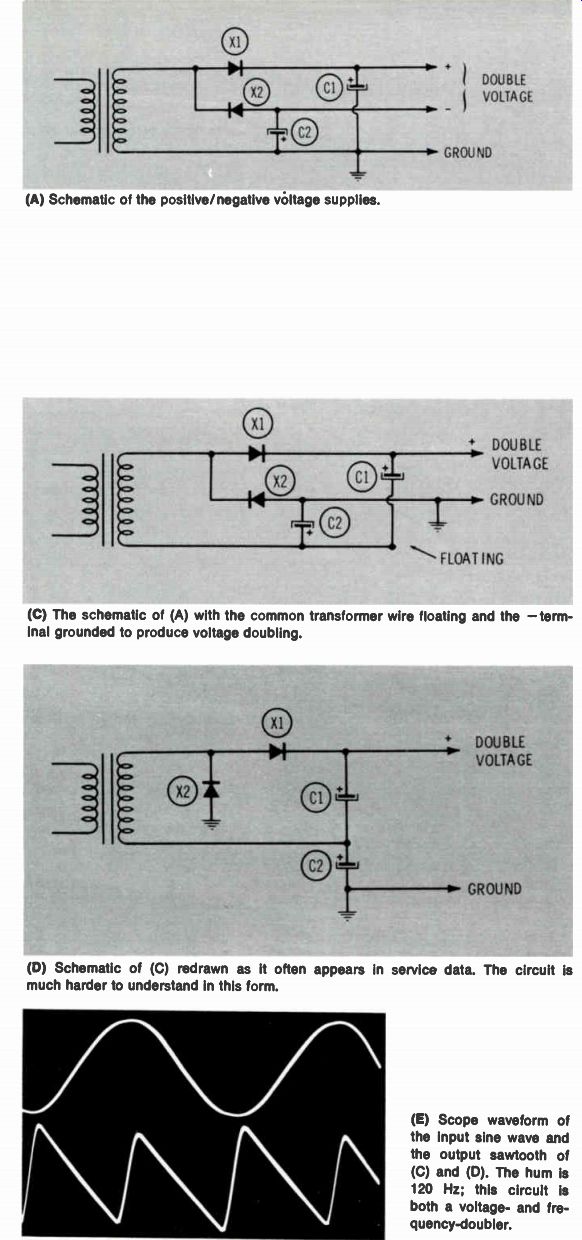
Fig. 10 Two halt-wave, peak-reading circuits can produce both positive and
negative voltages from one transformer winding.
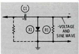
Fig. 11 (A) Schematic of a simple shunt rectifier with negative output.
(B) Schematic of a shunt rectifier with positive output and an extra RC filter
section. Input voltage is 120 volts rms, C1 is 20 mfd, R1 is 4.7K ohms, R2
Is 680 ohms (1 watt) and C2 is 40 mfd.
Output voltages obtained were: +160 DC and 330 volts p-p AC at the cathode of X1; +150 volts DC and 45 volts p-p AC at the output and C2.
NOTE: R2 becomes very hot; also, the hum is too large for most uses.
Fig. 11 Shunt rectifiers produce DC and full AC output.
----------
120 volts rms input, C2 is 20 mfd, load across C3 is 9.4K ohms
120 volts rms input, C1 is 20 mfd, C3 is 0, load is 9.4K ohms
Table 1 DC voltages and hum obtained with different sizes of capacitors and load resistors.
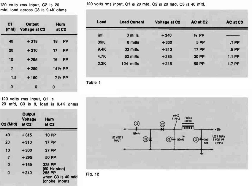
Fig. 12 Schematic of a typical voltage-doubler using both the shunt an series
rectifier circuits. The hum frequency is 60 Hz even though the rectifiers conduct
on opposite peaks.
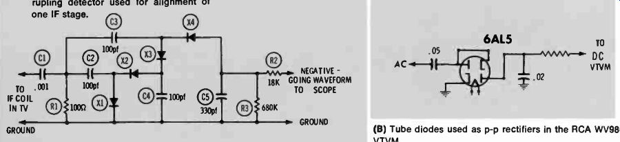
Fig. 13 Other uses for shunt and series rectifier circuits.
(A) Typical IF load and voltage quadrupling detector used for alignment of one IF stage. 0
(B) Tube diodes used as p-p rectifiers in the RCA VVV98C VTVM.
--------
Negative Voltage Made From Positive Peaks
To understand how it is possible to obtain negative voltage by rectifying positive peaks, consider the following facts:
• For diode conduction, the anode must be positive in relation ship to its cathode.
• When rectified DC is obtained from a diode, the polarity of the voltage will be negative if it is taken from the anode, and positive if it is taken from the cathode.
• Analyze the voltages and the electron current path, as shown in Fig. 15.
During the time the positive peak of the sine wave is present at the peak-reading capacitor, the capacitor charges through the low resistance of the diode, which is for ward biased by the capacitor current. When the positive peak is not maximum, the diode is no longer forward biased and is virtually an open circuit. The high positive end of the capacitor is grounded through the transformer winding (power wiring or circuit resistances in the case of VTVM's), and the capacitor partially discharges the stored power into the load. This end of the capacitor is highly negative relative to the plate that is connected to the transformer. The capacitor is replenished with power for the short period of time during each cycle when the anode of the diode becomes slightly positive, but the anode of the diode is negative for a much longer period of time (the rest of the cycle). Any DC meter will read this as a negative voltage.
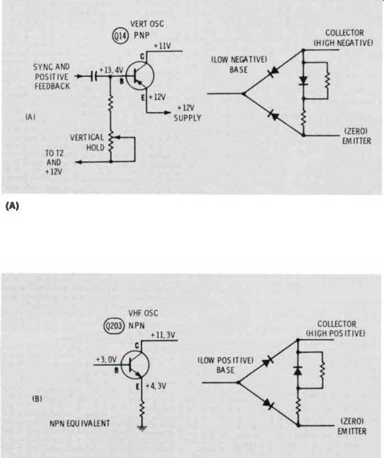
Base and Emitter of a Transistor Used as a Diode
The junctions of a transistor also exhibit diode characteristics. Fig. 16 shows two examples of rectification by the base/emitter junction.
The base of the transistor in Fig. 16A rectifies the pulse from the vertical output stage. A PNP-polarity …
--------------
(A) Schematic of the shunt rectifier.
(B) Electron flow during the small part of the cycle when diode current is charging the capacitor.
(C) Electron flow during the long part of the cycle when the capacitor is partially discharging into the load.
(D) The anode of the diode must be come positive relative to the cathode for conduction to occur. Only the positive peak of the input sine wave fulfills this requirement. The horizontal line shows the part of the sine wave during which diode current flows. Consider the line zero, and below it as negative.
(E) Dual-trace waveforms of the input sine wave and the diode current.
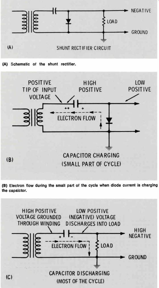
Fig. 15 Explanation of how a positive peak creates negative voltage in the
shunt rectifier circuit.
-------------------
… the transistor is operating as an oscillator or a class "C" amplifier.
The reverse bias must become for ward bias for a short period during each cycle.
Troubleshooting Power Supplies
The primary factors which affect the output voltage and residual hum of any power supply are:
• Input voltage and waveform (al ways should be checked).
• Diode condition, including for ward voltage drop and reverse current leakage. (Be sure an open in the wiring or a circuit board has not changed a full-wave circuit to a half wave.)
• Capacitor characteristics, including leakage and power factor.
• Load current (should be nearly normal). Many variations in symptoms and the extent of the defect are inevitable, but the cause of any power supply problem will be found in this simple list of four basic factors.
One open diode in the circuit shown in Fig. 8A or Fig. 8D will not stop all operation, but the DC voltage will be low and the hum level high, because a full-wave circuit has been changed to a half wave configuration by the defect.
A scope, VTVM or FET meter, and perhaps an accurate line-voltage meter, should be your primary test equipment for power supply problems. Fig. 17 shows some of the …
----------------------
(A) Shunt rectification of the vertical pulse by the base and emitter produces reversed bias. The transistor equivalent, with the junctions shown as diodes, shows why this is true. Shunt rectification creates a positive voltage because the base is the same as the cathode in a diode.
(B) The VHF oscillator transistor shunt-rectifies its own feedback signal and, because the base is the equivalent of the anode of a diode, the resulting voltage is negative, which measures as reverse bias.
Fig. 16 The base and emitter of transistors also can function as diodes. Both
examples are from the RCA KCS157 chassis.
(A) A leaking diode rectifier in the full wave circuit of Fig. 8A causes alternate capacitor charge/discharge waveforms to have an excessive amount of tilt between pulses.
(B) A leaking diode rectifier in the full-wave circuit of Fig. 8A causes al ternate hum waveforms to differ greatly in amplitude.
(C) An open C2 in Fig. 12 changes the circuit from peak-reading to choke-input and produces the lower waveform at the cathode of X2 when the load is light. With a heavy load, the waveform is damped to become a 120-Hz parabola, as shown in Fig. 4B. Fig. 16 The base and emitter of transistors also can function as diodes. Both examples are from the RCA KCS157 chassis.
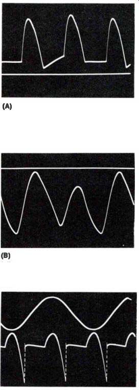
Fig. 17 Scope waveforms aid in diagnosing trouble in the power supply.
-------------------------
… visual signs of defective parts. Fig. 17A is the capacitor current in the circuit of Fig. 8A when the load is light but one of the diodes has excessive leakage. When the capacitor is part of a multiple unit can, it is difficult to look at the capacitor current, but Fig. 17B shows the difference in size of the alternate hum waveforms when a diode is leaking.
Fig. 17C shows the peculiar wave form produced on the cathode of X2 in Fig. 12 when C2 is open.
The sharp spike is an inductive kickback from the choke and C3.
At higher current, the waveform be comes more like that of Fig. 4B. In TV receivers, a pulse from the vertical output stage might be seen in some parts of the filter system.
Often this is normal. The source can be identified by making the vertical roll; if the extra 60-Hz pulse rushes across the screen of the scope, it is from the vertical sweep.
Or, disable the vertical and the pulse should be gone.
Practice measuring the hum frequency on several normal receivers until you can do it rapidly and accurately. This one technique might save you many hours of trouble shooting time.