The amount of solid-state units that have to be serviced is increasing, and, as a result, more and more service shops are turning to the in circuit transistor tester to reduce the time required to service these units.
At present, there are more than 30,000 electronic service shops using the in-circuit AC beta transistor tester. Many more would use this time saver if they knew more about its operation and applications.
The following paragraphs explain how the in-circuit transistor tester operates and how it is applied to re duce servicing time.
Operation With the tester connected to the transistor, the BETA CAL control is adjusted to the BETA CAL line on the meter. This sets the collector current to a normal level of about 2 milliamps, as shown in Fig. 1.
When the TEST or GAIN button is depressed, the meter is transferred to the base circuit, as shown in Fig. 2, and the amount of base current it took to give the 2 milliamps of collector current is read on the meter.
Because beta is the ratio of input current to output current, the meter can be calibrated directly in beta.
This is an extremely simple explanation, but the operation is just as simple and easy to perform.
Parameters
Beta is a very important parameter in a transistor because it indicates whether or not the transistor has enough gain (the ability to amplify a signal). As can be seen, the less base current it takes to produce the "set-up" collector current, the higher the beta or amplification of the transistor. This is the reason for the reverse-reading beta scale on these testers.
There is one more parameter that is just as important: leakage, or ICBO. Leakage is the reverse current that flows between the base and collector of a transistor, and is measured with the emitter lead open, as shown in Fig. 3.
Leakage in a transistor is import ant because it can affect the total operation of the circuit. Since the leakage current is in opposition to the normal current flow between the emitter and collector, it will lower the beta of the transistor. In many cases it may not lower the beta below the general beta spread of the transistor and, therefore, may not be detected during the beta test. The leakage measurement must be made out of circuit because any resistors or coils in the circuit will provide a path for the DC current and produce a false reading.
To measure leakage, a voltage of the opposite polarity is applied between the base and collector leads, and the resultant base current is measured on the meter. Normal leakage of a germanium transistor will be about 2 to 10 microamps in low-power types and up to 3 milliamps in power-output types.
The leakage in silicon transistors is much lower and, in many cases, may not even be indicated on the meter of the tester.
Connecting the Leads
The leads from the tester must be connected correctly to the transistor to be tested. With the transistor out of circuit, this is simple because the leads are easy to get to. The only difficulty that may be encountered is identification of the base, emitter and collector leads. Fig. 4 shows some of the more common base diagrams of transistors. When there is some doubt about lead identification, consult a transistor manual, such as Howard W. Sams Transistor Specification Manual, or Sencore's FET and Transistor Reference Book. Look up the transistor by number and refer to the base diagram indicated.
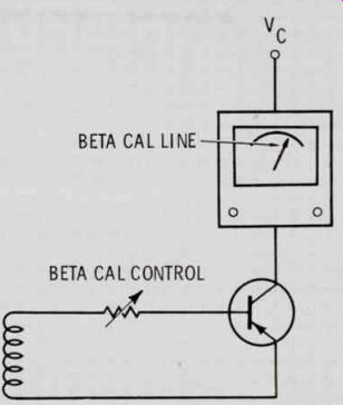
Fig. 1 BETA CAL control sets the collector current to a normal, or reference,
level of about 2 ma.
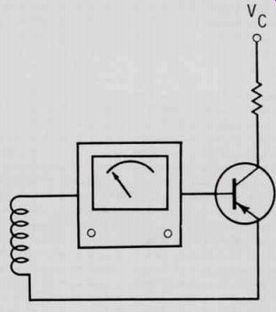
Fig. 2 Depressing TEST or GAIN button switches meter to base circuit. Meter
indicates amount of base current it took to produce 2 ma of collector current,
al though meter scale is actually calibrated in terms of beta.
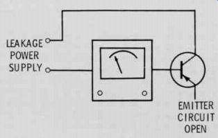
Fig. 3 Reverse current flowing between base and collector (ICB0) is measured
with this basic test setup.
Testing transistors in-circuit may be a little difficult. In many cases, transistors are soldered to the circuit board, and the leads are either too short or non-existent so that the test leads cannot be attached to them. To overcome this, connect the tester leads to the leads of a component that is connected to the different elements of the transistor, as shown in Fig. 5. A small light under the board will help trace out the leads and printed circuit for making the right connections.
After the transistor tester has been connected properly to the transistor, either in or out of circuit, rotate the BETA CAL control on the tester until the meter pointer rests on the BETA CAL line on the right hand side of the meter. As explained earlier, the collector current is now being set to a 2-milliamp reference level. With the meter calibrated, depress the BETA TEST or GAIN button, and read the beta direct from the meter scale. Most testers have two ranges of beta. In most cases, the high range will be used. The lower range will be used mostly for older transistors and many of the audio output transistors, since they have a lower beta figure than the low-power audio-driver transistor.
Checking for Defects
The chart on page 28 shows the meter indications for different transistor defects. For example, if one of the transistor elements is open, the tester will not calibrate out of circuit, but may appear to calibrate in-circuit due to current paths created by the circuit impedances.
When the gain or test button is de pressed, no beta reading will be obtained. For various other defects the tester will not calibrate or will not give a beta reading, indicating that the transistor or the circuit around it is defective. This will be the case in over 85 percent of the circuits that are tested. If the transistor tester can be calibrated and a gain reading in beta obtained on the meter, the transistor is not defective.
This simplicity and ease of testing is the one big reason why the in circuit AC beta transistor tester has become so popular for solid-state servicing.
Leakage
In some cases, a beta reading will be indicated, but the transistor will still be defective. There are several ways to tell if the transistor is at fault.
First, if the meter needle vibrates rapidly during the beta reading, it indicates that the transistor could be leaky or have excessive ICBO. The vibrating needle indicates that a large amount of current is being drawn from the power sup ply of the tester. Any time this is indicated, recheck the transistor for leakage out of circuit. (In low-impedance circuits, the circuit itself, or a defective component in the circuit, could also cause this effect.) If the transistor is not found to be defective, check the circuit for the source of the problem. In either case, the defect has been isolated to a given stage or component.
If the beta reading of the transistor being checked is low, it is generally due to leakage of the transistor.
It is a good idea to list on the schematic of the various sets that you service regularly, the beta readings taken in-circuit on a normally operating set. These readings can be used for comparison in the future. Also, consult a transistor manual for the values of beta that can be expected from the various types of transistors.
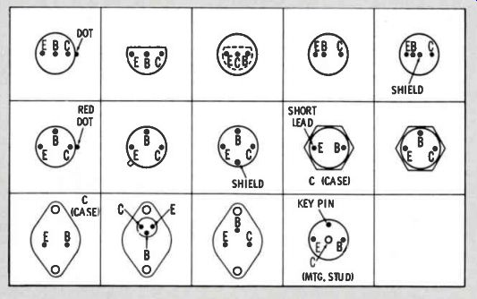
Fig. 4 Base diagrams of common transistor types currently in use.
BLACK LEAD E YELLOW LEAD B
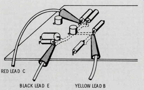
Fig. 5 Tester leads connected to components whose leads are electrically connected
to leads of transistor under test.
Examples of Application
Using an in-circuit transistor tester and the preceding information, servicing time on solid-state devices can be reduced. Here are a few examples and points that can be used for servicing solid-state devices in the shop.
The customer complained of distorted audio after his radio operated for several minutes. The unit was opened and the audio output transistor was replaced. When the unit was connected to the bench power supply, it operated normally for over 30 minutes without distorting, so it was buttoned up and returned to the customer. Two days later he returned the radio for servicing.
When asked how long it played before distorting, he said 30 minutes.
Without opening the unit, it was al lowed to play, and after 20 minutes, the sound became distorted. The output transistor was checked but it registered normal on both beta and leakage.
The audio stages were the most likely suspects, so beta readings of the transistors in the audio were taken and recorded while the unit was cold. The radio then was al lowed to play until the distortion became very noticeable, and another beta reading was taken. The reading of the first audio amplifier was almost half the value of the reading taken earlier, and the leakage was high when checked out of circuit.
When the transistor was tapped, the leakage changed, indicating an intermittent problem. The first audio amplifier transistor was replaced, and the radio returned to the customer, who reported much later that the radio played better than ever.
The moral: Don't jump to conclusions before having all the facts.
While servicing a small-screen, portable imported TV set, it was found that an exact replacement transistor is not always the answer.
The original complaint had been no video. Another technician had discovered that the first video amplifier transistor was defective, and had put in the recommended replacement transistor from a replacement line.
The result: a weak and washed-out picture. This prompted him to get an exact replacement transistor for the set, but it produced only slightly better results.
The in-circuit transistor test showed the driver and video output transistors to be high-gain types, while the exact replacement transistor was a low-beta type.
Another transistor in the set had the same markings as the replacement transistor so its beta was measured. It measured high.
The beta of various transistors in the general replacement transistor stock was checked. One transistor out of the group was high, but just under that of the driver and output stage. This was installed and the picture improved. The FET and transistor reference book was consulted, and it was discovered that the general replacement transistor was usable since its beta reading of 75 fell within the indicated normal beta spread of 50 to 180. However, the transistor that finally solved the problem had a beta of 165. Apparently, the design of the video circuit left much to be desired and would work only with high-beta transistors in all three stages.
In most cases, the circuit will operate normally with a transistor whose beta falls within the given beta spread of the general replacement transistor, but don't overlook the fact that some circuit designs are more gain sensitive than others.
Other Tips About Transistors
There is such a thing as an intermittent transistor. The AC beta can be checked hot or cold. Using freeze spray can speed up servicing time.
Connect the in-circuit tester to the suspected transistor, and check the beta. While depressing the TEST or GAIN button, spray the transistor with the freeze spray. If the beta reading disappears, the transistor is defective. Beta gradually de creasing is normal for a transistor operating in cold ambient temperatures. Any sudden or drastic change indicates a thermally intermittent transistor.
Another problem involves the transistor that is not listed in any specifications book. In this case, look for a transistor with markings similar to the defective transistor, and use its beta reading to select a replacement transistor. Usually a similar transistor can be found in the TV set, but if not, look for one with a similar function, such as an audio driver for a video, horizontal or vertical driver.
In the IF there are usually three transistors. Compare the two good ones and average the readings. IF and RF transistors generally have lower beta than audio transistors.
Conclusion
Servicing time can be reduced by using the in-circuit transistor tester.
The amount of time saved is de pendent on the technician's knowledge of the operation and application of the instrument and his ability to interpret the information it sup plies. A thorough understanding of the parameters and peculiarities of solid-state devices is also essential to quicker solid-state servicing.
----------
Transistor Tester Meter Indications For Defective Transistors
TROUBLE METER INDICATION
Open Base, Emitter or Collector Base to Emitter short Base to Collector short Emitter to Collector short Collector and Base leads inter changed Emitter and Collector leads interchanged Base and Emitter leads interchanged Cannot BETA CAL when transistor is tested out of circuit. In circuit tester may BETA CAL through circuit impedances but no beta reading can be obtained when GAIN button is de-pressed.
Tester will BETA CAL but TYPE switch must be in wrong position. Beta reading will be all the way to left or greater than infinity with meter pointer vibrating.
Tester will BETA CAL, but when GAIN button is depressed, meter indication will not change.
If there is a dead short, tester will not BETA CAL. If there is a low resistance short the tester may BETA CAL, but the meter needle will vibrate rapidly when checking beta.
Tester will BETA CAL, but meter reads to right (a beta of less than one). Tester will BETA CAL, but meter may read to right (a beta of less than one). Indicates a very low beta figure. A few transistors may read the same because they are made to have the Emitter and Collector leads transposed.
Transistor will BETA CAL as opposite-polarity transistor, and no Beta reading is obtained when GAIN button is depressed.
------------------------