2-1
The television system in use today is essentially an electronic system. It was made possible by the development of the cathode ray tube which is the heart of both the television transmitter and receiver.
As was pointed out in Section 1, all television systems must satisfy the 'requirements of the human eye. The cathode ray tube does this remarkably well and television as we know it today has been designed around this tube.
The cathode ray tube performs the two most important functions of the television system. At the transmitter, it "sees" the scene to be televised and transforms it into an electrical signal which can be passed on to the television receiver where the second important function takes place. Here again a cathode ray tube is used to take the electrical signal and from it reconstruct the original scene in the form of a visual picture on the viewing screen.
A brief resume of the history and origin of the cathode ray tube is a good starting point for the discussion of the tube's construction and operation which follow.
The term "cathode ray" was originated in the last century by a scientist, Jules Plucker, who was investigating the properties of gases. His experiments included putting the gases being studied into cylinder-like glass envelopes. In these glass envelopes, there were two metal plates which were connected to a battery. (Figure 1.) The plate connected to the negative end of the battery was called a cathode, while the plate connected to the positive end was given the name anode. In the experimental procedure, a pressure reducing pump was attached to the tube through an opening. It was discovered that as the pressure was reduced, the region of the cathode acquired a definite, greenish glow. Plucker attributed this glow to invisible rays which, he believed, came from the cathode. He therefore called them "cathode rays".
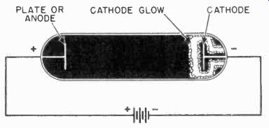
Figure 1. Plucker's simple gas tube.
Although its basic shape and components were changed, the same type of tube was used in later experiments in the study of gases. Still later, the tube found use as an indicating unit using the cathode rays as a pointer. It was found that as an indicator, it functioned best with almost all of the gas pumped out.
Nevertheless, the name "cathode ray tube" has remained in use, even though at the greatly reduced pressure now utilized, the green colored region in the neighborhood of the cathode is no longer evident, and the alleged "cathode rays" proved to be merely electrons.
2-2 Modern Cathode Ray Tubes. The modern cathode ray tubes now used in television differ considerably in construction and appearance from Plucker's original gas tube. A Type used in present day receivers is shown in Figure 2. Cathode ray tubes designed for television receivers have been given various names by tube manufacturers. Some of these are "kinescope", "teletron", and "visitron". Since there has been no universal acceptance as yet of a name for the receiver tube, the term "picture tube" will be used in this text whenever reference is made to the receiver cathode ray tube.
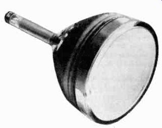
Figure 2. A modern cathode-ray tube used in television receivers. (courtesy
GE)
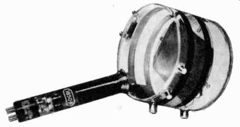
Figure 3. The Iconoscope, a cathode-ray tube used in the television camera.
(courtesy RCA)
There are several types of cathode ray tubes used in the television camera. One of the earliest designs, illustrated in Figure 3, is known as the "iconoscope". This word stems from the Greek word icos, which means "I see". The name is descriptive of the tube, since it actually does see the scene being televised and can change what it sees into electrical signals.
PICTURE TUBE CONSTRUCTION
2-3 Since the heart of the television camera and receiver is a cathode ray tube, it is best to begin the discussion of the modern electronic television system with a description of this tube.
Of the two basic types, the picture tube and the camera tube, the former is more fundamental and a little easier to understand. It is therefore treated first.
Figure 4 shows a cross-sectional drawing of a picture tube, including its component parts and an imaginary electron beam, number 8, to illustrate the action of the various elements of the tube upon the beam.
The modern picture tube consists of five main sections: (a) a glass envelope, (b) a base which is outside the envelope, (c) the electron gun assembly, (d) the deflection plate assembly, and (e) the screen. The cathode, number 5, provides a source of electrons which are attracted in the general direction of the screen, number 19, by the action of the electron gun. These electrons are molded into a very narrow beam, which can be focused to a small point at the screen.
The inside of the screen is coated with a material which lights up when bombarded by the stream of electrons. The property of the screen which causes it to emit light when struck by the electrons is called fluorescence. When properly focused, the electron beam will strike the screen, causing a very small area of the screen to glow. If the face of the tube is viewed, this area will be a small pinpoint of light.
The deflecting plates, numbers 14, 15, 16, 17, can be made to move the beam up, down or sideways (vertically or horizontally). It is possible to apply electrical signals to these plates and cause the beam to move so fast that the eye cannot detect its movement. Since the screen material glows for a short time, even after the electron beam has moved to another position, a pattern can be traced on the screen similar to the one shown in Figure 5. Though the beam is constantly moving while tracing out this rectangular pattern, the pattern actually appears stationary because of the after-glow of the screen and the persistence of the eye.
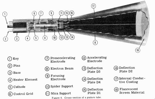
--------------Fig. 4. Cross section of CRT.
2-4 The Electron Gun. The electron gun is so named because it takes the electrons given off by the cathode and accelerates them somewhat in the manner of a gun. The electron gun can be subdivided into four parts: (1) the cathode-grid assembly; (2) the pre-accelerator assembly; (3) the focusing electrode assembly; and (4) the accelerating electrode assembly. The assemblies are all supported by ceramic or glass rods which run the entire length of the electron gun as shown in Figure 4, number 10.
These rods are usually made of a non-conducting ceramic or glass material to prevent electrical inter-action between the various parts of the gun.
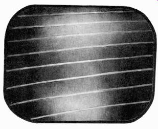
Figure 5. Illuminated pattern obtained on the screen of a picture tube when
the electron beam is rapidly moved vertically and horizontally.
2-5 The Cathode-Grid Assembly. The cathode-grid assembly consists of the heater element, the cathode, the control grid, and other supporting components, as shown in Figure 6. This illustration is an exploded view of the cathode-grid assembly and does not show the actual spacing of the components. The heater element, a coiled wire, is usually made of tungsten or an alloy of tungsten. This material is chosen because it is easily heated to a high temperature when an electrical current passes through it.
The cathode is a thin metal sleeve surrounding the heater coil.
The metal sleeve, usually nickel alloy, is coated on one end with a substance which emits electrons in great quantities when heated sufficiently. This substance is usually an oxide, such as cesium oxide. The cathode is electrically insulated from the heater and is therefore said to be indirectly heated. Indirect heating is used because it isolates the emission qualities of the cathode from the power source supplying the current to the heater, and permits the use of an alternating current source.
If alternating current were applied directly to the cathode to heat it, the flow of electrons would fluctuate according to the frequency of the current. Early cathode ray tubes used a heater-cathode assembly in which the heater itself emitted the electrons. For proper operation, these tubes required a direct current heater supply. Because it is more economical to supply the current for the heater from an a-c source, the indirectly heated cathode is now used almost exclusively.
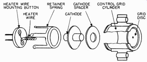
Figure 6. The cathode-grid assembly.
The control grid in the cathode-grid assembly is a cylinder, completely surrounding both the heater and the cathode. The grid is open at one end, but closed at the other end by a disc.
The disc has a small hole in its center to permit the passage of electrons. Since all electrons which pass to the screen must go through the hole in the disc, the grid electrode can assist in controlling the electron flow.
2-6 The Pre-Accelerator Electrode Assembly. The pre-accelerator electrode assembly is shown in Figure 7. It usually consists of two parts, A and B, each of cylindrical shape, with several discs enclosed in them. All of the discs have holes in their centers to permit the passage of the electron stream.
This assembly gets its name from the electrical function it performs in the electron gun. It causes the electrons to move more rapidly in the direction of the screen. Its function is essentially the same as that of the accelerator (to be mentioned later), which also increases the speed of the electrons. Since the electrons pass through this electrode before they pass through the accelerator, it has been named the pre-accelerator.
DISC; CYLINDER A; CYLINDER B
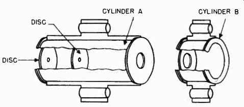
Figure 7. The pre-accelerator electrode assembly.
2-7 The Focusing Electrode Assembly. The focusing electrode assembly performs the function which its name implies. It focuses the electron beam to a fine point on the screen. (Figure 8) The focusing electrode assembly. The focusing cylinder is shorter in length than the grid and pre-accelerator electrodes, but is of essentially the same shape.
It does not contain the discs included in the grid and pre-accelerator electrode assemblies.
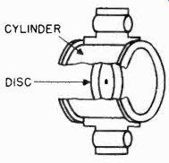
Figure 9. The accelerating electrode assembly.
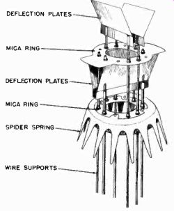
Figure 10. The deflection plate assembly.
2-8 The Accelerating Electrode Assembly. The accelerating electrode assembly performs the same function as does the pre-accelerator. It increases the speed of the electrons traveling toward the screen. The construction of the accelerating electrode is shown in Figure 9.
2-9 The Deflection Plate Assembly. The deflection plate assembly, shown in Figure 10, is mounted between the electron gun and the fluorescent screen. This assembly consists of two pairs of rectangular metal electrodes referred to as deflection plates. The four deflection plates are mounted with the aid of two mica rings which support and insulate them from one another and from the electron gun. A spider spring, made of a flexible metal material, centers the deflection plate assembly in the neck of the picture tube. As the electrons travel from the electron gun to the fluorescent screen, they must pass between each of the pairs of plates. The deflection plates are so placed in the tube that if a voltage differential appears across either pair, it will cause the electron beam to be deflected. Since the pairs of plates are mounted at right angles to one another, either horizontal or vertical deflection is possible by applying an electrical signal on the proper pair.
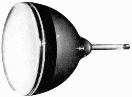
Figure 11. The glass envelope is coated on the inside with a conducting material.
The second anode cap is connected to the aquadag coating. (courtesy DuMont)
2-10
The Envelope. All of the elements of the picture tube are mounted inside of a glass envelope. Almost all air is evacuated from this envelope which must be strong enough to withstand the pressure of the atmosphere.
The inside of the glass envelope between the neck and the screen is coated with a conducting material, as shown in Figure 11A. Graphite is the major component of this material which is known commercially as “Aquadag" or "Dixonac". The coating is connected to the accelerating electrode so that it operates at the accelerating potential. In picture tubes which operate at very high accelerating potentials, a small metal contact is fused to the funnel portion of the tube. The second anode and aquadag coating are connected to this contact instead of to a pin in the base. Figure 11B shows a picture tube with this type of construction. When stray electrons approach the coated insides of the tube, the high potential on the coating repels them backward toward the accelerating anode, so that electrons striking the walls of the tube are returned to the circuit. The potential on the conductive coating also eliminates inter-action between the electron beam and electrons rebounding from the screen.
Some picture tubes are equipped with an additional element referred to as an intensifier band. The intensifier band consists of a ring of graphite, coating the inside of the tube envelope. A non-conductive coated area between the intensifier band and the accelerator coating insulates the two coatings from each other. A small metal pin is inserted through the glass at a point where it will contact the intensifier band so that an electrical connection can be made to the band. Since the intensifier ring completely encircles the electron beam, it does not affect the path of the beam once the beam has been deflected. The purpose of the intensifier band is to further accelerate the electrons without making it more difficult to deflect the beam. If the beam is traveling too fast, deflection is quite difficult, requiring extremely large electrical signals on the deflection plates. With an intensifier band tube, it is possible to deflect the beam when it is moving at low speed when deflection is relatively simple. Then, after the beam has been deflected, the voltage on the intensifier band imparts to the beam additional acceleration to provide a brighter image on the screen.
2-11 The Tube Base. Except for the fact that it is larger and usually has more pins, the picture tube base is similar to an ordinary vacuum tube base. The leads which connect to the various parts of the internal assembly of the tube are brought through the glass seal at the end of the tube and are inserted into pins in the base.
2-12 The Fluorescent Screen. The fluorescent screen consists of a thin chemical coating which is deposited on the inside face of the tube. This coating consists of a silicate, sulphide, sulfate, or tungstate, and a binding material which holds the chemical to the glass. The thickness and uniformity of the coating are very critical and must be held within very narrow margins to assure uniform color and light output when the electron beam impinges upon the screen.
OPERATION
2-13
All of the parts of the picture tube just described perform important functions. The principle parts of the picture tube will now be discussed from an electrical standpoint, for the purpose of assisting the reader to understand their operation.
2-14 The Heater Coil. The sole function of the heater coil, or filament, is to heat the cathode to its proper operating temperature. No useful electron emission takes place from the heater coil. The manner in which the heater converts electricity into heat may be understood from a simple discussion of electricity.
INSULATING SLEEVE FILAMENT CATHODE CYLINDE OXIDE COATED EMITTING AREA
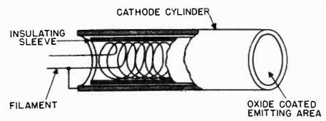
Figure 12. Heater and cathode assembly.
All material consists of small particles called atoms. Included in each atom are small negatively charged particles referred to as electrons. The wire which makes up the heater coil, therefore, consists of atoms and the electrons which are part of them.
When a potential is placed across the ends of the heater wire, it causes electrons to be released from their atoms. These electrons move along the wire and constitute a current flow. The moving electrons strike other atoms and electrons which oppose their motion. This opposition is referred to as "resistance". As a result of the opposition or resistance to the electron flow, some of the energy which causes the current to flow is converted into heat.
2-15 The Cathode. The cathode must supply the electrons which later are formed into the beam which is directed toward the face of the tube. It is placed over the heater coil so that the heat generated by the filament can be radiated to it (Figure 12). The cathode is insulated from the filament so that no electrical inter-action may take place. When heated to a temperature of about 700 degrees centigrade, the oxide coated cathode emits comparatively large amounts of electrons. To perform most efficiently, the cathode must emit the largest possible number of electrons at the lowest possible temperature. It has been found that certain oxides of alkaline earth metals such as cesium meet these requirements and are best suited for the cathode coating.
CONTROL GRID ELECTRON BEAM
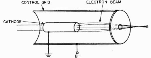
Figure 13. The grid limits the number of electrons which pass to screen.
2-16
The Grid. The electrons emitted from the cathode must pass through the hole in the grid. The grid controls the number of electrons which flow through the accelerator electrodes.
When a more negative potential than the cathode potential is placed on the grid. it decreases the number of electrons which pass through the hole in the grid. When the negative charge on the grid is varied, the number of electrons passing through the hole in the grid also varies. The grid can therefore be used to control the number of electrons in the beam, and for this reason, is usually referred to as the control grid. If the negative charge on the grid is great enough, the electron beam will be entirely cut off.
The control that the grid can exert over the electron beam is one of the important features of the picture tube which have made electronic television possible. The greater the number of electrons (beam current) in the beam, the greater will be the light output from the screen. When the television signal is fed to the grid, it controls the passage of the electron beam and thus the intensity of the glow of the screen.
2-17 Grid Action. In order to control the stream of electrons passing to the screen, the grid is placed around the cathode (Figure 13). The cathode and grid in a cathode ray tube function in the same manner as the cathode and grid in a conventional vacuum tube. If the grid were at the same electrical potential as the cathode, the electron beam would be limited only to those electrons which were traveling along an axis which passes through the small hole in the disc at the end of the grid.
The action of the disc on the electron beam, however, is not sufficient to limit the beam properly. It also does not provide a means for changing the number of electrons in the beam. Therefore, the grid is given a potential more negative than the cathode and this potential is made variable.
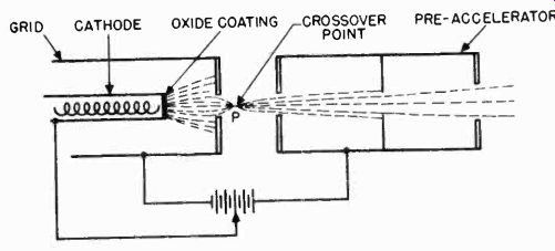
Figure 14. The "crossover" point of the electron beam is between
the grid and the pre-accelerator electrode.
Some of the electrons which are emitted by the cathode do not go through the grid opening. This is because the cathode is much more positive than the grid and exerts a greater attracting force on the electrons than do the positive potentials on the more remote accelerating anodes. At the same time the negatively charged grid repels the negative electrons back to the cathode. This action of the grid in repelling electrons is aided by the presence of what is called a «« space charge" which exists around the cathode. The space charge is created by the electrons themselves. Some of the electrons in breaking away from the cathode do not have sufficient energy to reach the grid.
These electrons hover around the cathode as a sort of electron cloud and sometimes even return to the cathode. The space charge created by these electrons forms a barrier for other electrons which are freed from the cathode. If the new electrons do not possess a sufficient amount of energy to penetrate the space charge, they are forced back to the cathode. With these factors: (1) the negative grid, (2) the space charge, (3) the attraction of the cathode for the electrons, and (4) the small opening in the grid disc, it is very difficult for electrons to pass through the grid to the accelerating assembly beyond. Many electrons, however, break free from the cathode with sufficient energy to overcome these barriers and pass through the opening in the grid.
CONVERGING LENS (GRID ACTION) LIGHT SOURCE (CATHODE) CROSSOVER POINT
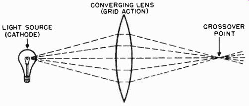
Figure 15. The focusing of an electron beam is similar to the action of a
lens on a beam of light.
The electrons which pass through the grid, because of the pulling forces exerted by the positive charges on the accelerating electrodes, converge into a narrow beam. This convergence is due to the relatively high negative potential at the grid which makes each forward traveling electron move toward the axis of the electron beam. The cumulative actions of the electrical fields at the grid and at the pre-accelerator electrode causes the paths of the electrons, which pass through the grid, to meet and cross over at point P as shown in Figure 14. This point is called the "crossover point" and is between the grid and the pre-accelerator electrode.
The field between the grid and the pre-accelerator electrode acts on the electron beam in a manner similar to the action of a lens on a beam of light. In fact, the substitution of an "electrostatic" lens for the grid and pre-accelerating electrode, as shown in Figure 15, may help the reader to understand the action of these electrical fields in narrowing down the electron beam to the crossover point.
2-18 The Pre-Accelerator. In early cathode ray tubes the focusing electrode was located right in front of the control grid.
With this type of construction, adjustments of the voltage on the focusing electrode effected the grid action and changed the intensity of the electron beam. In more modern tubes this interaction is prevented by the pre-accelerator electrode which is inserted between the control grid and focusing anode, as shown in Figure 16. The pre-accelerator is connected directly to the second anode and provides the initial acceleration of the electron beam.
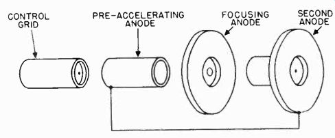
Figure 16. The pre-accelerator electrode is inserted between the control
grid and the focusing anode.
Focusing Electrode. After the electrons converge at the crossover point, they begin to spread out again. A means had to be provided to force the electrons back to the axis of the tube and retain the narrow beam until it reaches the screen. Two methods are used in modern picture tubes to focus the beam in this manner. They are called (1) electrostatic focusing and (2) electromagnetic focusing. The term focusing is used because of the similarity to the focusing of a light beam by an optical system.
Electrostatic focusing is most easily understood by referring to an optical analogy of the action of an electrical field on an electron beam. With a lens, light rays can be made to converge to a point and afterwards they will begin to diverge again. The diverging beam can then be made to converge once more, by introducing another lens as shown in Figure 17.
By substituting lenses of different curvatures for the second lens, the distance to the second crossover point can be varied.
If a screen is located a certain distance away, the light rays can be made to cross over, or focus, at the screen by the proper selection of lens curvature.
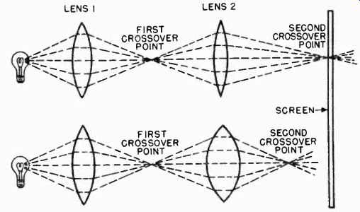
Figure 17. The distance to the second crossover point is determined by the
curvature of lens 2.
GRID PRE-ACCELERATOR(A) ELECTROSTATIC LENS CATHODE 1 FOCUSING ELECTRODE(B) ACCELERATING ANODE(C)
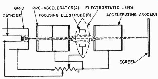
Figure 18. The electrostatic field inside the focusing electrode focuses
the electron beam to a second crossover point.
If an "electrostatic lens" and an electron beam are substituted for the optical system and light beam, electrostatic focusing can be illustrated as in Figure 18. As the beam of electrons leaves the pre-accelerator assembly, it is diverging. This divergence is caused by the fact that the focusing electrode, (b), is more negative than the pre-accelerator, (a). The repelling force set up by the more negative focusing electrode slows up the electrons and makes them scatter. As the diverging electrons pass from the focusing electrode, (b), into the field between the focusing electrode and the accelerator, (c), their speed is once more increased, since the accelerating anode is more positive than the focusing electrode. The electrostatic field again acts in the manner of a lens and focuses the electron beam to a second crossover point. This crossover is adjusted so that it occurs at the screen.
HORSESHOE MAGNET
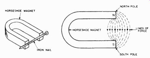
Figure 19. Left, the magnetic field between the poles of the horseshoe magnet
pulls the nail to the magnet. Right, the lines of force around a horseshoe
magnet.
The electrostatic focusing action must take place for many different beam currents. These differences in beam current are caused by the potential on the grid. To compensate for this, the potential on the focusing electrode is made variable so that the electrostatic fields on each side of it may be made weaker or stronger to permit the focusing of smaller or larger amounts of beam current.
2-20 Electro-Magnetic Focusing. Electro-magnetic focusing is another method that is used to focus the stream of electrons to a point on the screen. Whereas in electrostatic focusing the focusing action is accomplished by applying d-c voltages to the electron gun in the manner previously discussed, electromagnetic focusing is accomplished by placing a coil of wire over the neck of the picture tube, and passing a d-c current through the coil. Electromagnetic focusing action may be more easily understood by reviewing the basic theories of magnetism.
Between the ends or poles of a horseshoe magnet, such as shown in Figure 19A, there exists a field of magnetic force.
The existence of this field can be demonstrated by holding an ordinary iron nail near the poles of the magnet. As the nail is brought close to the poles, the magnetic field will pull the nail to the magnet. When the nail is some distance from the magnet (outside of its magnetic field), there is little pulling action. The extent of the magnetic field surrounding the magnet is determined by the degree to which the metal in the magnet is magnetized.
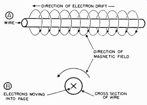
Figure 20. Direction of electron current flow in, and direction of magnetic
field surrounding, a wire.
In an attempt to picture a magnetic field, it is assumed that it consists of lines of force or flux. The lines of force around the horseshoe magnet are shown in Figure 19B. Notice that the flux extends in one direction from one pole to another. The pole at which the lines originate is called the north pole, and the pole at which they terminate is called the south pole.
A similar magnetic field surrounds electrons. An ordinary metal wire is made up of atoms which contain electrons. As explained above, each magnetic field has a definite direction; that is, the lines of force travel from one point to another. When no current flows through a wire, the electrons in it lie at random, and the directions of the magnetic fields around the electrons are so different from each other that they effectively cancel out. The net effect is that no magnetic field is set up outside of the wire. However, when a current flows through a wire as shown in Figure 20A, the electrons flow in one direction only.
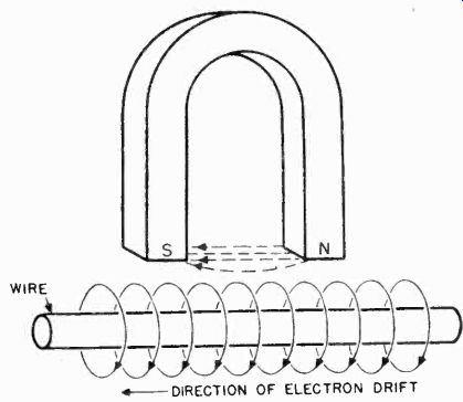
Figure 21. A wire which is parallel to the magnetic lines of force set up
by a horseshoe magnet is not influenced by the magnet.
Since the electrons all move in the same direction, their magnetic fields all act in the same direction. This direction is around the axis of the wire. The accumulative effect of the magnetic fields of the electrons acting in the same direction, is the creation of a magnetic field around the wire. Looking at the wire along its axis, as shown in Figure 20B, if the current were going into the page as indicated by the x, the magnetic flux would flow in a circle around the wire in a counter-clockwise direction.
If the current in the wire were flowing in the opposite direction, the magnetic flux would flow clockwise.
From the previous discussion, it has been shown that magnetic fields can be produced by two methods:
1. By magnetizing certain metals such as iron (a horseshoe magnet).
2. By sending a current in one direction through a wire.
When a number of fields of magnetic force are merged, they either add to create a more powerful field or cancel each other, resulting in a diminished field. The factor which determines whether they will add or cancel is their direction or polarity.
WIRE MOVES TO LEFT
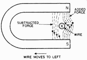
Figure 22. Wire placed at right angles to the lines of force from the horseshoe
magnet.
Suppose a wire with a d-c current flowing through it were placed near the poles of a horseshoe magnet, as shown in Figure 21. The wire is parallel to the magnet lines of force set up by the horseshoe magnet. Under these conditions, the magnetic field surrounding the wire is at right angles to the horseshoe's magnetic field. The two fields neither aid nor oppose each other, and therefore, they will not influence one another.
If the wire is now placed at right angles to the lines of flux from the horseshoe magnet, the fields will be in the same direction on one side of the wire, and in opposite directions on the other side. Looking at the end of the conductor, the fields appear as in Figure 22. To the right of the wire, the magnetic fields from the horseshoe magnet and from the current flowing in the wire are in the same direction. To the left of the wire, the directions of the two fields oppose each other. The result of this opposition to the left of the wire and reinforcement to the right of the wire is that of forcing the wire to the left.
If an electron beam is substituted for the wire with current flowing in it, a similar action will take place, and the beam will be forced into a different path, because a magnetic field surrounds the electron beam in exactly the same manner as it does a wire carrying a direct current (Figure 23). An electron beam flowing in the direction indicated and at right angles to a magnetic field will be forced to the left just as was the wire in Figure 22.

Figure 23. Direction of magnetic field set up by an electron beam.
SOLENOID DIRECTION OF MAGNETIC FIELD
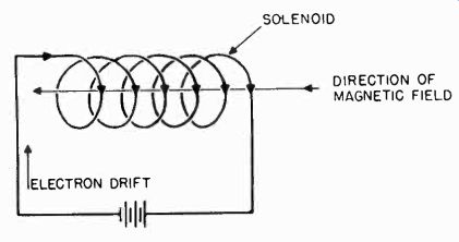
Figure 24. Direction of magnetic field in a solenoid.
The ability of a magnetic field to move an electron-beam from its path when the beam is traveling at right angles to the field is the principle upon which magnetic focusing is based.
In magnetic focusing, an electro-magnet is used instead of a permanent one. An electro-magnet consists of many turns of wire wound in the shape of a coil. Such a coil of wire is called a solenoid. If current flows through a solenoid, the addition of the magnetic fields created around each turn of wire results in lines of force which travel along the axis of the solenoid, as shown in Figure 24. If this solenoid is fitted around the neck of a cathode ray tube in which electrons are flowing, there will be two sets of magnetic fields in action: (1) the field due to the electron beam, and (2) the field due to the current flowing in the solenoid. As shown in Figure 25, electrons (A) traveling along the axis of the solenoid are not affected since the field due to the electrons is parallel to the magnetic field of the solenoid.
Electrons which are diverging from the axis of the tube are affected (B and C). The magnetic field due to the diverging electrons is reinforced on one side but opposed on the other side, and thus the electrons are forced back to the axis of the tube.
Since the electrons are moving forward, in addition to the side motion resulting from the field surrounding the solenoid, they follow a spiral path through the magnetic field created by the focusing coil. After leaving the magnetic field surrounding the solenoid, they continue to approach the axis of the tube. Electrons (A), (B), and (C), therefore, converge again.
By properly locating the solenoid (referred to as the focusing coil) and correctly adjusting the current through the coil, the paths of electrons passing through the coil can be changed so that all of the electrons meet at the screen to form a small, "focused" spot. If the current in the coil or the location of the coil is changed, the beam will no longer be focused on the screen.
FIELD IN SOLENOID
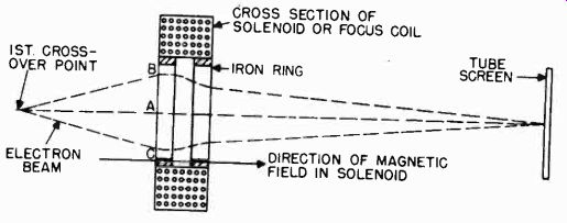
Figure 25. Focusing of an electron beam by a magnetic field inside of a solenoid.
2-21 Focus Coil Construction. Commercial focus coils (Figure 26) are made by winding many turns of wire around a soft iron core. An air gap is left in the center of the iron core (Figure 25) to concentrate the lines of flux at the center of the focus coil. By concentrating the flux in this manner, stray magnetic fields around the coil are reduced and are less likely to magnetize the elements of the electron gun. Concentration of the field increases the efficiency of the coil and reduces the direct current required to set up a sufficiently strong focusing field.
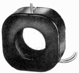
Figure 26. A commercial focus coil. (courtesy RCA)
In practice, the focus coil is moved along the length of the tube neck to obtain the best focusing of the beam on the screen.
Fine adjustments of the focusing action are made by changing the current flowing through the coil.
2-22 Electromagnetic Focusing vs. Electrostatic Focusing.
Since the use of electromagnetic focusing eliminates the need for a focusing electrode, the electron gun structures used in magnetic tubes are simpler and more economical than those used in electrostatic tubes. The focusing action secured with the electromagnetic focusing system is generally better than that obtained with electrostatic focusing. Electromagnetic focusing usually gives a smaller minimum spot size. This is a distinct advantage as the reader will realize later.
2-23 Deflecting the Electron Beam. Part of the job of creating a television picture on the screen of a picture tube consists of moving or "deflecting" the electron beam from side to side and from top to bottom of the screen. Two methods have been devised to provide the control over the electron beam necessary to accomplish this horizontal and vertical deflection. The two methods used are called (1) electrostatic deflection and (2) electromagnetic deflection. The functioning of both of these deflection systems is similar to that of the related methods of electron beam focusing.
DEFLECTION PLATES WHICH PRODUCE HORIZONTAL DEFLECTION
BEAM DEFLECTION PLATES WHICH PRODUCE VERTICAL DEFLECTION
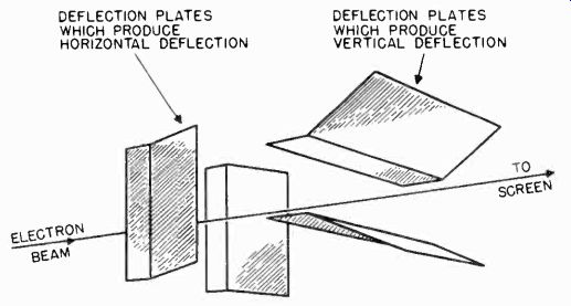
Figure 27. Two pairs of deflection plates mounted at right angles to each
other.
2-24 Electrostatic Deflection. In the description of focusing systems, it was explained that electrons carry a negative charge and are therefore attracted by positively charged bodies and repelled by negatively charged bodies. It follows then that if a positively charged body is brought close to an electron beam, the beam will be drawn toward it and conversely that the beam will be forced away from a negatively charged body. This is the principle upon which electrostatic deflection is based.
2-25 Electrostatic deflection of the electron beam in a picture tube is accomplished by mounting two pairs of metal plates between the electron gun and the fluorescent screen. The pair of plates which deflect the beam vertically are mounted one above the other and are referred to as the vertical deflection plates.
The pair of plates which deflect the beam horizontally are mounted side by side and are known as the horizontal deflection plates.
The designations "vertical" and "horizontal" indicate the direction in which the plates, referred to, move the beam and not to the physical orientation of the plates themselves.
Figure 27 shows two pairs of deflecting plates. The two pairs of plates are mounted at right angles to one another. The ends of the plates nearest the screen are bent outward toward the wall of the tube. This bending is necessary so that the beam will not strike the sides of the plates when it reaches the extreme angles of deflection.
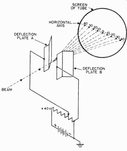
Figure 28. The electron beam is moved horizontally when a d-c potential is
applied to the horizontal deflection plates.
With the plates mounted in the tube, it is only necessary to place a potential across the proper pair of plates to secure vertical or horizontal deflection of the beam.
Figure 29. The horizontal and vertical deflection plates, with separate sources of voltage connected to them.
Figure 28 illustrates a pair of horizontal deflection plates across which a variable potential has been placed. When the potential across the plates is zero, the beam is not deflected and strikes the screen at 0.
If the variable resistor is adjusted toward the positive end so that a 10 volt potential difference exists between the plates, the beam will be deflected and will strike the screen at the point marked 10. The deflection takes place in the direction of plate A because it is the positive plate. If the potential difference is increased to 20 volts, the angle of deflection will be increased, and the beam will strike the screen at the point marked 20. If the voltage is increased to 30 and again to 40, the point at which the electron beam strikes the screen will move to the point marked 30 and then to the point marked 40. If the leads from the battery are reversed so that deflection plate B becomes the positive plate, the beam will be deflected in the opposite direction. By following the procedure previously outlined, the beam can be made to strike the screen successively at the points marked -10, -20, -30, and -40.
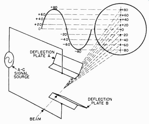
Figure 30. The electron beam traces out a vertical line when a high frequency
sine wave is applied to the vertical deflection plates.
The operation of the vertical deflection plates is identical to that of the horizontal plates except that the plates are mounted one above the other and therefore cause the beam to be deflected up or down. If the upper plate is made positive, the beam will be deflected upward; and if the lower plate is made positive, the beam will be deflected downward.
Figure 29 shows both horizontal and vertical deflection plates.
Separate sources of voltage are shown connected across each set of plates. The horizontal plate A and the vertical plate C are positive and as a result, the beam is deflected upward and to the left simultaneously. If the voltage across the horizontal plates is the same as that across the vertical plates, the beam will move between 1 and 2 in the figure as the voltages are increased equally. The beam can be positioned to any part of the screen by applying deflecting voltages of the correct polarity and amplitude.
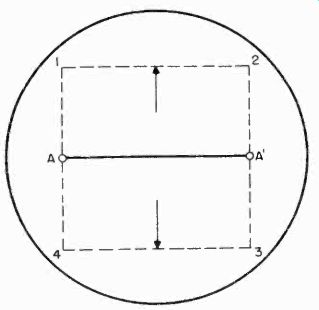
Figure 31. Raster pattern traced out by two sine waves, of equal amplitude,
but of different frequency, which are applied to the vertical and horizontal
deflection plates.
The cathode ray tube is sometimes used as an indicating device to measure voltages. A voltage to be measured is applied to one set of deflection plates. The position to which the spot is deflected on the screen is directly related to the magnitude of the voltage on the deflection plates, and by measuring the distance the spot has moved, the voltage on the plates may be determined.
For television purposes, very rapidly varying voltages are applied to the vertical and horizontal deflection plates. To illustrate the effect of a varying voltage on one pair of plates, Figure 30 shows a sine wave voltage connected to the vertical plates. In a single cycle, the voltage starts at zero, increases to a positive maximum of 80 volts, reduces to zero again, falls to minus 80 volts, and returns to zero once more. With this signal applied to the plates, the electron beam will move under its influence and trace out a vertical line. If the sine wave is of low enough frequency (less than 10 cycles/sec.), the beam will move up and down slowly, and the human eye will detect its movement. If a sine wave of higher frequency is applied (about 60 cycles/sec.), the eye will no longer detect the movement of the beam, and the path traveled by the spot will appear as a straight line on the screen.
If a similar voltage is connected to the horizontal plates of a cathode ray tube, a horizontal line will be traced out by the beam.
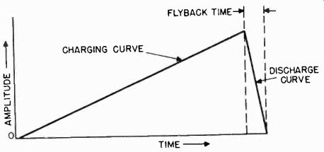
Figure 32. A sawtooth voltage.
If alternating voltages of the same amplitude, but of greatly different frequency, are applied simultaneously to both the vertical and the horizontal deflection plates, the pattern on the screen will no longer be a line, but a square. This may be explained with reference to Figure 31. The line A-A' represents the pattern which is obtained if a varying voltage is applied to the horizontal deflection plates only. Imagine now that another varying voltage is applied to the vertical plates at the same time. The result will be the moving of line A-A' up and down at the frequency of the vertical deflecting voltage. If this frequency is greater than 10 hz, the eye will not detect the movement of the line and the screen will appear to be illuminated over an area bounded by points 1, 2, 3, and 4. The action of the electron beam in tracing out the square pattern is known as "scanning". The illuminated pattern which appears on the fluorescent screen by virtue of this scanning action is known as a "raster".
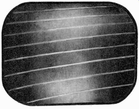
Figure 33. Illuminated pattern produced by applying sawtooth voltages, of
different amplitudes, to the deflection plates.
2-26 Sawtooth Wave. In television, sine wave voltages are not used to secure the scanning action. For reasons which will be apparent later, it is desirable to use a deflecting signal which will move the beam from left to right and then, almost immediately, return it to its original position. The same is true for vertical deflection where it is desirable to move the beam from the top of the raster pattern to the bottom and then return the beam very quickly to the top again. The deflecting voltage which meets these requirements is shown in Figure 32. Such a signal is called a "sawtooth" because of its shape. If such a voltage is applied to the horizontal deflection plates of a picture tube, the beam will move across the horizontal axis at a uniform rate of speed during the rising portion of the curve. The beam will return rapidly to its original starting point when the sawtooth voltage drops back to zero. The time consumed during the return is known as the "flyback time" or "retrace time".
ELECTRONS MOVING INTO PAGE
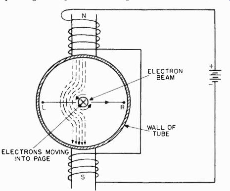
Figure 34. Method of magnetically deflecting the electron beam.
A sawtooth voltage is also applied to the vertical deflection plates. When vertical and horizontal sawtooth voltages act on the beam simultaneously, an illuminated pattern, such as shown in Figure 33, is obtained. This pattern is not square, as that shown in Figure 31, because the vertical sawtooth voltage is not as large as the horizontal sawtooth voltage. Later the part which the sawtooth voltages and the scanning raster play, in creating the television picture on the screen, will be explained.
2-27 Electromagnetic Deflection. Electromagnetic deflection requires the use of coils to influence the beam as does electromagnetic focusing. Figure 34 shows a cross-sectional view of the neck of a picture tube with a pair of solenoids positioned to effect horizontal deflection of the beam. Current flows from the battery through the top coil then through the bottom coil and back to the battery. The coil is split into two parts, each of which is connected in series and placed on a different side of the picture tube. The current through the coil sets up a magnetic field as indicated by the lines of force. In the figure, the electron beam traveling through the center of the tube is going into the page as indicated by the x. The magnetic field, due to the travel of the electron beam, is reinforced by the lines of force from the external field on the left side, while on the right hand side, the fields oppose. This causes the beam to be forced to the right. Similarly, another set of deflecting coils placed perpendicular to the coils, shown in the figure, will deflect the beam up or down, depending upon the direction of the magnetic field surrounding the coils. Since the current through the coils determines the direction of the magnetic field, it also determines the direction in which the beam is deflected.
When magnetic deflection is used, the magnetic field must vary in strength and direction in a manner similar to the varying voltages on the plates of an electrostatically deflected tube. It has been shown that electrostatic deflecting voltages have a saw tooth shape for television scanning. The strength of the magnetic field must also increase and decrease in a sawtooth fashion. Since the magnetic field surrounding a coil is proportional to the current in the coil, the deflecting current will likewise have a sawtooth shape.
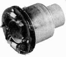
Figure 35. A commercial yoke.
Coils used for electromagnetic deflection consist of many turns of wire and are called solenoids, as in the case of electromagnetic focusing. In order to make a neat and compact arrangement, the vertical and horizontal deflecting solenoids are placed in a cylindrical container called a "yoke". The shape and configuration of the deflection coils in a commercially manufactured yoke are shown in Figure 35.
2-28 Magnetic Focusing vs. Magnetic Deflection. So that the reader will not confuse the action of magnetic fields in focusing the electron beam with the deflecting action, the following is a review of both. In magnetic focusing, the lines of flux around the solenoid placed over the neck of the tube, are parallel to the axis of the tube. A d-c current is fed to the focusing coil to force electrons back to the axis of the electron beam. In magnetic deflection, the lines of flux surrounding the deflecting coils are perpendicular to the axis of the tube. A varying current in the vertical and horizontal deflection coils moves the entire electron beam up and down, or left and right.
The yoke is positioned between the focus coil and the point where the neck joins the funnel portion of the tube, as shown in Figure 36. The electron beam is therefore focused before it reaches the deflection coils. Once the beam has been focused, the deflection coils impart vertical or horizontal motion to it.
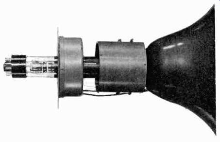
Figure 36. Positions of yoke and focus coils on the neck of a picture tube. (courtesy
DuMont)
2-29 Electromagnetic vs. Electrostatic Deflection. Electromagnetic deflection is preferred over electrostatic deflection when a large diameter picture tube is used. This choice is based mainly on the cost of the circuits necessary to generate the saw tooth voltages or currents which deflect the electron beam. With the larger cathode ray tubes, greater accelerating voltages are necessary in order to obtain a sufficiently intense spot on the fluorescent screen. Since the beam is traveling faster, it is more difficult to deflect. If electrostatic deflection is employed with a large tube, sawtooth voltages of very great amplitude are necessary. It is difficult to build circuits which can generate large sawtooth voltages, while large sawtooth currents can be generated with relative economy. With tubes ten inches and larger in diameter, magnetic deflection is preferred; however, in small tubes, seven inches or less in diameter, electrostatic deflection is used because small sawtooth signals are required to deflect the beam, and the electrostatic system is quite inexpensive. Electrostatically deflected tubes are invariably electrostatically focused. A few magnetically deflected tubes, such as the 5TP4, are electrostatically focused.
2-30 Fluorescent Screens. As mentioned previously, the screen of the picture tube is used to produce a visual pattern of the movement of the electron beam. If a screen were not used in a picture tube, a slight glow would be visible where the electron beam struck the glass face of the tube, even though the beam itself is invisible. The glow would not be satisfactory for viewing purposes and, therefore, a screen material is necessary to produce a bright image on the face of the tube. The screen material used is of such a nature that it glows when bombarded by electrons. Some of the chemicals which react in this manner are zinc orthosilicate, calcium tungstate, and zinc sulfide. The intensity and color of the light emitted by a fluorescent screen depends upon: 1 the chemical used in the coating; 2 the thickness of the coating; 3 the velocity of the electrons striking the coating; 4 the number of electrons which strike the coating (beam current); and 5 the length of time that the beam remains in one position on the coating.
The term "fluorescence" was introduced previously in the discussion of picture tube screens. (Section 2-12). Fluorescence is the property of the screen which causes it to glow when it is bombarded by the electron beam. In describing picture tube screens, the term "phosphorescence" is also used.
Phosphorescence is a property of the screen material which causes it to glow after the electron beam has been removed.
The term "persistence" is used when referring to the phosphorescent property of the screen. A screen which glows for a comparatively long time after being struck by electrons is said to have along persistency, and a screen which glows for a short time is said to have a short persistency. The persistence of the picture tube screen is important in television, since a certain amount of persistence is desirable to make the television pattern appear stationary to the human eye. As the electron beam moves across the screen, it lights up successive points. Because of the phosphorescent quality of the screen material, the points on the screen glow until the beam scans across them again. This enables the eye to retain an image of the spot between successive scans.
Cathode ray tubes are made with screens which have persistencies of from a few microseconds to as long as several minutes. The persistence and color of the glow of screen materials are designated by letters and numbers. For example, a Pl screen has a green fluorescence with a medium persistence.
The P4 screen, used mainly in television, has a white fluorescence and medium persistence. This screen is preferred for television because it produces a black and white picture. Other types of screen are the P7, which has a blue fluorescence and a long yellow phosphorescence, and the P5 and P11 screens, which are blue fluorescent and have a short persistence. The P1, P7, P5, P11, and several other screens are found in tubes used in cathode ray oscillographs.
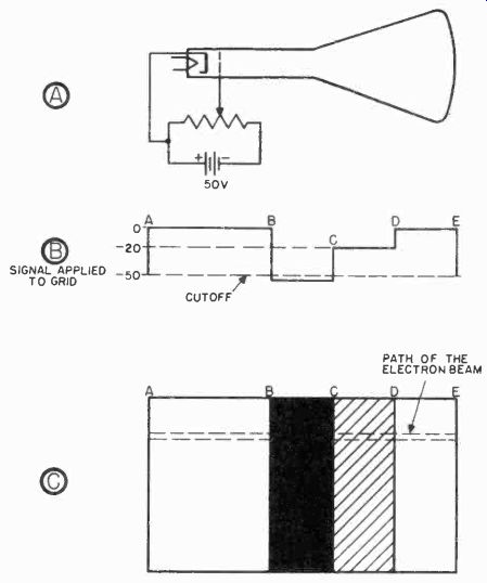
Figure 37. Forming an image on the screen.
2-31 Tube Nomenclature. The nomenclature used for cathode ray tubes has been standardized so that the numbers and letters refer to certain characteristics. The first number -- 5, 7,10, 12, 15, etc. -- indicates the diameter of the screen in inches. This number is followed by a letter A, B, C, etc. which is assigned to indicate the order in which the tube was developed with respect to tubes of the same diameter. Following this letter is the letter P, which stands for phosphor and another number 1, 2, 4, etc. which identifies the type of screen. Examples of picture tubes in use today are the 10BP4, 12JP4, and 15AP4. Illustrating the nomenclature, the 15AP4 tube type has a screen 15 inches in diameter; the "A" indicates that it was the first commercial 15 inch diameter tube to be developed; and the P4 designates the screen as being of the white fluorescent type preferred for use in television receivers.
2-32 Forming an Image on the Screen. If the proper potentials are applied to the elements of the electron gun of a picture tube, an electron beam will be formed. This beam will pass through the tube and strike the screen where, if the beam is properly focused, a small pinpoint of light will appear.
If, in addition to the above, sawtooth signals of sufficient amplitude are applied to the horizontal and vertical deflection plates, a raster will appear on the screen. As described in Section 2-25, a raster is a rectangular pattern of light which appears on the screen when the beam is scanned back and forth and up and down the face of the tube.
In order to form an image on the screen, an additional element of control over the beam is necessary. The number of electrons in the beam must be increased and decreased as the beam moves across the screen. Changes in the number of electrons in the beam will cause some parts of the screen to glow more brightly than others. If the number of electrons in the beam is varied in the proper way, an image will be formed on the screen.
The control, necessary to change the number of electrons in the beam, is provided by the grid. If the potential on the grid is varied, the number of electrons passing through the grid will vary. This function of the grid was described in Sections 2-16 and 2-17.
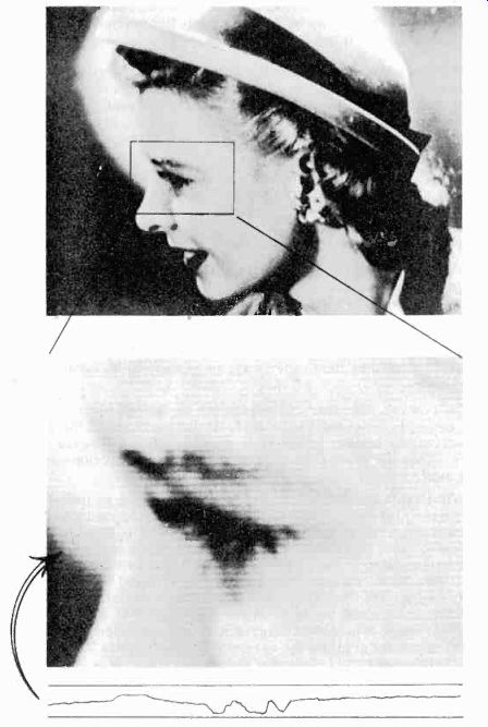
Figure 38. Grid voltage variations necessary to form one line of a picture.
To illustrate the operation of the tube in forming an image on the screen, assume that a battery and a variable resistor are connected to the grid of a picture tube, as shown in Figure 37A. Assume, also, that sawtooth voltages are being applied to the deflection plates and a raster is being formed on the screen of the tube. When the variable resistor is adjusted to place-50 volts on the grid, the electron beam will be completely cut off, and the screen will be dark. When the resistor is adjusted so that no voltage is placed on the grid, a great many electrons will pass through the grid and the screen will glow brightly. At voltages between zero and-50 volts, the screen will glow with varying degrees of brightness, which can be represented as shades of grey.
If, as the beam is deflected across the screen from left to right, the potential on the grid is varied as shown in Figure 37 B, a portion of the pattern shown in Figure 37C will be formed. The portion formed will consist of a thin horizontal line.
As the beam scans across the screen from point A to point B, the potential on the grid is zero and the screen will glow brightly. At the moment the beam reaches point B, the voltage on the grid is reduced to-50 volts. This causes the beam to be completely cut off, and the screen does not glow until point C is reached. At this point, the voltage on the grid is raised to-20 volts. Sufficient electrons reach the screen under this condition to cause it to glow dimly, as represented by the grey portion of Figure 37C. The voltage on the grid remains at-20 volts until the beam is scarped to point D. When point D is reached, the potential on the grid is again zero and the screen glows brightly between points D and E. By this process, one line of the pattern of Figure 37C is formed. When the line has been completed, the action of the saw tooth signal present on the vertical deflection plates moves the beam down slightly. At the same time, the sawtooth signal on the horizontal plates returns the beam, almost immediately, to the left side of the screen. The beam then moves from left to right and another line is formed. This process is repeated until the complete pattern has been formed. All of this takes place in a very short period of time.
It will be remembered that due to the persistence of the screen, it continues to glow after the electron beam has passed over it.
This property of the tube in combination with the persistence characteristic of the eye enables the observer to retain the upper portion of the image while the lower portion is being formed.
After the complete image has been formed, it fades out very rapidly.
The pattern in Figure 37C is a very simple one, but its formation is essentially the same as that of the complex pictures normally encountered in television. Figure 38 shows a complex picture and the grid voltage variations necessary to create one line of it. Note that each line of this picture is different and requires a different group of grid voltage variations to bring about its formation. This is the only difference between the pattern of Figure 37C and the picture of Figure 38.
The picture tube is used in television receivers, where it reproduces scenes transmitted by the television station. Before a scene can be transmitted over the air it must be transformed into an electrical signal. The major part of the task of transforming a scene into a television signal is performed by the camera tube.
THE CAMERA TUBE
Several types of cathode ray tubes have been devised for the purpose of picking up the television picture. The iconoscope is treated first because an understanding of its operation will prove helpful when discussing other types of camera tubes, such as the orthicon, the image dissector, and the mono-scope, which are described in Section 4.
The function of the iconoscope in the television system can be compared to that of the microphone in conventional radio system. The microphone picks up sound and transforms it into an electrical signal. In the television system, the iconoscope picks up light images and transforms them into electrical signals.
The iconoscope is similar in many respects to the cathode ray tube used in the television receiver, and the foregoing discussion of the picture tube applies in many cases to the operation of the iconoscope.
ELECTRON GUN COLLECTOR RINGS ANODE
CONNECTOR TO OUTPUT CIRCUITS COLLECTOR ANODE
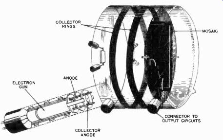
Figure 39. Construction of the Iconoscope.
MOSAIC
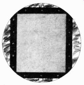
Figure 40. The mosaic of an iconoscope tube.
2-33 Iconoscope Construction. The modern iconoscope, Figure 39, consists of six major parts: a the glass envelope; b the tube base; c the electron gun assembly; d the deflection plate assembly; e the mosaic; and f the collector rings. The tube base, the electron gun assembly, and the deflection plates are the same as those in the picture tube. The shape of the glass envelope is quite different as shown in Figure 39. The important parts of the iconoscope which are not used in the picture tube are the mosaic and the collector rings. The mosaic is a sensitized plate which transforms light into an electrical signal. This signal is passed on to the collector ring, which is a conductive coating on the inside surface of the glass envelope.
2-34 The Mosaic. The mosaic is a mica plate coated with a metal film, as shown in Figure 40. The material used to coat the mosaic is a mixture of chemicals consisting mainly of silver oxide. The mosaic is actually covered with millions of small particles, each of which is insulated from its neighbor.
This structure is obtained by coating the silver oxide on the thin (0.001 inch) mica sheet, and baking the combination in an oven, until the heat transforms the silver oxide into pure silver. During the transformation, the silver forms into tiny particles or globules which are separated from each other by approximately 0.001 inch. the globules are made responsive to light by the addition of cesium vapor. The cesium vapor combines with the silver and forms a thin film around each globule.
The globules when treated in this manner are made responsive to light ("photosensitive"). When a treated globule is exposed to light, it gives off electrons in an amount proportional to the intensity of the light which falls on it. The back of the mica plate, known as the "signal plate," is coated with a conducting material such as aluminum. The aluminum is applied with a brush, spray, or similar method. The mosaic is suspended in the iconoscope by glass members which are molded into the glass envelope. A connection is provided to couple the signal plate to the outside circuit.
ELECTRON MOVEMENT
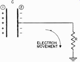
Figure 41. Each globule on the mosaic acts like a condenser.
The shape of the iconoscope tube is such that the electron stream from the electron gun strikes the same side of the mosaic as does the light from the scene being picked up.
2-35 Electrical Operation of the Mosaic. Two theories have arisen to describe how the electron beam, the light rays, and the mosaic function to form a television signal. An understanding of either theory would permit the reader to grasp the fundamental problems in forming an electrical signal from an optical signal. Both explanations will, however, be given here.
In both theories of the electrical operation of the iconoscope, the mosaic and the metal back of the mica plate are believed to act as millions of small capacitors, one plate of each capacitor being common to all of the others. The common plate is the metal backing. Tor the purpose of discussion, it is convenient to visualize one of these small capacitor elements, as shown in Figure 41. When light is focused on the mosaic, each globule emits electrons. The number of electrons emitted depends upon the amount of light to which each globule is exposed; that is, a globule emits more electrons when exposed to a lighter part of the scene than does another globule which is exposed to a darker portion of the scene. In emitting electrons, each globule becomes positively charged. In Figure 41, plate 1, which represents the mosaic, loses electrons and becomes positively charged. This action causes plate 2 to become negatively charged with respect to plate 1. Plate 1 attempts to acquire electrons from the nearest source available in an attempt to become neutral again. The negative plate 2 cannot neutralize the positive plate because of the insulated gap between them.
An electron beam which consists of negatively charged electrons can supply the charges necessary to neutralize the positive side of the capacitor. If an electron beam is allowed to impinge upon plate 1 of the capacitor, the negative charges on plate 2 of the capacitor will be repelled because the electron beam will neutralize or discharge the positive plate 1. The repelled charges, which are electrons, will flow through the resistor R, connected to plate 2. As a result of the current flow, a voltage will develop across the resistor which will be proportional to the original charge on the capacitor. Since the charge was a result of the light to which the capacitor was exposed, the voltage across R is proportional to the amount of light which fell on the capacitor. In this way, light is converted into an electrical potential.
Returning to the mosaic, each globule on the mosaic is a plate of a capacitor. When an image is focused on the mosaic, light rays fall on the globules. The intensity of the light rays falling on any particular globule depends upon the brightness of the part of the scene which is focused on the globule. Thus globules upon which light rays from bright portions of the scene fall, become more positively charged than globules upon which darker portions of the scene are focused.
It will be recalled that an electron gun is mounted in the iconoscope. The electron beam which is created by this gun is made to scan the mosaic in the same manner that the beam in the picture tube scans the picture tube screen. As the beam scans across the mosaic, the electrons in the beam strike each successive globule and equalize the positive charge created by light rays from the scene. As the charge on each globule is equalized, electrons leave the signal plate because it is effectively the opposite plate of a capacitor which has been discharged. The electrons flow through a resistor connected to the signal plate and set up a voltage across it. The voltage changes as the current through the resistor changes, which in turn changes as the electron beam scans across globules which have different positive charges.
The voltage across the resistor consists of a series of electrical impulses which represent the scene focused on the mosaic.
These electrical impulses are the television or "video" signal.
The electron beam which discharges the globules is actually much larger in diameter than a single globule. The diameter of the electron beam is approximately 0.01 inch, whereas the average diameter of a globule is approximately 0.001 inch. When scanning across the mosaic, the electron beam actually discharges many globules simultaneously. The signal which appears across the load resistor is then the average of the charges stored on a number of globules. A group of globules discharged at any one time by the electron beam is referred to as an "element". An element is the smallest area of the mosaic that can be resolved by the electron beam.
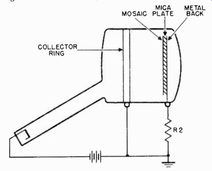
Figure 42. Path of electrons in iconoscope circuit.
In the above explanation, there must be a complete circuit around which electrons flow in order for it to be an accurate account of what happens on the mosaic. To satisfy the necessity for a complete circuit, electrons are said to travel from the electron beam to the mosaic, from the metal plate on the back of the mosaic, through the resistor, through the iconoscope power supply, to the cathode, as shown in Figure 42.
The second theory regarding the electrical operation of the mosaic succeeded the first one after it was learned that the current flowing through the load resistor was many times greater than the number of electrons which fell on each globule. The first theory does not explain where the extra electrons in the output circuit originated. The second theory accounts for this discrepancy and is generally accepted as the more accurate version.
The newer theory continues to assume that the mosaic is made up of tiny capacitor elements which are charged by exposure to light. From this point on, the theories differ.
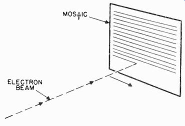
Figure 43. Scanning motion of electron beam across the mosaic.
As the scene being viewed is focused on the mosaic, the photosensitive globules emit electrons. The distribution of the emitted electrons, which accumulate in front of the mosaic, is an electrical reproduction of the scene, greater numbers of electrons being present in bright areas and fewer electrons in the darker areas.
The beam of electrons from the electron gun sweeps over the entire mosaic in a number of successive movements from one side of the mosaic to the other, as shown in Figure 43. each movement or sweep across the mosaic is slightly lower than the previous one until the beam reaches the bottom of the mosaic. At this point, the beam is brought up to the top of the mosaic very quickly and repeats the sweep or "scanning" motion.
As the electron beam scans one globule, the beam strikes the globule with sufficient force to cause additional electrons, called "secondary electrons", to be knocked off the atomic structure of the globule, as shown in Figure 44.
The electrons, which are emitted by the mosaic due to the action of the light which is focused on the mosaic, collect in front of the mosaic in a sort of cloud, or space charge. The number of electrons in front of areas of the mosaic which are exposed to bright portions of the scene is greater than in front of areas exposed to the dark portions of the scene. When the electron beam scans across the mosaic and releases secondary electrons, the electrons in the space charge tend to repel the secondary electrons back to the mosaic. Since the space charge is stronger in front of strongly illuminated areas of the mosaic, fewer secondary electrons will be released from these areas.
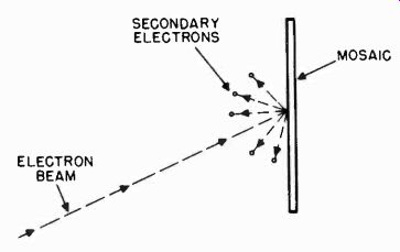
Figure 44. Secondary electrons emitted by a globule on the mosaic.
Thus when the electron beam scans across areas of the mosaic which are highly illuminated, very few secondary electrons are emitted, and when the beam scans across dimly illuminated areas, many secondary electrons are emitted.
The secondary electrons flow to the collector ring through the load resistor where they set up a voltage which varies as the beam scans across light and dark portions of the image. This varying voltage is the video signal.
When a scene is focused on the mosaic, a few of the electrons which are released by photo-emission drift to the collector ring and thence to the load resistor. Since only a few reach the collector ring, the difference in potential between the mosaic and the collector ring is but a few volts. Most of the emitted electrons collect around the mosaic and form the space charge.
When the electron beam strikes a globule, the number of secondary electrons emitted is greatly in excess of those emitted due to light rays from the scene. This largely increased supply of electrons increases the difference in potential between the mosaic and the collector ring. Therefore, when the electron beam is striking globules, a much larger current flows through the load resistor than results from light rays. The variations in current are in exact synchronism with the motion of the electron beam as it passes over each element. The varying current through the load resistor of the iconoscope forms the picture signal which is transmitted to the receiver, and fed to the grid of the picture tube.
2-36 Iconoscope Efficiency. Only a small portion of the total number of electrons emitted by the mosaic find their way to the collector ring and pass through the load resistor. The electrons which leave the mosaic as a result of photo-emission and secondary emission go to one of three places: 1. they travel to the collector ring; 2. they are repelled by the other electrons which have been emitted before them and return to the globule from which they started; and 3. they are repelled by the electrons emitted before them and return to neighboring globules.
It is estimated that only 25% of the electrons which are emitted find their way into the field between the mosaic and the collector ring. Since the potential difference between the collector ring and the mosaic is small, between 15% and 20% of these electrons never reach the collector ring. Therefore, of all the electrons emitted, only 5% or 10% are used in forming the signal.
2-37 Bias Lighting. A method known as "bias lighting" has been developed to increase the efficiency of the iconoscope. As pointed out previously, a great many of the secondary electrons which succeed in escaping from the mosaic do not reach the collector ring because the difference in potential between the mosaic and the collector ring is very small. It has been discovered that many of these electrons collect on the glass wall of the envelope and remain there. The cesium oxide used during the manufacture of the tube not only collects on the mosaic but also on the walls of the envelope. The secondary electrons fall on this cesium oxide surface.
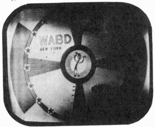
Figure 45. Uneven illumination of the test pattern caused by spurious secondary
electrons in the iconoscope.
The bias lighting method consists of placing small flashlight bulbs in the camera behind the iconoscope. The photosensitive mosaic is not affected by this light source since the bulbs are behind the signal plate. The light from the bulbs falls on the cesium oxide which has coated the inner surface of the glass envelope, and the electrons which have collected on the cesium oxide are released. In this manner, the electrons which were deposited on the walls of the envelope return to the vicinity of the collector ring. Since the electrons carry a negative charge, they increase the potential difference between the surface of the mosaic and the collector ring and increase the efficiency of the iconoscope. While the increase in efficiency is comparatively small, it is important because it increases the sensitivity of the iconoscope. The improvement in sensitivity makes it possible to reduce the intensity of the light on the scene to be televised.
Since the light which must be used is so intense that it is extremely uncomfortable for people to work under, and is also very costly, bias lighting brings about a worthwhile improvement.
2-38 Spurious Secondary Electrons. In addition to its inefficiency, another shortcoming of the iconoscope is the irregularity of illumination it produces on the picture tube in the television receiver. When light is not falling on the iconoscope mosaic, it would be expected that no image signal would appear at the load resistor. Actually, however, a signal does appear and produces the uneven shading shown in Figure 45. When a scene is televised, the uneven shading is superimposed on the picture.
The signals which cause this shading are thought to be secondary electrons which are given off by the mosaic when it is scanned by the electron beam. These secondary electrons accumulate around the mosaic and form an "electron blanket". Many of the electrons emitted during subsequent scannings are repelled by the electron blanket and return to the mosaic. These electrons do not return to their original globules, but "shower" back to others. The result is an uneven distribution of electrons because some portions of the mosaic accumulate more electrons than others. This process takes place whether or not an image is focused on the mosaic. The uneven electron distribution causes different potentials to be set up between the collector ring and various portions of the mosaic. When light from a scene to be televised is focused on the mosaic, the signal voltage developed across the load resistor is a result of the light from the scene, and of the unevenly distributed electrons in the electron blanket.
A way to partially overcome the effects of spurious secondary electrons has been devised. It consists of coupling a signal into the load resistor of the iconoscope to counter balance that portion of the video signal which is a result of spurious secondary electrons. The signal coupled to the load resistor is furnished by a "shading generator". A shading generator produces signals of several different waveforms. The waveform which gives the greatest improvement is selected by the studio technician who monitors the picture.
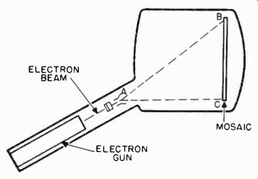
Figure 46. Keystoning occurs in the iconoscope because the electron beam
travels unequal paths from the gun to the mosaic.
KEY STONED PATTERN; UNDISTORTED PATTERN
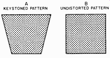
Figure 47. A shows a keystone pattern. B shows correct scanning pattern,
obtained on mosaic when keystone distortion is eliminated.
TOP OF PICTURE BOTTOM OF PICTURE RETRACE TOP OF PICTURE TIME SOLID LINES-HORIZONTAL SWEEP SIGNALS DOTTED LINES-COMPENSATING SAWTOOTH
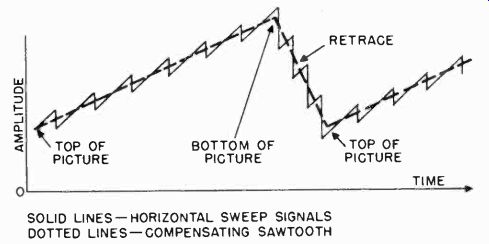
Figure 48. Compensating signal for overcoming keystoning.
2-39 Keystoning. In the iconoscope, the electron beam and the scene being viewed are both focused on the front of the mosaic.
To accomplish this, the electron beam is projected toward the mosaic at an angle. In this way, the electron gun structure is mounted below the mosaic, leaving the area in front of the mosaic clear so that light rays from the scene to be televised can be focused directly on the mosaic. Because the electron gun is mounted in this manner, the electrons in the beam must travel further to reach the top of the mosaic than they do to reach the bottom of the mosaic. This is illustrated in Figure 46 where distance AB is greater than distance AC. Since the beam travels a longer path to reach the top of the mosaic, it has the opportunity to be deflected through a larger horizontal arc than it does at the bottom of the mosaic. As a result, the beam does not trace out a rectangular pattern, but a distorted shape as shown in Figure 47A. This pattern resembles a keystone, and thus the term "keystoning" has been given to the distortion of the image which occurs in the iconoscope.
Keystoning of the image cannot be tolerated since it results in the transmission of a distorted picture. To eliminate the distortion, a compensating signal is combined with the sawtooth voltage which controls the horizontal movement of the beam in the iconoscope. The compensating signal is a sawtooth voltage, as shown in Figure 48. Note that the amplitude of the compensating signal increases as the beam travels downward toward the bottom of the mosaic. Therefore, instead of being constant, the signal which produces the horizontal deflection increases in amplitude as the beam moves downward. When the proper amount of compensation is introduced, the pattern scanned on the mosaic will appear as shown in Figure 47B.
VERTICAL DEFLECTION GENERATOR ELECTRON GUT ViEW. G SCREEN
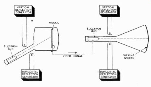
Figure 49. A simplified television system.
A SIMPLIFIED TELEVISION SYSTEM
2-40
In the transmitter and receiver, many tubes and circuits are used to perform the necessary functions of the electronic
television system. While all of these tubes and circuits are important, a clearer understanding of the operation of the television system may be achieved if some of the elements of the system are disregarded and it is assumed that the television system consists of the units shown in Figure 49. Once the operation of the system is understood, the reader will realize the necessity for the additional components and circuits which link and surround the cathode ray tubes in the television camera and receiver.
The simplified system of Figure 49 consists of an iconoscope camera tube, a picture tube, and horizontal and vertical saw tooth deflection generators for both tubes. The mosaic of the camera tube is shown connected to the grid of the picture tube.
By simplifying the television system in this way it becomes much easier to visualize the actions which take place in an actual television system, even though the simplified version is not practical.
Assuming that the system of Figure 49 is in operation but that no image is focused on the mosaic in the camera tube, the following actions are taking place.
1. The electron beam in the camera tube is moving back and forth across the mosaic. At the completion of each excursion across the mosaic the electron beam is moved down slightly to begin scanning another line.
2. The electron beam in the picture tube is moving back and forth across the viewing screen. At the completion of each excursion across the screen the beam in the picture tube is moved down slightly to begin scanning another line. The motion of the electron beam in the picture tube is exactly the same as that of the electron beam in the camera tube.
3. The sawtooth signals applied to the horizontal deflection coils of the camera tube and picture tube are of the same frequency (15,750 cps). The sawtooth signals applied to the vertical deflection coils in both tubes are also of the same frequency (60 cps). Because both horizontal signals and both vertical signals are equal, the electron beam in the camera tube moves in exact synchronization with the beam in the picture tube.
4. The electron beams in both tubes move back and forth, tracing a number of horizontal lines starting at the top of the mosaic and viewing screen and moving toward the bottom. Figure 50 illustrates this process at one instant. Both beams have scanned part of the way down and a number of horizontal lines have been formed. In the illustration, only a few horizontal lines are shown. In an actual television system many more lines are used.
If now an image is focused on the mosaic, several additional actions will take place, as follows.
1. As the electron beam in the camera tube scans across the mosaic, it strikes the globules on the surface of the mosaic and a signal appears at the output of the picture tube.
2. This signal is fed to the grid of the picture tube, where it increases or decreases the number of electrons in the electron beam.
3. As the electron beam in the camera tube strikes globules of the mosaic on which a bright portion of the scene being televised is focused, the signal at the output of the tube increases.
MOSAIC VIEWING SCREEN
CAMERA TUBE PICTURE TUBE
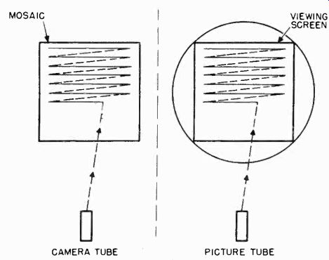
Figure 50. The electron beam scans the mosaic in exact synchronism with the
electron beam in the picture tube.
4. When the increased output of the camera tube reaches the grid of the picture tube, it causes the number of electrons in the beam to increase, and thus the screen glows more brightly.
5. As the electron beam in the camera tube strikes globules on which dark portions of the scene are focused, the output to the picture tube decreases, and the number of electrons in the picture tube beam decreases. As a result, the portion of the viewing screen being scanned glows dimly. The positions of the bright and dark portions of the mosaic always correspond to the bright or dark portions of the viewing screen, because the electron beams in the camera and picture tubes are always in the same relative positions.
6. When the electron beams have reached the bottom of the mosaic and viewing screen, a complete image will appear on the viewing screen. This image is a reproduction of the image focused on the mosaic. The scanning action takes place so rapidly that the persistence of the eye (Section 1) and of the screen coating cause us to see a complete image whose structure of lines and elements is barely visible.
7. In order to create the illusion of motion, images are created on the viewing screen in rapid succession. Each image is slightly different than the one preceding it. Successive images are created so rapidly that the eye blends them into one continuously changing picture.
SCANNING
2-41 The method used in the television system, to break down a picture into a series of horizontal lines, which are made up of a series of elements, has been described previously. These horizontal lines appear, to the eye, to blend into a uniform picture if they are presented in very rapid succession. The mechanical television systems which preceded the electronic system were capable of breaking a picture into 60 horizontal lines.
The quality of pictures produced by these systems was very poor because not enough elements could be presented by 60 lines.
The number of lines, into which the mechanical system could break a picture was limited by the speed at which the scanning disc could rotate. The electronic television system which employs cathode-ray tubes overcomes this scanning problem. In the iconoscope and picture tube, the picture is scanned by an electron beam which is practically Inertialess. The beam can be made to scan any number of horizontal lines by applying deflection signals of suitable frequency to the vertical and horizontal plates. In the present electronic television system, the number of lines has been standardized at 525 for each complete image. As will be described later, it is not possible to increase the number of lines above this number because of the limitations that have been placed on the channel assigned to each television station. In the following paragraphs the quality and characteristics of the television pictures, which can be obtained with a 525-line system, are discussed.
2-42 Aspect Ratio. The television picture has been designed to have a height 3/4 its width as shown in Figure 51. The ratio of the height of a picture to its width is known as its aspect ratio. The aspect ratio of the standard television picture is therefore three to four. This aspect ratio is used because it has been found, by tests on many persons, to be the most pleasing to the eye, for long viewing periods.
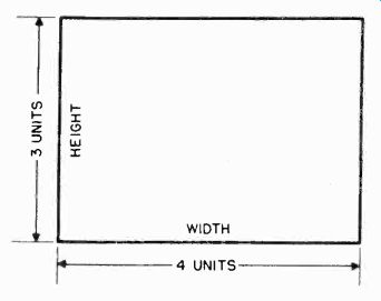
Figure 51. A pattern with a 3 x 4 aspect ratio.
2-43 Picture Elements vs. Bandwidth. The number of elements into which a television system breaks a picture has a direct relation to the width of the channel occupied by the television signal, when' it is transmitted over the air. Since the radio frequency spectrum is quite crowded, bandwidth has been the factor which has limited the number of elements in the standard picture. If space were available in the spectrum, it is very probable that the number of lines and elements in the television picture would be greater than at present.
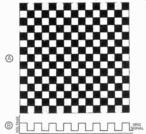
Figure 52. A, checkerboard pattern. Each black and white square is assumed
to represent an element in a picture. B, grid voltage which is required to
produce checkerboard pattern on the screen of the picture tube.
The reader will understand the relationship between bandwidth and the number of elements in the picture by referring to Figure 52A. Assume that the number of checkered squares in the figure is increased until the maximum number, which a 525 line television system can reproduce, is reached. The number of squares in the figure will then be equal to the number of elements into which the system is capable of breaking an image.
Since the elements are square, the height and width of each element will be equal to the width of one horizontal line. In the 525 line picture, there will be 525 elements in a vertical line running from the top to the bottom of the picture. If the aspect ratio is the same as the standard, three to four, there will be 700 elements along each horizontal line (4/3 x 525). In order to reproduce such a picture on the screen of a picture tube, the signal on the grid of the picture tube would have to be similar to that shown in Figure 52B. As the electron beam scans across each horizontal line, the signal on the grid would have to increase and decrease for each white and black element.
For the 700 black and white squares on one line, there would be 350 cyclic changes from white to black. In other words, the television transmitter would have to transmit 350 pulses or cycles for each line. Each time a pulse is received and applied to the grid of the picture tube, it increases the number of electrons in the electron beam and the screen glows brightly. At the end of each pulse, the signal on the grid drops and the number of electrons in the beam decreases enough so that the screen is almost completely black. When the next pulse arrives, the process is repeated. Note that for every two picture elements, the signal on the grid must go through one cycle of change.
If one line requires 350 cycles of change, then 525 lines require 525 x 350, or 183,750 cycles. Assuming that the picture is formed in one second, the frequency of the video signal would be 183,750 cps.
If one complete picture, containing 525 lines, was presented to the eye each second, the eye would notice flicker as the elements were traced out line by line, for it will be recalled that at least 10 complete pictures per second must be presented to the eye to prevent flicker. To remove all traces of flicker, as many as 48 pictures are presented each second in motion pictures (24 frames, each projected twice.) In television, as many as 60 pictures are used. The 60 cycle repetition rate of television pictures has been chosen because it equals the frequency of most of the power lines in this country. This is a distinct advantage as the reader will realize when he familiarizes himself with the operation of receiver deflection circuits.
Returning to the checkerboard pattern which would produce 183,750 cycles of voltage for each complete picture scanned by the electron beam, it is apparent that there would be 183,750 x 60 or approximately 11,000,000 cycles per second if 60 pictures were scanned per second. The television channel would have to be 11 megacycles wide if all the shades in the checkerboard pattern were to be reproduced faithfully.
Because it has been impossible to assign an 11 megacycle channel to each television station, several methods have been developed to decrease the frequency of the video signal that is required for a 60 frame television system.
2-44 Interlaced Scanning. Two ways have been devised to reduce the band occupied by the video RF signal, and at the same time maintain the picture quality possible with a 525 line, 60 frame per second system. The bandwidth is reduced through the use of interlaced scanning and single sideband transmission.
Interlaced scanning is discussed here, while single sideband transmission is discussed later in this section. The reader should keep in mind the following points in order to understand what it accomplishes.
1. The purpose off interlaced scanning is to reduce the number of voltage cycles per second (frequency) of the video signal and thus reduce the band occupied by the video RF signal.
2. It is desirable to accomplish this and still retain the picture quality of a 525 line, 60 frame per second system.
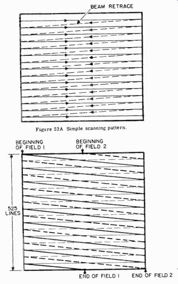
Figure 53A Simple scanning pattern. Figure 53B Interlaced scanning pattern.
3. The frequency of the video signal is directly related to the number of lines in each frame and to the number of frames transmitted each second. A reduction in either the number of lines in a frame or in the number of frames transmitted each second will reduce the frequency of the video signal.
To understand interlaced scanning, consider first a simple scanning system in which the electron beam traces out 525 horizontal lines. An example of this method of scanning is illustrated in Figure 53A. The electron beam starts at the top left hand corner and moves across the picture to the. right side. The beam then quickly snaps back to the left side and scans the line below. This process is repeated for 525 lines. At the end of the 525th line the beam is at the bottom right hand corner of the picture. With this method of scanning, the beam would trace out 525 lines, 60 times per second.
In the interlaced scanning system the electron beam does not trace out the 525 lines in succession. Instead it skips every other line, tracing out first the odd number lines. When the beam reaches the bottom of the picture, it returns to the top and scans only the even number lines. This method of scanning is shown in Figure 53B. To scan a complete 525 line picture or frame, there are two complete scans or fields. One field contains only the odd number lines and the other field contains only the even number lines. The field repetition rate is 60 cycles per second, but now the picture or frame repetition rate is 30 cycles per second. In other words, two fields containing 262.5 lines each are required to make up a 525 line frame.
The effect of the interlaced scanning system is to deceive the eye into seeing 60 complete pictures or fields per second. The eye blends the odd line fields and the even line fields into a 525 line picture occurring only 30 times per second. The interlaced scanning system is thus very similar to the movie projection system in which 24 frames per second are used, but each frame is projected twice. To the eye it appears that 48 frames are projected each second.
With the interlaced scanning system 30 x 183,750 or approximately 5,500,000 cycles per second must be transmitted to reproduce the checkerboard pattern. The bandwidth is reduced to one half that required with the simple scanning system which presents 60 complete pictures containing 525 lines each. The reduction in bandwidth is accomplished without increasing the flicker effect, because 60 fields of 262.5 lines each are presented using the interlaced system.
The 5.5 megacycle band required for transmitting an interlaced picture is even more than can be allocated to any one television station. As a compromise between the desired number of elements in a picture and the limits of the space in the frequency bands allotted to television, the video signal is limited to 4 megacycles.
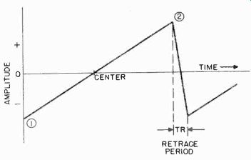
Figure 54. Sawtooth scanning voltage.
2-45 Scanning Signals. To understand interlaced scanning thoroughly, the reader should be familiar with the type of pattern produced by the signals which move the electron beam in the iconoscope and picture tube and cause it to trace out the scanning pattern. The electron beam scans the top line of the mosaic from left to right, returns to the left side of the mosaic skips the second line, and scans the third line as shown in Figure 53B. This process is repeated until the electron beam reaches the bottom of the picture. In tracing out the pattern the beam moves horizontally and vertically. The horizontal motion of the beam in scanning the mosaic is quite rapid, whereas the vertical motion is considerably slower. The signals which are applied to the deflection plates (or coils) of the iconoscope and picture tube to produce the scanning motion are of the sawtooth variety. Figure 54 is a graphic illustration of the sawtooth waveform. The voltage starts at a negative value, increases along a straight line to the zero level (at which point the electron beam is at the center of the mosaic), continues along the straight line to a positive value equal in amplitude to the voltage at which the beam started, and then quickly returns to the initial negative value. If this sawtooth voltage is fed to the horizontal deflecting plates, the electron beam will be deflected from the left side of the mosaic to the right side, return rapidly to the left side, and begin moving across the mosaic again. In each field, using interlaced scanning, there are 262.5 horizontal motions of the beam to one vertical motion of the beam. Therefore a sawtooth voltage of much lower frequency; than the horizontal deflection signal, is applied to the vertical plates to move the beam vertically.
An important characteristic of the sawtooth scanning voltage, shown in Figure 54, is the uniformity, or "linearity", of the voltage rise between points 1 and 2. If the rate were not constant, the electron beam would not move across the mosaic at a uniform speed. This would result in a distorted picture, as shown in Figure 55. A picture distorted in-this fashion is said to be non-linear. A non-linear picture is caused by a sawtooth voltage which has the shape shown in Figure 56. The rising portion of the sawtooth is bent, or non-linear.
It is desirable to keep the time required for the beam to snap back from the right side of the mosaic to the left side as small as possible. In practice this would mean that the portion of the sawtooth voltage represented by Tr in Figure 55 be straight up and down. Unfortunately the circuits necessary to achieve such a condition are too costly to be practical. In practice, the time Tr is generally limited to about 10% of the complete sawtooth waveform.
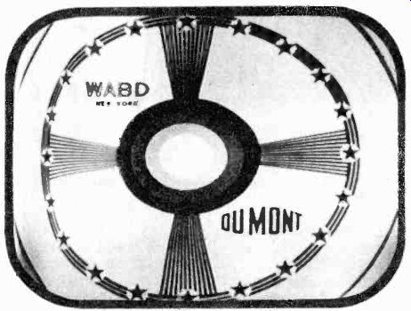
Figure 55. Horizontal distortion of test pattern caused by nonlinear scanning.
As mentioned previously, each complete field is scanned 60 times per second. Therefore, the frequency of the sawtooth voltage on the deflection plates which move the beam vertically is 60 cps. In each field there are 262.5 horizontal lines. Therefore, the frequency of the sawtooth voltage on the horizontal deflection plates is 262.5 x 60, or 15,750 cps.
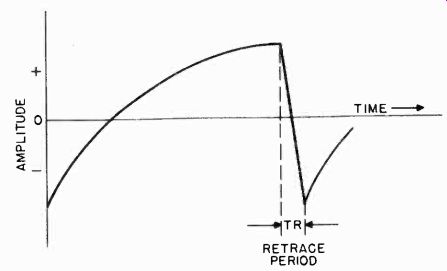
Figure 56. Shape of sawtooth voltage which produces non-linear pattern shown
in Figure 55.
2-46 Interlaced Scanning Pattern. Figure 57 illustrates an interlaced scanning pattern. As the horizontal deflecting voltage moves the beam from point 1 to point 1B, the vertical deflecting voltage simultaneously produces a small downward movement of the beam. When point 1B is reached, the beam snaps back to point 2 and scans to point 2B. This process continues until the bottom of the mosaic is reached and the 262nd line is scanned. At the completion of the 262nd line, the beam returns to the left side of the mosaic and starts to trace line 263. It reaches the bottom of the mosaic when halfway through line 263.
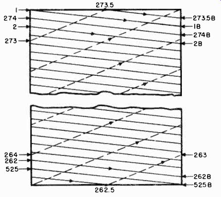
Figure 57. Method of forming interlaced scanning pattern.
When the beam reaches the middle of line 263, the vertical deflecting voltage has reached its peak and commences the vertical retrace. During the vertical retrace period, the beam moves from the bottom of the mosaic back to the top. At the same time, the horizontal deflecting signal continues to move the beam back and forth across the mosaic. Since the retrace time of the vertical deflecting signal is quite short, the beam moves up the mosaic quite rapidly from points 263 to 264 to 265, and finally from 273 to 273.5. These lines which occur during the vertical retrace period are visible on a picture tube screen when no signal is being received. Point 273.5 corresponds to the beginning of the next vertical sawtooth deflecting signal, and the beam is displaced exactly halfway across the mosaic from point 1 where the first scanning line started. The process starts all over again with the beam moving from point 273.5 to point 273.5B of the second field. The lines in the second field fall between the lines in the first field because of the half line displacement at point 273.5. The last line scanned in the second field is from point 525 to point 525B. At this point the vertical sawtooth deflecting signal retraces again and the electron beam starts scanning downward once more from point 1.
In this system of interlaced scanning, some of the horizontal lines are wasted during the interval that the vertical sawtooth deflecting signal is retracing. About 12.5 horizontal lines are wasted in each field. For two fields, or one frame, 25 lines are wasted. In practice. then, for one complete frame, instead of obtaining a picture of 525 horizontal lines, only 500 lines are actually seen. Since the retrace portions of the horizontal and vertical deflecting signals are not used to convey picture information, the electron beam is automatically cut off during the retrace period.

Figure 58. Retrace lines which would be visible if they were not obliterated
by blanking pulses.
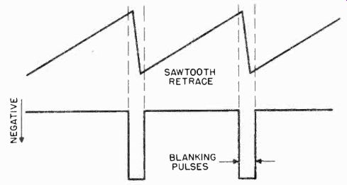
Figure 59. Waveshape and polarity of blanking pulses.
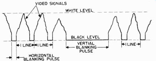
Figure 60. A composite video and blanking signal.
2-47 Blanking Pulses. The scanning lines produced during the vertical and horizontal retrace periods contribute no useful information to the picture, and produce unwanted bright lines in the picture, as shown in Figure 58. The retrace lines are, therefore, obliterated by cutting off the electron beam during the retrace periods. This is accomplished by feeding negative pulses to the grid of the iconoscope at the end of each line and at the end of each field. These pulses have the wave shape shown in Figure 59. The duration of each pulse is slightly longer than the retrace time of the sawtooth signals. When the negative pulse is applied to the picture tube grid, the grid becomes so negative with respect to the cathode that no electrons pass through the grid aperture. This controlling feature of the grid electrode was discussed previously under the section on cathode-ray tubes. The method of preventing electrons from passing through the grid during the retrace time of the sawtooth deflecting signals is called "blanking", since the negative pulses effectively blank out the electron beam. The negative pulses which cause blanking of the beam are called blanking or pedestal pulses. The blanking pulses are generated at the television station where they are applied to the iconoscope grid to provide blanking. The pulses are also mixed with the signal output from the iconoscope. A television signal with blanking pulses added is shown in Figure 60. The blanking pulses drive the video signal down to the blank level which corresponds to the grid cut-off bias of the tube. Note that a longer blanking pulse is required for the vertical blanking than for the horizontal blanking. This is because the retrace time of the vertical sawtooth voltage is longer than that of the horizontal sawtooth voltage. These blanking signals appear at the television receiver where they are fed to the grid electrode of the picture tube.
2-48 Synchronizing Pulses. It was assumed in the foregoing discussion that the deflecting signals which cause the beam to move horizontally and vertically were of a constant frequency.
HORIZONTAL SAWTOOTH VOLTAGE- 15,750 hz
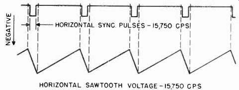
Figure 61. Horizontal sync pulses occur during retrace period of horizontal
sawtooth voltage.
The circuits used to generate sawtooth signals, however, have a tendency to change frequency, or "drift". Because of the inherent frequency drift of such circuits, the sawtooth scanning voltages in the iconoscope may differ slightly in frequency from the sawtooth voltages which control the scanning of the beam in the picture tube. The picture tube scanning beam would then be out of synchronization with the iconoscope scanning beam and would not reproduce the television picture in the same sequence in which it is being scanned in the camera tube.
To keep the frequency of the deflecting signals constant at the transmitter and the receiver, additional signals are fed to the iconoscope sawtooth generator circuits from a synchronizing generator which puts out synchronizing pulses of constant frequency. These synchronizing pulses are mixed in with the video signal and the blanking pulses.
Separate sync pulses are necessary for proper operation of both the horizontal and vertical sawtooth deflecting circuits. At the transmitter these signals are generated, mixed in the proper sequence, and fed to the iconoscope deflection circuits. Special circuits separate the horizontal sync pulses from the vertical sync pulses. The separated horizontal sync pulses are then used to synchronize the horizontal sawtooth voltages while the vertical sync pulses lock the vertical sawtooth voltages. At the receiver, the synchronizing pulses are removed from the combined signal and fed to the sawtooth generators, to maintain their frequencies in step with the sawtooth generators at the transmitter.
The horizontal sync pulses have a square wave shape as shown in Figure 61, and occur at a frequency of 15,750 hz, which is, of course, the same frequency as the horizontal sawtooth scanning voltages. The vertical sync pulse must occur once each field to synchronize the vertical sawtooth voltage, and therefore has a frequency of 60 cps. The shape of the vertical sync pulse is shown in Figure 62. It is actually made up of six small pulses.
The vertical sync pulse is formed in this manner to provide synchronization of the horizontal sawtooth generator during the vertical retrace period. This synchronization problem is discussed in greater detail in Section 3.
The sync pulses do not convey picture information. They are merely "keying" signals which are used at the transmitter, and the receiver, to synchronize the sawtooth scanning circuits.
VERTICAL SAWTOOTH VOLTAGE--60 hz
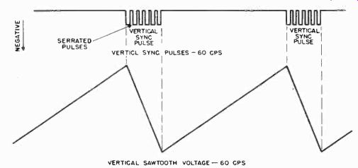
Figure 62. The vertical sync pulse consists of six serrated pulses.
These sync pulses could be fed to the iconoscope deflection circuits and then transmitted to the receiver as a separate radio signal. It is much simpler however, to combine the sync signals with the video and blanking signals and transmit them simultaneously. The method by which the signals are combined is explained with reference to Figure 63. The synchronizing pulses are added to the blanking, or pedestal, pulses. The term pedestal pulse is used synonymously with blanking pulse because the blanking pulse serves as a base, or pedestal, upon which the sync pulses are set. Since the blanking pulse must drive the grid of the iconoscope and receiver to cutoff, it represents the black level (the video signal level which produces black on the screen). The sync pulses, being even more negative than the blanking pulses, occur only during the retrace periods when the beam is cut off. The sync pulses cannot, therefore, produce any visible illumination on the screen. They are thus conveniently sent along with the picture information to synchronize the deflection circuits at the receiver with those at the transmitter.
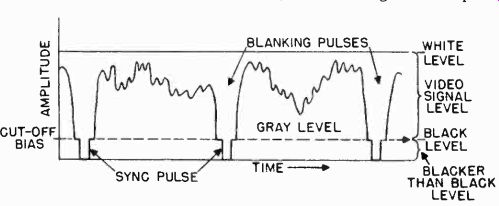
Figure 63. Combined sync, blanking, and video signals.
2-49 The Television Signal. Thus far three signals, video, sync, and blanking, have all been mixed together to form the "composite" television signal. Figure 63 shows two horizontal lines of video signal with blanking and sync pulses between them.
The maximum amplitude of the signal in the positive direction corresponds to the "white level" (the video signal level producing white on the screen). The "black level" is the bottom of the picture information. This level corresponds to the amplitude of the blanking pulse. At this level the beam is cut off and no illumination of the screen occurs. The sync pulses extend below the black level. *The region occupied by the sync pulses is called the blacker than black level or super-sync.
A television signal, such as shown in Figure 63, in which the maximum signal amplitude corresponds to the white level, is said to have a positive polarity. This is the polarity of the signal required at the grid of the receiver picture tube to reproduce the proper shades in the picture, because as the amplitude of the signal is decreased, the voltage on the grid becomes more negative, and the illumination on the screen changes from white to shades of gray. When the signal drops to the blanking or black level, the voltage on the grid is sufficiently negative to cut off the beam and the screen appears black.
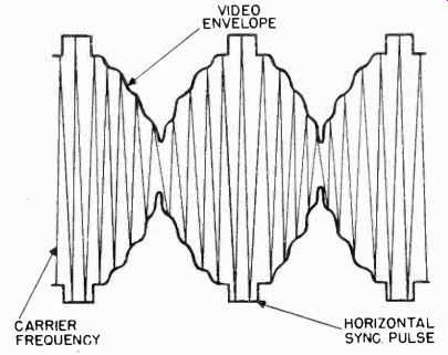
Figure 64. Radio-frequency carrier modulated by the composite video signal.
The polarity of the video signal is said to be negative because maximum amplitude
of the carrier corresponds to the tips of the sync pulses.
When the television signal is transmitted on an RF carrier, it has a negative polarity, as shown in Figure 64. The negative polarity is desirable because it makes the picture signal more immune to noise. Noise bursts usually effect only the upper and lower limits of the modulating signal. With negative transmission, noise signals are superimposed on the sync signals and occur during the "blacker than black" level, when the electron beam is cut off in the picture tube. In this way the noise does not interfere with the picture information. At the receiver, the polarity of the signal is changed from negative to positive before it is applied to the grid of the picture tube.
2-50 Equalizing Pulses. In addition to the horizontal and vertical sync pulses, another group of pulses is required when interlaced scanning is used. With interlaced scanning, the even scanned lines lie midway between the odd-scanned lines. This interlacing of lines takes place because of the half-line displacement at the end of one field and the beginning of the next field. This means that the vertical sawtooth voltage of one field must occur one half line later than the preceding vertical saw tooth. Since the vertical sawtooth voltages are "keyed" by the vertical sync pulses, it is necessary to make the vertical sync pulses occur one half line after the last horizontal sync pulse in one field, and one full line after the last horizontal sync pulse in the next field. The half line difference in time of the vertical sync pulse with respect to the horizontal sync pulses in two successive fields is brought about by several half line pulses known as equalizing pulses. These pulses occur at twice the frequency of the horizontal sync pulses (or every half line). One group of six equalizing pulses precedes the vertical sync pulse, while another group follows it. Elsewhere in this section the manner in which the equalizing pulses account for the half line displacement is discussed.
2-51
Picture Qualities. In discussing the qualities of a television picture, three terms are used: (1) resolution, (2) contrast, (3) brightness. The term resolution is used to describe the amount of detail that is visible in various objects in a television picture. In this sense, resolution refers to details in both the horizontal and vertical directions.
DIAMETER OF HORIZONTAL LINES IN ELECTRON BEAM PICTURE TO BE REPRODUCED
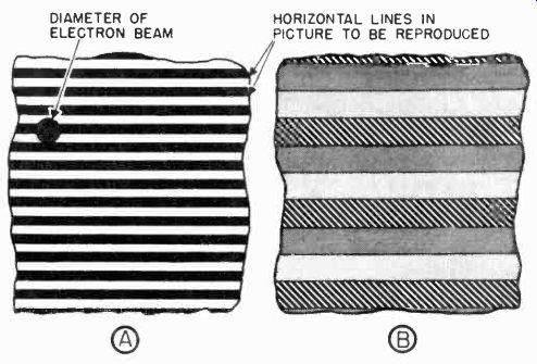
Fig. 65 Magnified portion of a picture containing 1,000 horizontal black
lines.
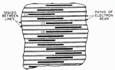
Figure 66. Magnified portion of the mosaic showing scanning lines and pattern
of horizontal black lines projected on the mosaic.
2-52 Vertical Resolution. The significance of vertical resolution may be appreciated by a study of the pattern in Figure 65A. This pattern is a magnified portion of a picture which consists of 1,000 horizontal lines, each alternately black and white. The circle represents the diameter of the electron beam in the iconoscope or picture tube. The beam is larger than the thickness of one line. Therefore, when the beam scans the pattern, it cannot distinguish the sharp demarcations between the black and white lines. The signal from the iconoscope mosaic results from a combination of globules, some of which have been exposed to white, and some to black. The beam, in discharging a group of these globules, produces a voltage which represents a mixture of black and white. On the picture tube the pattern does not appear as sharp black and white lines, but as varying shades of grey. See Figure 65B. In order to reproduce the pattern as black and white lines, the electron beam must have a diameter much smaller than the thickness of the horizontal lines in the picture being televised.
Otherwise, the beam cannot transform, or resolve, fine details in the vertical direction. To obtain the maximum resolution possible with the present 500 line system, the beams in the iconoscope and in the picture tube must be focused to very small spots. It is essential that the electron beams in the camera and picture tubes be sharply focused at all times, for the vertical resolution is limited by the size of the spots which the electron beams make on the mosaic and on the picture tube screen.
Another factor affecting the vertical resolution of a television system is the number of lines into which it breaks a picture.
Figure 66 represents a magnified portion of a mosaic showing the path of the electron beam as it scans 525 horizontal lines.
Also shown are a number of horizontal black lines which are projected on the mosaic from a pattern. These horizontal black lines (1, 2, 3, etc) are so thin that they fall between adjacent scanning paths of the electron beam. The black lines, therefore, do not contribute to the signal output obtained from the iconoscope and hence will not appear on the receiver picture tube. Thus, the number of scanning lines in the television system also limits the vertical resolution. The greater the number of lines a television system breaks an image into, the greater is the vertical resolution which can be obtained.
VIDEO HANDBOOK
Since the number of horizontal lines in the present television picture is fixed at 500 (525 less the 25 horizontal lines that are lost during the vertical retrace time), the maximum possible resolution is predetermined.
2-53 Horizontal Resolution. Horizontal resolution is a measure of the ability of the television system to distinguish between closely spaced vertical details, such as lines. Here again, the diameter of the electron beam is a limiting factor. Horizontal resolution is also limited by bandwidth of the transmitter and receiver circuits, and the channel occupied by the video RF signal. The reader will recall that the number of elements in the checkerboard pattern which can be reproduced along one line is determined by the bandwidth of the video signal. Since the signal must pass through a number of amplifiers in both the transmitter and receiver, the bandwidth of these amplifiers is an important factor affecting the horizontal resolution. As a rule, the circuits in transmitters are sufficiently broad to pass the full band of video signals. This is also true of the higher priced television receivers, but in many low cost receivers the bandwidth of the IF amplifiers is not great enough to pass the complete video signal. In this case, the IF amplifiers become the factor in the system which limits the horizontal resolution.
In small picture television receivers (7 inch or smaller picture tubes), the horizontal resolution is primarily limited by the spot size. The images available on the small screens of these tubes are approximately 4 x 5 inches and less. When 500 horizontal lines are crowded into this small area, the lines are so close together that an extremely small spot size is necessary.
The picture tubes used are not capable of producing a spot size small enough to take advantage of the horizontal resolution capabilities of the rest of the system. Since the spot size of the beam limits the number of individual elements that can be reproduced along one line in the horizontal direction, there is little point in employing 4 Mhz. amplifiers in receivers using small picture tubes, since the vertical and horizontal resolution is already limited by the size of the picture and the diameter of the electron beam. An amplifier response of 2.5 Mhz. is considered sufficient for use with small picture tubes.
It should not be inferred from the above that all small tubes produce comparatively large spots. The size of the beam can be reduced by making the hole in the grid smaller and by increasing the accelerating voltages. This is actually done with small projection tubes which throw the television image onto large screens by means of optical systems.
2-54 Contrast. Contrast refers to the relative intensity of the light and dark areas in a picture. The television pattern of Figure 67A lacks sufficient contrast and therefore appears flat.
Figure 67B shows a pattern having too much contrast, and Figure 67C shows a pattern which has proper contrast.
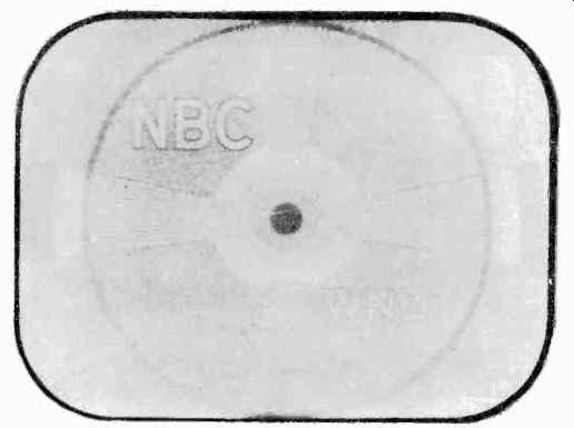
Figure 67A Insufficient contrast.
At the transmitter it is possible to control the contrast by boosting the amplitude of the video signal picked up from the iconoscope. At the receiver the contrast can be controlled by changing the amplification of the video signal in the receiver circuits.
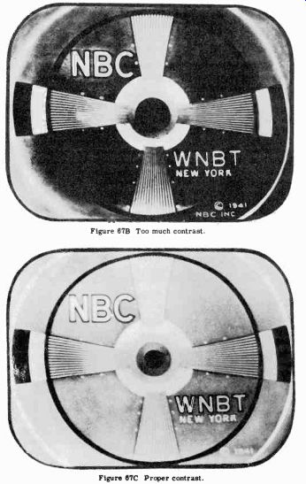
Figure 67B Too much contrast. Figure 67C Proper contrast.
2-55 Brightness. Whereas contrast is a measure of the relative intensity of the light and dark areas in the picture, brightness represents the average intensity of the overall picture.
Brightness is controlled at the television receiver by varying the d-c voltage on the grid of the picture tube. The d-c voltage changes the number of electrons flowing to the screen and, therefore, the average illumination.
Figure 68A A typical test pattern.
2-56 Test Patterns. In order to facilitate the adjustment of television transmitters and receivers, test patterns are usually transmitted by television stations for several hours during the day.
A typical test pattern is shown in Figure 68A. By observing the test pattern image obtained on the receiver picture tube, several of the characteristics of the overall television system can be determined. Horizontal resolution can be determined by noting how far in toward the inner circles of the "bulls-eye" the lines in the vertical wedge are resolved. If the lines are distinctly black and white for their entire length, the picture is said to have 350 line horizontal resolution. If the horizontal resolution is poor, then the vertical lines become blurred near the inner circles and the resolution is less than maximum, as indicated by the numbers on the chart. The vertical resolution is measured similarly by observing how far toward the inner circle the lines in the horizontal wedge can be resolved. Figure 68B shows a test pattern having poor resolution. Note that the fine lines in the wedges are not distinctly visible.
The degree of contrast of the television system can also be determined by the use of the test pattern. The inner circles in Figure 68A range from complete black in the center, through several shades of grey, to the white background of the pattern.
Good contrast in a picture is indicated by distinct changes of shade between each circle.
Figure 68B Test pattern with poor resolution, as it appears on screen of
picture tube.
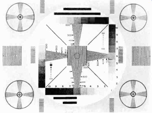
Figure 69. RMA test pattern.
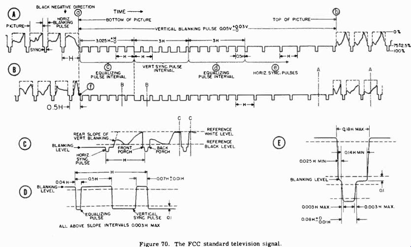
Figure 70.
2-57 RMA Test Pattern. The Radio Manufacturers' Association has proposed that the test pattern shown in Figure 69 be used as a standard pattern for test purposes. In addition to enabling checks of contrast and resolution to be made, this test pattern provides a means for determining the proper operation of other circuits in the television transmitter and receiver with respect to scanning, brightness, phase shift, focus, plus several other factors. A complete explanation of the RMA test pattern will be found in Section 9.
2-58 The FCC Standard Television Signal. The wave shape of the composite television signal has been standardized by the FCC, so that all stations may transmit uniform waveforms to which all receivers can synchronize. Figure 70 shows the composite video signal, near a vertical synchronizing pulse, for two successive fields. Although this diagram appears complex, it can be readily interpreted by careful study.
2-59 Amplitude Characteristics. The percentage amplitude levels of the various components of the video signal have been standardized to enable proper operation of the receiver. Assuming the peak-to-peak amplitude of the composite signal to by 100%, Figure 70A indicates that 75% plus or minus 2.5% of the maximum amplitude is devoted to the picture information contained in the camera signals. The remaining 25% is occupied by the synchronizing pulses. It will be remembered that the blanking level represents black (or grid cutoff) on the cathode ray tube. This makes a convenient reference point to which various shades in the picture can be related; hence at the transmitter, the blanking level (and the synchronizing pulses) are always kept at the same percentage modulation point.
2-60 Frequency Characteristics. The time duration of the various pulses is indicated in percentages of H and V. H equals the time from the start of one line to start of the next line or 63.5 microseconds 1 second) (15,750 V equals the time from the start of one field to the start of the next field or 16,667 microseconds( 1 second)
Five waveforms are shown in the figure, as follows: A. Figure 70A shows:
1. The vertical blanking interval extending between points a to b, for a period of 0.05V, or about I4H. 60 vertical blanking pulses occur per second.
2. Superimposed on the vertical blanking pulse are six equalizing pulses (c), extending for 3.025H.
3. Following the first equalizing pulses is the vertical sync pulse, lasting for 3H. The vertical sync pulse has 6 slots, or serrations, to provide continuity of horizontal synchronization during the vertical blanking interval.
4. Six more equalizing pulses (d) follow for a time equal to 3H. The equalizing pulses have a frequency twice the rate of the horizontal sync pulses, and therefore occur 0.5H apart. They are so positioned in the vertical blanking interval as to provide for the half line difference between fields and permit interlaced scanning.
5. Several horizontal pulses (e) occur after the equalizing pulses before the vertical blanking period ends. Each horizontal pulse occurs once each line, and of course, is spaced H time apart.
6. At the end of the vertical blanking interval (b), the cathode ray tube beam is turned on and picture information appears.
There then occurs one complete field of lines, with a horizontal blanking pulse of 0.18H occurring between each line.
B. In Figure 70B there is a waveform similar to 70A, except for one important difference. Note that at point f the first equalizing pulse is now displaced only a half line away from the last horizontal sync pulse in the previous field. Likewise, the first horizontal sync pulse after the end of the vertical blanking period occurs one half line before the corresponding horizontal pulse did in the previous field. This accounts for the half line displacement between fields. Otherwise, the vertical blanking intervals for the even and odd line fields would be identical.
1. The scanning of the next complete field now begins and fills in between the lines of the previous field of Figure 70A.
2. At the end of the last line, the beam is back at the beginning of 70A and the start of the next frame.
C. Figure 70C shows an enlarged view of the section marked A-A in Figure 70B. D. Figure 70D shows section B-B in Figure 70B in greater detail. The exact slope and duration of an, equalizing pulse and a serrated vertical pulse are shown.
E. Figure 70E gives a detailed view of the horizontal sync and blanking pulse shown between points C-C in Figure 70C.
2-61 The Television Channel. It was explained previously that in order to pass all the picture information composed of signals from the elemental sections of the mosaic, the amplifiers in the video sections of the transmitter and receiver must be 4 megacycles wide. Provision has been made, in the allocation of television channels, for the audio signals which are transmitted simultaneously with the video carrier and its associated sidebands. The sound accompanying the picture is transmitted on an individual frequency-modulated carrier by a separate transmitter whose frequency is quite close to that of the video transmitter.
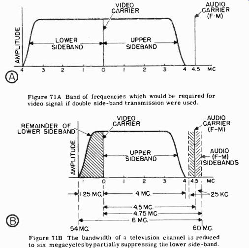
Figure 71A Band of frequencies which would be required for video signal if
double side-band transmission were used. Figure 71B The bandwidth of a television
channel is reduced to six megacycles by partially suppressing the lower side-band.
If ordinary transmission methods were used to generate the video RF signal, a band of frequencies 8 megacycles wide would be required to cover the side bands produced. Figure 71A shows a television channel when both sidebands associated with the video carrier are transmitted. This type of transmission is undesirable because of the limited amount of space in the frequency spectrum available for television use. If both sidebands were transmitted, the channel necessary for the video and sound carriers would be 9 megacycles wide. It would also be necessary Television Frequency Allocations
Channel Frequencies Channel Frequencies
2 5460 mhz 8 180-186 mhz 3 6066 mhz 9 186-192 mhz 4 6672 mhz 10 192-198 mhz 5 7682 mhz 11 198-204 mhz 6 8288 mhz 12 204-210 mhz 7 174-180mc 13 210-216 mhz
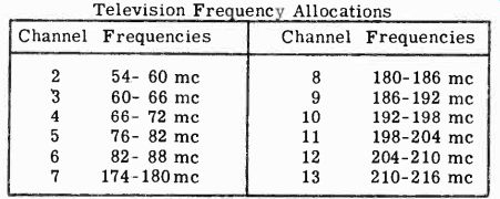
Figure 72. Frequency assignments of the twelve television channels.
to provide amplifiers in the transmitter and receiver capable of passing an extremely wide signal. Since both video sidebands contain identical information, it is possible to suppress or filter one sideband at the transmitter and still obtain all the picture information at the receiver. This type of transmission is known as a "vestigial-side band" or "single side-band" system.
Filters are difficult to construct which will cut off the undesired sideband without distorting the remaining 4 megacycle channel. This difficulty is overcome by attenuating a part of the sideband and leaving a 2 megacycle pass band on the low side of the carrier. As a result of this partial sideband suppression, the television channel can be reduced to 6 megacycles as shown in Figure 71B. The video carrier is located 1.25 megacycles from the low end of the channel, with the sideband extending for 4.45 megacycles. The audio carrier, which is frequency modulated with a maximum deviation of plus and minus 25 khz, is fixed 4.5 megacycles from the video carrier, leaving a 0.5 Mhz.
Separation between the sound and picture signals. This separation prevents cross modulation between the two signals in receivers which do not have sharply tuned resonant circuits. The separation between television channels provided by the unused remainder of the lower sideband helps prevent interaction between the video signal and the sound carrier of the next lower channel.
2-62 Television Channel Assignments. The wide 6 megacycle band required for television transmission places severe limits on the number of television stations when compared to AM or FM broadcasting. In order to accommodate a sufficient number of channels, it has been necessary to use very high frequencies.
As a compromise with the many broadcasting services demanding space in the ether, the FCC has allocated 12 channels to television between the regions of 54 and 216 Mhz. These are divided into a low and high band, channels 2-6 occurring between 54 and 88 Mhz, while channels 7-13 extend from 174 to 216 Mhz.
The frequency limits of the 12 channels is shown in Figure 72.
Originally 13 channels were allocated, but due to allocation problems, channel 1 was dropped.
In granting licenses to television stations, the FCC has arranged the channel assignments so that no two adjacent channels are used in any one area. This helps prevent interference between channels, which might occur despite the 2 megacycle guard band that exists in each 6 megacycle channel.
The FCC has made provision for further expansion of commercial television by allocating space in the region between 500 and 1,000 megacycles.
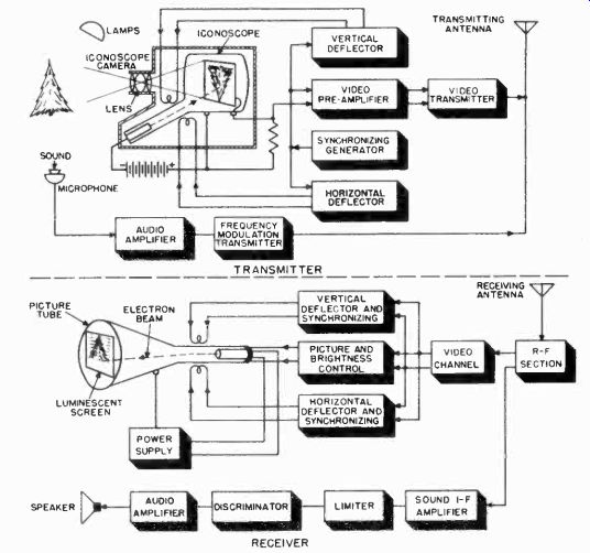
Figure 73. Block diagram of a complete electronic television system.
THE COMPLETE ELECTRONIC TELEVISION SYSTEM
2-63
Earlier in this section it was pointed out that, while the camera and picture tubes are the heart of the electronic television system, many other circuits and components are necessary. A few of these components and circuits have already been mentioned. The following is a review of what has already been discussed, and a brief description of other parts of the television system.
Figure 73 illustrates the major parts of the television station and receiver. The television system operates in the following manner:
1. The scene to be televised is focused by the lens system onto the photo-sensitive mosaic of the iconoscope tube in the camera. Each element of the mosaic stores up a charge of electricity proportional to the amount of light focused on it.
2. The camera tube electron gun shoots a stream of electrons at the mosaic, thereby discharging each tiny photocell upon which it impinges. The electron beam is made to scan the mosaic, by means of sawtooth signals supplied from the vertical and horizontal deflection circuits, starting first in the upper left corner and moving in a horizontal line to the right. The beam returns quickly to the left to begin scanning the next line of photoelectric elements. This process is continued until the entire mosaic is scanned.
3. As each element is discharged by the electron beam, an equivalent electrical signal is produced, consisting of a short pulse. The continuous series of pulses produced forms the video signal. The weak video signal is amplified by the video pre-amplifier.
4. The output from this amplifier is combined with synchronizing and blanking pulses, which are supplied by the sync generators. The sync pulses control the motion of the electron beam in the camera tube and simultaneously synchronize the electron beam in the receiving picture tube.
5. The composite video signal is fed to the modulator and radio frequency section of the transmitter, resulting in an amplitude-modulated high frequency carrier.
6. The sound signal is generated at the same time in the audio system, which consists of a standard frequency modulation transmitter, operating at a carrier frequency exactly 4.5 megacycles above the frequency of the video carrier. The audio stages include a microphone, audio amplifiers, a frequency modulated generator, and a radio frequency transmitter.
7. The outputs of the video and audio transmitters are fed to the antenna system and radiated.
8. At the receiving point, the antenna picks up the composite picture and sound signals and feeds them to the radio frequency section where they are amplified.
9. The incoming sound and picture signals are separated and fed to separate amplifier systems.
10. The separated video signal passes through several IF amplifier stages of the video section, is detected and applied to the grid of the cathode ray tube, whose fluorescent screen generates bursts of light proportional to the detected voltage on its grid.
11. The video signal is also fed to the synchronizing circuits of the receiver where the sync pulses are separated from the video information and used to control the electron beam in the picture tube. The beam thus traces out an image identical to that being scanned by the beam in the studio camera tube.
12. The sound passes through a separate IF amplifier, FM limiter, discriminator, audio amplifier, and speaker system.
The reader should now be familiar with the basic operation of the electronic television system, and well prepared to study its circuit and component details.
If the foregoing description of the fundamentals of the electronic television system has been studied carefully, the reader should have no trouble in understanding the operation and purpose of the transmitting and receiving circuits used in television.