4-52 Master Control Equipment. In describing the complex master control' room facilities, it is convenient to follow a hypothetical signal from its source to its final destination.
Nine major units and two control desks are required to handle all the master control operations.
1. A standard synchronizing generator.
2. A stand-by synchronizing generator.
3. A rack containing power supplies for the synchronizing distribution amplifiers.
4. Sync distribution amplifiers.
5. Remote facilities. This includes a bridging amplifier, sync phasing unit, and sync stretching unit which removes distortion from the sync signal.
6. On-The-Air amplifier distribution system.
7. Preview amplifier distribution system.
8. A trouble-shooting monitor which can be patched into any point in the master control system.
9. Power supplies for the video distribution system.
The block diagram of Figure 64 shows how these nine pieces of equipment are arranged in rack-form. Figure 65 shows the On-The-Air and Preview desks which are located at master control.
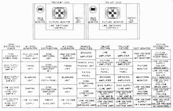
Figure 64. Master control desk and equipment layout.
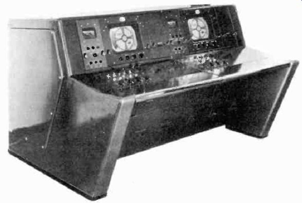
Figure 65. Preview and On-the-Air desks used in master control. (courtesy
DuMont)
The equipment listed above is sufficient to handle as many as six local studio and six remote or network programs, and provides suitable output to the transmitter, outgoing network program, on-the-air, preview, and rehearsal feeds to client rooms, executive offices, and return feeds to all studios. Each studio is arranged to have three video coaxial lines between the studio and the master control room. One coaxial line is used to provide the studio camera output to master control, and the other two coaxial lines are used to provide return feeds from master controls, to the studio of both the on-the-air program as well as that of a rehearsal or preview program.
In this way the director of a television show can view the picture which is sent to master control for broadcast purposes, as well as the return feed of this program showing the signal that is sent to the transmitter.
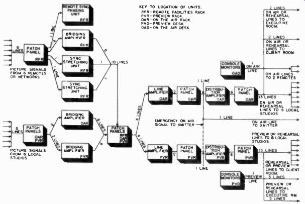
Figure 66. Block diagram of signal paths through station facilities.
The return signal maybe considerably different from the signal which originally left the studio, since the output of a film camera, or material from a remote source may have been integrated, in the master control room, with the signal that the director is sending from the studio. The second return feed from master control maybe used to show the program director the next program to be selected, should program continuity call for the outputs of two studios to be used in conjunction with one another.
Figure 66 shows a functional block diagram which illustrates the path of the picture signal through the various equipment components.
Twelve sources of program channels are available, six from local studios and six from remote or network programs. The signals from these sources appear on the patch panels associated with the on-the-air rack and the remote facilities rack. The following paragraphs will trace the signals for a hypothetical case, starting from the studios.
Of the six studios, four are ready for immediate use. Two of these go to the bridging amplifier in the on-the-air rack (OAR), and two to the bridging amplifier in the preview rack (PVR). Abridging amplifier usually provides two inputs and four multiple outputs for each input. Having passed through the bridging amplifier, there now exist four lines for each of four selected video channels. These outputs also appear on the OAR patch panel (Figure 67) and the PVR patch panel, where they are labeled OAR bridging amplifier outputs and PVR bridging amplifier outputs, the total consisting of 16 lines.
One four-channel line amplifier is situated in the OAR rack and another in the PVR. These amplifiers are controlled by push-button switches located in the on-the-air and preview desks. If remote programs are not used, four signal lines, two from each bridging amplifier, are patched through to the line amplifier in the OAR and the line amplifier in the PVR. The output of the on-the-air line amplifier consists of two lines, each carrying the same signal. This signal can be any one of the four at the input.
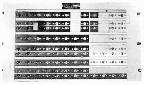
Figure 67. On-the-Air patch panel. (courtesy DuMont)
The two outputs again appear on the OAR patch panel. One is permanently tied to the transmitter input, the other is connected to a studio distribution amplifier. The studio distribution amplifier is identical to the bridging amplifier except that its inputs and outputs are multiplied in a different manner. It is arranged to have but one input line and six output lines. Each of these six output lines appears on the OAR patch panel and together they represent the on-the-air program. One output is returned to the on-the-air desk, where it appears on the console monitor, and another is returned to the selected studio to indicate what material is on the air. The remaining four lines are set up on the OAR patch panel to feed the signal to client rooms, network outlets, or executive offices, as required.
Returning to the preview line amplifier, its two outputs are fed to the PVR patch panel where one is reserved as a standby for transmitter feed, and the other is sent to the PVR distribution amplifier. The six output lines, from the distribution amplifier appearing on the PVR patch panel, are divided in a similar manner as those on the OAR patch panel. One is fed to the preview desk to be displayed on the console monitor, and another is returned to the studio as a preview return feed. The four remaining lines can be distributed as required.
The above analysis has been predicated on the absence of remote or network programs. Since these constitute a major source of programming material, most stations make extensive use of them.
4-53 Network Programs. Tracing the signals through the block diagram of Figure 66, it will be found that six remote sources appear on the Remote Facilities Rack (RFR) patch panel. If the video signal is stable enough and does not require modification, it may be patched directly to one of the four remote bridging amplifier inputs, appearing as eight output lines on the RFR patch panel. Alternatively, two of the remote program sources may require sync modification, in which case they are fed through sync stretchers on the RFR patch panel.
In the sync stretcher units, the correct sync-to-picture ratio is restored. The outputs appear on the RFR patch panel. By means of the latter facility, it is possible for two sync stretchers to service a number of successive remote programs. A maximum of ten signal lines appear as outputs on the RFR patch panel. These are selected as required for the line amplifiers in both the OAR and PVR, and are directed to the transmitter network outputs or to other points.
By way of summary, these operations may be grouped as follows: Of a total of six local studio signals and six remote network programs, four may be selected for immediate use.
They are selected by push-buttons in the line amplifier and the output fed to the transmitter and other points that require the on-the-air signal.
The four selected channels are normally fed to the line amplifier in the PVR and dispatched from this point as preview return feeds to whatever locations require the signal. It is of course possible to re-route other program channels for subsequent operations while one channel is being continually fed to the transmitter. Numerous combinations of facilities can be made by patching. For example, the output of the preview line amplifier may be used to feed a program to the network different from the program fed to the local transmitter. For such portions of the network program as might be carried by the local transmitter, an arrangement could be made through the use of switching circuits in the on-the-air line amplifier.
4-54 Synchronizing Problems. When switching from studio to remote pick-up, two synchronizing generators are involved; one associated with the remote program and the other with the local studio. While it has not been found necessary to lock the synchronizing generators together at the horizontal sweep frequency when remote and local programs follow each other, it is important that they be locked together at the vertical sweep frequency rate so as to prevent loss of vertical synchronization at the receivers in the field.
This synchronization may be secured in either of two ways.
If the remote program emanates from a location within the same power line district as that of a master control installation, and if both synchronizing generators are locked with the 60 cycle line, they may differ in phase but they will be of the same frequency. If the remote operations crew can receive an off-the air signal from the main transmitter, it can adjust the phase of the remote synchronizing generator with respect to that in master control. Alternatively, the master control sync generator may be phased to meet the requirements of the remote sync generator.
4-55 Sync Phasing. When the remote program is derived from a location in another power line district, the synchronizing generators may differ in both phase and frequency of the vertical synchronizing signal. In this case, if vertical synchronizing continuity is to be maintained, it is essential that the synchronizing generator in the master control installation be locked to the sync generator frequency of the remote or network program.
To accomplish this, a sync phasing unit is incorporated in the master control remote facilities rack. Its input appears on the RFR patch panel. The output of the sync phasing unit is fed as a 60 cycle signal to the master control sync generator, and serves to lock it with respect to the remote or network program in both phase and frequency.
A block diagram of a circuit used for phasing remote and master control sync generators which are on different power lines is shown in Figure 68.
The remote video signal is fed into V-1 and amplified. The next stage clips the video portion and leaves the sync signals.
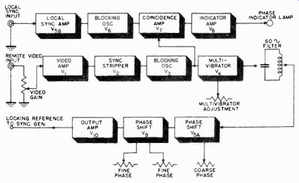
Figure 68. Block diagram of sync phasing unit.
The vertical sync is separated and triggers V-3, which is a blocking oscillator. The output pulse of the blocking oscillator triggers V-4, a multivibrator, whose output circuit includes a 60 cycle resonant filter. V-4 thus generates a sine wave at the vertical frequency of the remote sync with a fixed phase relationship to the vertical sync interval. This sine wave is applied to a phase shifter, V-5a, whose output is applied to two more phase shifting stages in V-9. The output of the phase shifter is applied to V-10 whose plate circuit includes an output transformer which supplies a 60 cycle locking signal to the master control sync generator.
Returning now to the local sync input, negative sync pulses from the master control sync generator are amplified by V-5b.
After the vertical sync signal is separated, it is used to trigger another blocking oscillator, V-6. Thus a pulse is obtained, occurring at the vertical interval of the master control sync generator, and of the same shape and relative timing as that generated by V-3. The pulses from V-6 and V-3 are fed to a coincidence amplifier, V-7. In such an amplifier, the grids are biased so that the tube will conduct only if the two input signals coincide within certain time limits. If so, the addition of the two voltages is sufficient to overcome the cutoff bias. If the two signals do not coincide, neither is able to make the tube conduct.
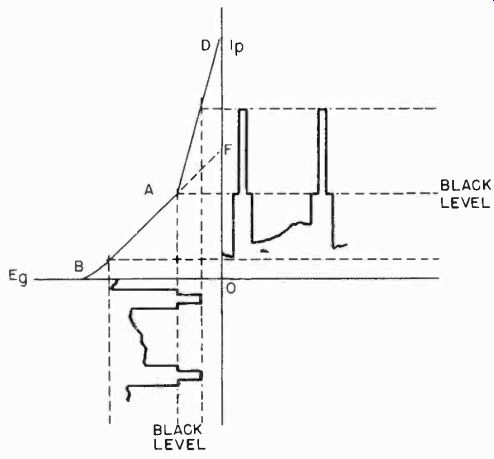
Figure 69. Grid-voltage, plate-current curves of non-linear amplifier stage.
The phasing controls in the phase shift circuit are adjusted until the two signals coincide. This is indicated by a lamp which lights up when the coincidence amplifier conducts and sends a signal to V-8. V-8 amplifies the indicating signal, causing the lamp to light. Under this condition a correctly phased signal is obtained from V10 for locking the master control sync generator.
4-56 Stabilizing Amplifiers. If the signal from the remote source contains spurious signals, such as hum, thermal noises, and other random disturbances, it must first be stabilized at master control before being fed to the transmitter. This is done in a sync stretcher or stabilizing amplifier. In such a unit, the signal is first amplified by several video amplifier stages.
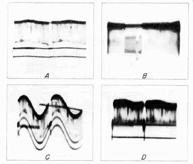
Figure 70. Effect of sync stretching unit on video signal.
The signal is then fed to three non-linear amplifiers so that the sync pulses are amplified by a larger factor than the other parts of the signal. Figure 69 shows how the three non-linear amplifier stages function. One of the three tubes operates as a normal amplifier, and contributes signal through that part of the characteristic curve between B and F. At grid voltages above the black level (point A), the remaining two tubes begin to amplify the signal, giving the increased slope between A and D. This stage, therefore, automatically stretches the sync pulses, thereby increasing the sync-to-picture ratio without adversely affecting the picture signal.
The black level, or peaks of blanking are held at A by a clamping or d-c restoration circuit which functions independently of the picture signal in the amplifier. It holds the peak of each blanking pulse to the correct point on the amplifier curve.
Clamping action is independent of the signal, so that spurious additive components are eliminated from this sync-amplifying stage. Amplified sync thus passes on to the clipping stage which clips off part of the sync to restore the correct sync-to-picture ratio.
The oscillograms shown in Figure 70 indicate how effectively a stabilizing amplifier corrects extremely defective video signals. Figure 70a shows an essentially noise-free signal. The signal is not perfect since it contains a small amount of hum which can be observed as a wavy bottom line (sync peaks). To this signal two types of spurious signals were deliberately added separately, a high frequency hiss and 60 cycle hum. The signal after the addition of the hiss is shown in Figure 70b. As can be seen, the amplitude of the hiss is about 50% of the total signal amplitude, and almost obliterates the horizontal sync pulses.
Figure 70c shows the signal after the addition of 60 cycle hum equal to about 75% of the total signal. Both these signals were then combined and fed to a stabilizing amplifier. The resultant signal is shown in Figure 70d. It will be noted that the hum has been completely eliminated, and an increase in the sync-to-picture ratio has been effected. In addition, there is a considerable improvement in the signal-to-noise ratio.
REMOTE CAMERA CHAIN
4-57
The remote camera equipment used for field pick-up is essentially the same as the studio equipment. The remote equipment is capable of televising a program and generating the standard video signal. It operates completely independent of the station, except when it is desirable to lock the frequency of the remote sync generator to the frequency of the station sync generator. Other than the fact that the remote facilities are designed for portable use, they incorporate the same basic components as studio facilities. A typical remote camera chain is shown in the block diagram of Figure 71.
The following paragraphs describe a dual camera chain, rather than a single camera chain as was described in the very simple television system. Remote chains usually employ from two to four cameras.
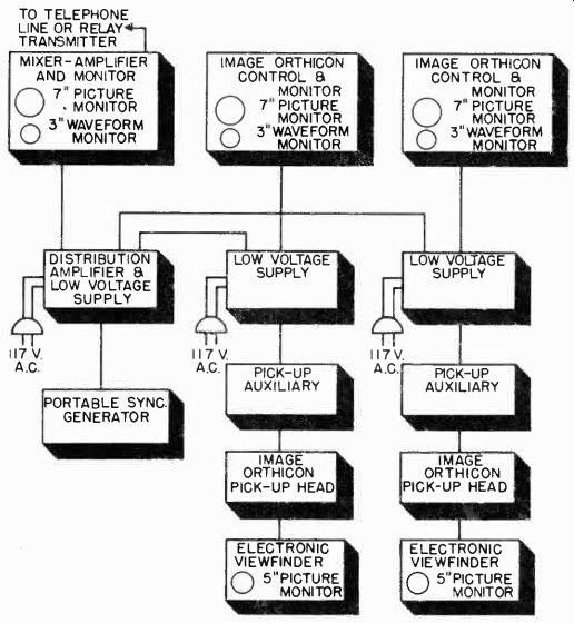
Figure 71. Block diagram of dual image-orthicon camera chain.
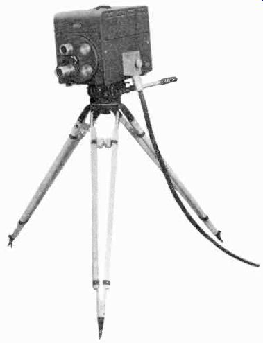
Figure 72. Pickup head mounted on tripod for remote pickup use. (courtesy
Raytheon)
Figure 71 shows the thirteen units of equipment used in a dual camera chain. The pick-up head and the Electronic Viewfinder are embodied in the camera so that actually only eleven individual pieces of equipment make up the remote facilities.
4-58 Equipment Design. The circuits of the units in the remote camera chain are the same as described for studio equipment. The distinguishing feature of remote equipment is its mechanical design. Remote equipment is portable and compact.
The following comparisons with studio equipment indicate the major differences between studio and remote equipment.
4-59 The Pick-Up Head. The pick-up head uses an image orthicon tube similar to that used in the studio. The major difference between the image orthicon tubes used for remote and studio use is their color response. Blue sensitive image-orthicon tubes are best for televising outdoor scenes, while red sensitive tubes perform better under artificial lighting in studios. For field work the pick-up head is mounted on a tripod rather than a dolly (Figure 72).
4-60 The Electronic Viewfinder. The electronic viewfinder is the camera operator's picture monitor. It is located on top of the pick-up head and is identically the same as the unit used in the studio camera.
4-61 The Pick-Up Auxiliary. The pick-up auxiliary is usually mounted in a box located close to the camera (Figure 73). It contains the voltage regulator circuits for the camera circuits which separate the vertical and horizontal sweep driving pulses coming from the sync generator. By locating these circuits in the pick-up auxiliary, the camera head is made smaller and lighter. In studio equipment, the auxiliary circuits are usually located in the dolly or in the camera head.
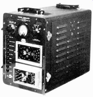
Figure 73. Pickup amplifier. (courtesy DuMont).
4-62 Low Voltage Supply. This unit supplies filament voltage and unregulated d-c voltages to the camera, pick-up auxiliary, and the camera control monitor. It is mounted in a box, (Figure 74), whereas in the studio the low voltage supplies are rack mounted.
4-63 Camera Control Monitor. The camera control monitor in remote equipment assumes the functions performed by both the picture monitor and the mixing amplifier in the studio. Each camera has a separate control monitor containing a picture monitor and an oscillograph monitor (Figure 75). In field equipment the picture tube is 7" in diameter, and the oscillograph monitor tube is 3" in diameter. The video signal from the camera is combined with the sync and blanking signals from the portable sync generator in the mixing amplifier section of the camera control monitor. If only one camera is used in the remote system, the composite video signal from the control monitor is fed directly to the relay transmitter or telephone line.
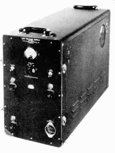
Figure 74. Low-voltage supply. (courtesy DuMont).
When more than one camera is used, an additional mixing amplifier and monitor is necessary.
4-64
The Mixer-Amplifier and Monitor. In both studio and remote equipment, a mixer-amplifier and monitor must be added to the system, when more than one camera is used, to combine the camera outputs and switch any one of them on the air. A picture monitor and oscillograph monitor are incorporated into the unit so that the video operator may observe the particular camera signal which he has selected (Figure 76). A system of "on-the-air" lights, located on the monitor panel, indicates which channel is in use. By means of push-buttons, the operator may instantaneously switch from one camera to another. A "fade rate control" is also generally provided so that when the cameras are switched, one picture fades out and the other fades in. The fade rate can be controlled in steps for slow, medium, fast, and instantaneous changes.
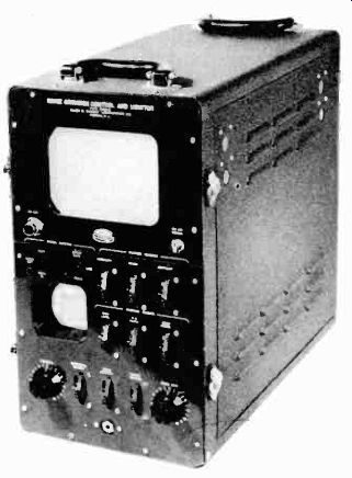
Figure 75. Camera control monitor. (courtesy DuMont)
4-65
The Mixer-Amplifier Circuits. A block diagram of this section is shown in Figure 77. Each of the video channels consists of a cathode follower coupled to a video amplifier which has a voltage gain sufficient to overcome the attenuation of the cathode follower. Gain controls are located at the input of each stage for equalizing the signal level from each camera.
Switching between channels is accomplished by variation of the grid bias on the amplifier stages, and the rate of fade is controlled by the variation of time constants of bias networks, located in the cathode-follower inputs.
If a signal from channel 1 is being delivered to the transmitter, and it is desired to fade out this picture slowly, and at the same time bring in a picture from channel 2, the grid bias on the video amplifiers in the two channels should vary as shown in Figure 78 to accomplish this. This represents the ideal case, for the rate at which the amplifier in channel 2 reaches full conduction is the same as the rate at which the amplifier in channel 1 is being cut off. The cross-over point of the two curves is at the cutoff voltage of the amplifiers and one picture disappears just as the other one appears.
The arrangement of Figure 79 is a means of approximating the conditions of Figure 78. Initially, switch SW-1A is closed, the amplifier grid for channel 1 is at ground potential, and signals from this channel pass to the output. Switch SW-1B is open, leaving the amplifier grid of channel 2 at a potential well beyond cutoff. If SW-1A is opened and, simultaneously, SW-1B is closed, the voltage on the grid of amplifier 1 will fall to the potential at point B at rate determined by the double time constant R1-C1 and R2-C2. At the same time the potential on the grid of amplifier 2 will rise to ground potential at a rate determined by the single time constant R3-C3.
Figure 76. Mixer amplifier and monitor. (courtesy DuMont)
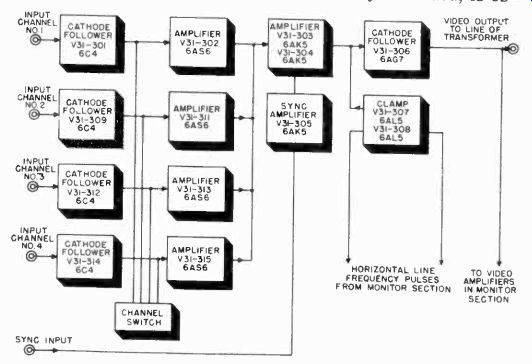
Figure 77. Block diagram of mixer amplifier.
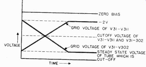
Figure 78. Curve of bias changes which occur in switching amplifiers.
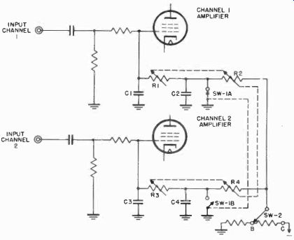
Figure 79. Simplified schematic of input switching circuits.
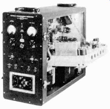
Figure 80. Portable sync generator. (courtesy DuMont)
If the potentiometers R-1, R-2, R-3, and R-4 are ganged, it will be possible to vary the slope of the two curves and therefore the rate of fade. The cross-over point, which determines whether or not the signals are mixed as they are faded, is established by the position of switch SW-2, which sets the cutoff voltage. In actual practice, more than two channels are employed, and it is possible to select any channel or combination or channels by depressing the correct push-buttons. A selector-switch (rather than ganged potentiometers) controls fade rate with positions indicated as "Slow", "Medium", "Fast", and "Instantaneous".
4-66 Distribution Amplifier and Low Voltage Supply. This unit contains the low voltage supplies for the Mixer-Amplifier and Monitor, and also several cathode follower stages which distribute sync and blanking signals from the sync generator to the cameras in operation. In the studio, the distribution amplifiers and power supplies are located on separate chassis mounted in racks.
4-67 The Sync Generator. This unit (Figure 80) is similar to the studio sync generator. It supplies standard RMA blanking and sync pulses for all units of the camera chain. At the station, the studio sync generator is locked to the remote sync generator so that the two operate in phase. This permits switching from studio programs to remote programs without loss of synchronization of receivers in the field.
MICROWAVE RELAYS
4-68 Since remote pickup equipment is used in widely different locations on short notice, it is desirable to provide a number of relay methods whereby the remote pickup signals can be fed back to the main transmitter location. When a regular schedule of pick-ups is planned, as for example, from a sporting arena, it is possible to install coaxial cable facilities to the transmitter.
Carefully chosen telephone lines with suitable line amplifier terminal equipment can also be used. Using such facilities, the television signal may be fed by line from the remote pick-up equipment line amplifier to the master control room at the transmitter.
For special pick-ups, it is often desirable to use a wireless relay link. Relay transmitters are of relatively low power since the transmission takes place between two specific points, permitting the use of highly directional transmitting and receiving antennas. Power outputs of 500 watts permit transmission over distances up to 15 miles, with equipment operating in the vicinity of 7000 Mhz. At the transmitter, a high-frequency receiver is used to pick up and detect the video signal and feed it to the master control room.
Radio relays are also being set up between cities to provide links between television stations. Because the range of television signals is limited to about 50 miles, a great many of these relay stations are necessary to provide television network facilities, comparable to those used for radio broadcasting. Television networks are being made up by linking stations with radio relays or a combination of radio relays and coaxial lines. Another method of transmitting television signals over long distances is "stratovision". In the stratovision system a television transmitter in a plane beams the signal down on the earth, covering a very large area. Stratovision is still in its experimental stages and has not yet been used for commercial operation.
4-69 Television Relay Transmitters. Television relay transmitters are complete portable transmitting systems consisting of a transmitter and a highly directional antenna which may be rotated on a mounting unit. The transmitter may operate on one of several television relay bands assigned by the F.C.C. The bands presently assigned for relay work are in the 2,000, 4,000, and 7,000 megacycle regions. The parabolic antennas used at these frequencies provide a high gain and limit the output signal to a line of sight path.
4-70 Transmitter Circuits. Other than the fact that the relay transmitter operates at a much higher frequency than the station video transmitter previously described, its basic sections are the same. The principal difference in the relay transmitter design is in the method of generating the ultra-high frequency RF carrier. Conventional vacuum tubes are incapable of oscillating at these high frequencies. Tubes such as the klystron and magnetron which were developed during the last war for use in radar equipment are used in the relay transmitter oscillator. At these frequencies, capacitors, inductors, and even coaxial lines are not suitable for the tuned circuit elements of the oscillator. Instead, cavity resonators are employed.
A discussion of ultra-high frequency oscillators and cavity resonators is beyond the scope of this guide. There are many excellent references on this subject which the reader will find in the bibliography if he wishes to pursue this subject further.
Suffice to say here that the relay transmitter consists of an ultra high frequency RF generator, a video modulator, and a highly directional antenna which confines the radiated television signal to a very narrow beam.

Figure 81. Microwave relay link between New York and Boston.
4-71 Relay Receivers. At the relay receiver, a second directional antenna receives the narrow television beam. A klystron or magnetron ultra-high frequency oscillator is again employed to heterodyne the incoming signal. This produces a video IF frequency. From this point on the relay receiver is identical to conventional superheterodyne receivers. The IF signal is amplified and detected. The detected signal is the 4 megacycle video signal which was used to modulate the transmitter. In the relay receiver, the detected signal is amplified by one or more video amplifier stages to bring it up to approximately 1 volt, at which level it is fed by co-axial line to the master control room.
After being monitored at master control, the relayed signal is fed to the station's transmitter.
4-72 Television Networks. Two methods are being used to distribute television programs, namely co-axial cables and radio relay stations. Coaxial cables are now being installed which will link the major cities from coast to coast some time between 1950 and 1953. The cost of laying coaxial cable is several dollars per foot, bringing the cost of co-axial links to many millions of dollars when they are extended across the country.
As a result rental fees for using these lines are high. Many stations are therefore building or renting radio relay links which they believe will eventually prove cheaper to operate.
A radio relay link now exists between New York and Boston, a distance of 220 miles. Relay stations are located at the points shown on the map of Figure 81. This system is equipped with four different relay frequencies in the 3,700 to 4,200 Mhz band.
The carrier frequencies are at least 40 Mhz apart to avoid crosstalk between incoming and outgoing signals. The antennas used at the relay points are designed for operation at two frequencies, the regular channel and a standby channel.
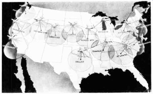
Figure 82. How coverage of United States would be secured using stratovision.
(courtesy Westinghouse)
All of the seven relay stations of Figure 81 are identical, each having a receiver and a repeater transmitter.
4-73 Stratovision. This transmitting system is being developed by Westinghouse. The television transmitter is placed in an airplane and the television program broadcast from the airplane while it is in flight. The transmitter's coverage area is increased by virtue of the increased line-of-sight distance to the horizon. At an altitude of 20,000 feet, a coverage radius of 50 miles is possible, which is about the distance reached by the average transmitter on the ground. At an altitude of 30,000 feet, a coverage radius of 210 miles is possible, and at 50,000 feet, about 300 miles is possible.
Approximately 20 kilowatts of power are needed at a ground station to transmit a usable signal a distance of approximately 50 miles, whereas only one kilowatt of power will deliver the same usable signal 200 miles from a transmitter located in a plane flying at 30,000 feet.
A stratovision network of 8 planes could link New York and California, as compared to the 100 ground relays necessary to fulfill the same purpose. Fourteen planes carrying transmitters could supply television programs to 78% of the population of the United States as shown in Figure 82.
The designers of stratovision envision a system operated in the following manner. Airplanes would take off at staggered Figure 83 An airplane equipped to broadcast television programs. (courtesy Westinghouse) four hour intervals, remaining at 30,000 feet for eight hours each. This will keep a plane in the air at all times. A standby plane would always accompany the one in use and be ready to take over in case of airplane or transmitter trouble. At each stratovision area, four planes would be required so that while two were flying the other two would be undergoing maintenance or repairs. A completely equipped plane with transmitting and receiving antennas is shown in Figure 83.
The transmitting plane would fly in circles at about 30,000 feet.
The program originating in the studio would be transmitted to the plane by a small ground transmitter and directional antenna system. To make the system economical to operate, large planes, capable of carrying two or more transmitters, thereby splitting the operating costs among several stations, could be used.
Stratovision is one of many systems conceived by engineers to extend the boundaries of line of sight transmission. Many schemes, which today seem fantastic, may some day be made entirely practical. A typical suggestion is that of putting an artificial satellite or moon out in space, made of metal and shaped like a spherical mirror. Television signals beamed at this mirror would be reflected over a very large portion of the earth.
Proponents of this idea point out that once this satellite is shot from the earth's atmosphere (say, by an atomic rocket), it would circle indefinitely in the free space surrounding the earth.
COMMERCIAL STATION EQUIPMENT
4-74 The average size television station consists of studio facilities for picking up live talent programs, film cameras, one or more remote camera chains, and a video and audio transmitter. In very small stations, portable camera chains can be used for both studio and remote work to keep equipment to a minimum. A floor plan, showing a typical grouping of the above equipment in a small station, is shown in Figure 84.
The station shown has one live talent studio with a control room for local monitoring of the cameras. The film room has one film projector which is focused on an iconoscope camera.
The iconoscope picture is monitored at the master control console which has switching facilities for integrating programs from the film pick-up and the studio. At this master control console, programs may be fed in from a network. The transmitter racks are mounted in the same room. This eliminates the need for a separate picture monitor for the transmitter. An announcer's booth, a client's room for viewing programs, and a garage for housing the mobile unit complete the station's facilities.
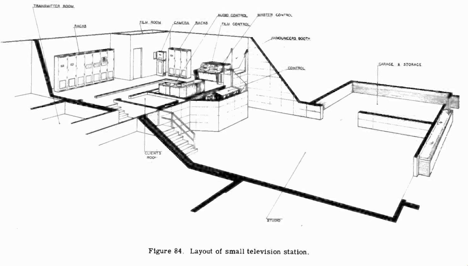
Fig. 84
This small station is typical of many that will appear in small communities about the country. Larger stations located in the big cities are basically the same, but contain several studios, and the added equipment necessary for these studios.
4-75 Studio Equipment. At present, manufacturers are making only image orthicon cameras for live talent studio pick-ups. A few of the older stations still use iconoscope cameras made before the war. The studio camera equipment consists of the camera itself, a camera control monitor, mixing and distribution amplifiers, and a synchronizing generator. Usually, only the cameras and control monitors are located in the studio control booth. The sync generator and the distribution amplifiers are located in master control so that signals can be fed to several studios.
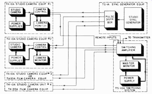
Figure 85. Block diagram of RCA studio camera equipment.
4-76 RCA Studio Camera Chain. The arrangement of studio equipment provided by RCA is shown in Figure 85. A brief description of each unit follows.
The camera can be put on a dolly as shown in Figure 86, or on a boom structure as shown in Figure 87. The boom structure makes it possible to take interesting overhead shots.
The camera consists of image orthicon deflection circuits, a preamplifier, and an electronic viewfinder, all mounted in one unit. Camera circuits are arranged to either side of the image orthicon tube (Figure 88). Hinged doors on either side of the camera swing down to provide easy access to the camera circuits.
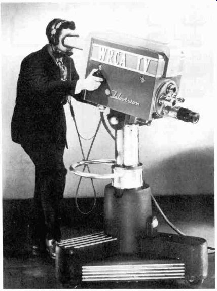
Figure 86. RCA Camera on dolly. (courtesy RCA)
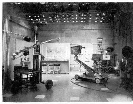
Figure 87. Studio set and boom camera. (courtesy WFIL-TV)
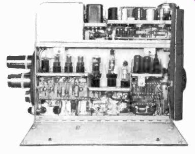
Figure 88 Interior of image-orthicon camera. (courtesy RCA)
Four lenses are mounted on a lens turret, which can be rotated by a handle at the rear of the camera. These lenses are relatively small, due to the small size of the photo-cathode in the pickup tube. They are available in sizes from 35 mm f2.8 to 135 mm f3.8. Optical focusing is accomplished by adjustment of a knob on the side of the camera. This knob moves the pickup tube, and its focus and deflection coil assembly with respect to the lens.
Controls for the studio camera circuits are located at the rear of the camera in two rows behind hinged covers, as shown in Figure 89. These controls are normally preset and do not require adjustment during the program.
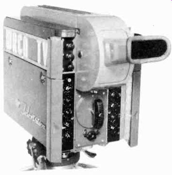
Figure 89. Rear of RCA camera with doors open to show controls. (courtesy
RCA) 4-77 Studio Picture Monitor. The studio picture monitor enables the video
operator to monitor and control the quality of the picture signal produced
by the studio camera. It is a desk type console section with a 10-inch picture
tube monitor mounted in the upper section (Figure 90). A 5-inch oscillograph
tube, which reproduces the video signal waveform, is located below the picture
tube. Controls for setting the camera signal gain, and black level, are brought
out on the monitor front panel.
The control chassis below the monitor contains the necessary circuits for amplifying the video signal, establishing the black level, adding picture blanking to the picture signal, adding the synchronizing signal, and providing 3 separate outputs. Four commonly used controls are located on the monitor. These are:
1. orthicon focus
2. beam current
3. target voltage
4. image focus
4-78 Studio Camera Switching System. Picture monitors can be installed together in the studio control room to handle several cameras. The RCA desk type sections are fastened together to form an operating console which provides a control center for camera switching, monitoring and other technical aspects of programming. In stations where live talent programming is not planned, but where facilities are employed for film projection, broadcast of network programs and relay pickups, the switching console can be located in the transmitter room or in the projection control room together with the film equipment. If both film and live studio pickups are to be integrated, the studio console can also contain a film monitor.
The studio camera switching equipment enables a single video operator to do the following: (1) Select any signal from six input lines; (2) switch or fade the desired signal into the program line; (3) fade out the previously selected signal and fade in another, simultaneously and at any speed; (4) switch instantly from one signal to another; and (5) superimpose two signals with any desired degree of brightness for each signal. Figure 91 shows a close-up view of the switching console monitor.
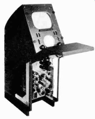
Figure 90. Studio picture monitor. (courtesy RCA)
Electrically, the studio camera switching console includes all the circuits necessary to accomplish four operations, namely:
1. Video switching a six pushbutton selector provides for selecting any one of six input signals for transmission to a master control room or to the transmitter.
2. Sync addition Amplifier circuits combine sync from the Figure 91. Camera switching monitor controls. (courtesy RCA) studio sync generator with the camera video signals to form the composite video signal.
3. Monitor switching A three position switch provides for selection of either of two remote (network or relay pickup) signals for preview, or the signal being sent to the transmitter or master control room.
4. A communication system permits the technical director and program director to converse with all engineering and production personnel.
4-79 Synchronizing Generator. The studio synchronizing generator is an integral unit complete with power supply. It is assembled in a standard cabinet-type rack, as shown in Figure 92.
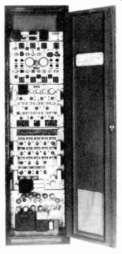
Figure 92. Studio type synchronizing generator. (courtesy DuMont)
The sync generator is generally located in the master control room. Its signals are fed to several studios through distribution amplifiers.
Some studio synchronizing generators have self-contained oscillograph monitors for checking the frequency of the divider circuit. Figure 93 shows the presentation on the screen of the cathode ray tubes. This type of pattern is obtained on the Du Mont studio synchronizing generator which has a master oscillator frequency of 157.5 khz. This is five times higher than the 31.5 khz. master oscillator frequency used in most sync generators. The higher frequency is used in the DuMont design to provide 157.5 khz. pulses for checking the horizontal linearity of sweep circuits.
The left hand screen is that of the high frequency monitor whose time base is 900 cycles. The dots represent the master oscillator frequency of 157.5 khz. There are five dots along each line or step in the vertical "ladder", indicating division from 157.5 khz. to 31.5 khz. The bright dots on the high frequency monitor correspond to the 15.75 cycle horizontal repetition rate.
There are seven steps in each of the "ladders", indicating a frequency division from 51.5 khz. to 4,500 cycles. In other words each "ladder" represents 4,500 cycles. The presence of five "ladders" for each cycle of the time base points to a frequency division from 4,500 cycles to the time base frequency of 900 cycles.
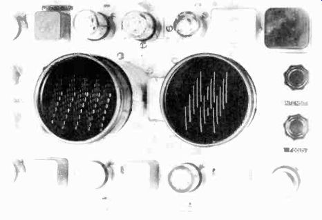
Figure 93. Screens of cathode-ray tube indicators for monitoring synchronizing
generator. (courtesy DuMont)
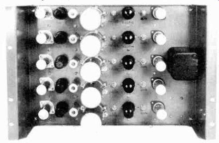
Figure 94. Distribution Amplifier. (courtesy RCA).
At the right on the low frequency monitor, the "ladder" steps represent 900 cycles. Since there are five of them to each "ladder", the indication is frequency division from 900 cycles to 180 cycles. The three "ladders" per cycle of the time base indicate a frequency division from 180 cycles to 60 cycles. The blanked-out section in the middle of the low frequency scan is derived from the 60 cycle power line and confirms the time base of 60 cycles. It also indicates synchronism with the line. When the generator is not locked to the 60 cycle power line, the blanked-out section moves across the time base. This presentation has been found highly useful in the analysis at a glance of synchronizing generator failures due to improper timing.
4-80 Distribution Amplifier. The distribution amplifier shown in Figure 94 may be used in any one of the three following applications: (a) to feed video or synchronizing signals from a single source, such as a sync generator, to several outlets; (b) to mix video signals from several sources in order that they may be fed to a single output line; and (c) as a straightforward line amplifier to bring the video signal up to required levels between different points in the television system.
4-81 Film Pickup Equipment. Specially built iconoscope cameras are used almost exclusively for film pickups in a television station. The iconoscope gives a higher quality picture than the image orthicon and is used for film work because all the light from the film is concentrated on the iconoscope mosaic and is thus sufficient to obtain pictures of good contrast. The iconoscope camera used for a film pick-up is stripped of superfluous accessories such as lenses, optical focus controls, and viewfinder. In a typical arrangement, shown in Figure 95, the motion picture projector is permanently mounted opposite the iconoscope camera. The picture is focused directly on the iconoscope mosaic.
Because standard motion picture films must be projected at a rate of 24 frames per second and television images are shown at a rate of 30 frames per second, a system of scanning had to be developed to compensate for the difference in frame frequencies.
The projector mechanism is so designed that three fields of the television picture are secured during the time that one film frame is held before the open shutter. The film is then pulled to the next frame, and two more field scans of the picture are secured. In this way, two frames of film occur for five field scans of the television picture. Therefore, two film frames running through the projector at the standard rate of 24 frames per second will consume 2 x 1/24 seconds or 1/12 seconds.
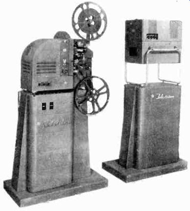
Figure 95. Typical arrangement of film camera and 16mm film projector. (courtesy
RCA)
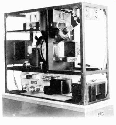
Figure 96. Iconoscope film pickup camera without shield covers. (courtesy
DuMont).
These two film frames have been utilized in the interval in which 5/60 of a second (or 1/12 of a second) has been consumed for five flashes (or fields) of picture. Synchronization is thus maintained between the 60 fields per second of television scanning, and the 24 frames per second of film motion.
The projector must be driven by a synchronous motor so that it is locked to the power line frequency. The motor is phased with respect to the frequency of the synchronizing generator which drives the entire television system. Since both the synchronous motor and sync generator are locked to the same 60 cycle line, synchronization is maintained once the two units are phased with respect to each other.
4-82 Film Pickup System. The DuMont iconoscope film pickup system is typical of film systems utilizing a 16mm projector, an iconoscope camera, and a monitoring console.
An interior view of the iconoscope camera is shown in Figure 96. This unit contains the pickup tube, the sweep circuits, a five stage video preamplifier, regulator circuits for the video amplifier voltages, a blanking amplifier for cutting off the beam during return trace periods, and a protection circuit which removes the accelerating voltage from the pickup tube in the event of sweep failure.
The video signal is fed to a monitoring console, Figure 97.
This monitor contains both a picture and an oscillograph monitor. The operating controls include iconoscope sweep amplitude, sweep position, focus, and intensity. The shading of the picture is also accomplished at this console.
The picture obtained with an iconoscope camera must be shaded to correct for the spurious effects of secondary emission that occur in this type of pickup tube. The high velocity beam striking the elements of the mosaic causes secondary electrons to be emitted. Those elements near the center of the mosaic sometimes release their secondary electrons to nearby elements, as well as to the wall coatings of the tube. Elements near the edges of the mosaic release their secondary electrons largely to the conducting areas around the mosaic. Thus central elements may deliver different amounts of secondaries than do edge elements, even when there is no light falling on the mosaic.
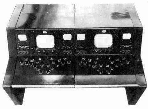
Figure 97. Iconoscope film camera monitor showing shading controls. (courtesy
DuMont).
This difference appears as a video signal, and as such causes the receiving tube to show a variation in illumination over the scanned area.
When a scene is focused on the mosaic, the video signal which it produces is distorted by this spurious signal distribution. For example, a picture which would otherwise have uniform illumination would appear bright in the center and gradually become darker toward the edges.
In the early stages of the video pre-amplifier, a sine wave voltage of proper amplitude and phase can be introduced which distorts the video signal in a manner which compensates for the uneven illumination. The sine wave is one form of shading signal. In practice, the video operator has a choice of three types of shading signal voltages which he can inject into the pre-amplifier stages to produce even illumination. These are the sine wave, saw-tooth, and parabola shaped voltages of Figure 98.
There are two controls for each waveshape, making six in all.
One of the two controls operates a shading signal at the line frequency, the other at the frame frequency. With a little practice, the video operator can learn to use any combination of shading signals to provide uniform illumination of the picture. He must constantly manipulate these controls, for the spurious secondary emission will change with changes in picture content.
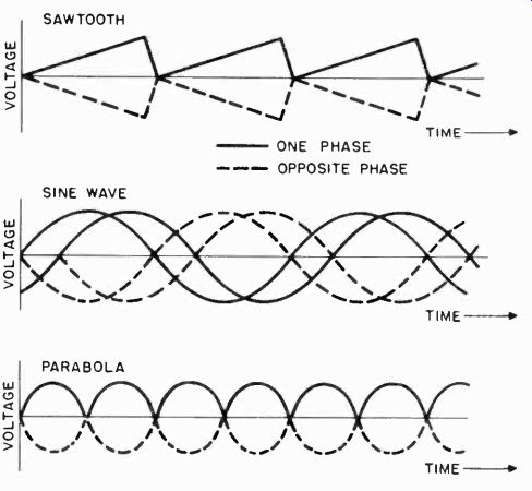
Figure 98. Waveshape used to shade picture.
Some studios use more than one film camera, in which case console units are combined as was done in making up a console desk for several studio floor cameras.
RCA offers a film "multiplexer" unit which eliminates the need for a separate iconoscope camera for each projector. The film multiplexer is an image reflecting device fitted with a standard slide projector. Images can be picked up from the slide projector or from either film projector without moving the film camera or any of the projection units; therefore, all three units can be fastened permanently to the projection room floor at the time of installation.
The film multiplexer mirrors reflect the image from either of the two film cameras onto the pickup tube in the iconoscope camera. The equipment is mounted as shown in Figure 99.
The slide projector, which is focused directly on the pickup tube in the camera provides a means for picking up the station test pattern or for projecting still shots during the program.
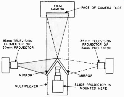
Figure 99. Physical layout of film multiplexer.
4-83 Monoscope Camera. The monoscope camera is used for obtaining a test pattern image for testing of the television system. If the monoscope pattern is put on the air during stand-by periods, the station call letters maybe made part of the pattern, if the tube is custom made. A block diagram of a monoscope camera is shown in Figure 100. The circuit is much the same as a picture monitor. It contains a video amplifier to strengthen the monoscope signal, and vertical and horizontal deflection circuits which control the scanning beam in the monoscope tube.
These circuits are synchronized by driving pulses from the sync generator. A blanking amplifier is used to control the level and polarity of the blanking pulses received from the synchronizing generator before the pulses are fed into the video amplifier and mixed with the video signal. The output signal obtained from the monoscope contains only blanking and video signals, as shown in the figure. Sync signals are added in a mixing and distribution amplifier in the master control room.
4-84 Flying Spot Scanners. Another type of camera, known as a "flying spot scanner", is useful for presenting test patterns, program titles, and films. A common method of televising test patterns or program announcements is to set up a card in front of a studio camera or use a slide with a film camera. This ties up operating personnel and a camera. The monoscope camera is not flexible enough to perform this function because it has a fixed pattern. The flying spot scanner offers a solution to this problem because it is a relatively inexpensive type of camera.
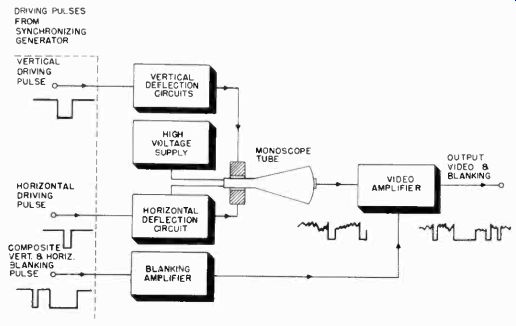
Figure 100. Block diagram of monoscope camera circuit.
The principle of the flying spot scanner may be explained by referring to the block diagram shown in Figure 101. A scanning raster is formed on an electrostatic or magnetic cathode ray tube having a screen of very short persistency. To form a raster requires the use of vertical and horizontal sweep circuits and a power supply. A film slide is interposed between the cathode ray tube and a lens and phototube. As the spot on the cathode ray tube moves across the raster it illuminates successive points on the slide. The variations in the transparency of the slide film determine the amount of light which passes through to the phototube. The current given off by the phototube is the video signal. Blanking and synchronizing pulses are added to the video signal in a mixing amplifier, resulting in a composite video signal.
RCA uses a five inch tube in its flying spot scanner, whereas DuMont employs a 10-inch tube. The tubes are operated at 10 to 20 thousand volts to obtain sufficient light output from the flying spot. Deflection circuits, video amplifiers, and power supplies are incorporated. A slide holder and phototube complete the camera.
The flying spot scanner principle is not new. It was used in early mechanical disc television systems in which a light source was located behind a scanning disc and emitted successive pulses of light toward the subject through the holes in the disc. Light reflections from the subject fell on a photocell to form the video signal. Electronic flying spot scanners were tried in the early development stages of electronic television. These experiments were not successful because the phosphorescence of the screen persisted too long between successive excursions of the spot over the same point. This problem has been overcome in the new scanners by the development of the type P15 phosphor coating which has a very short phosphorescent decay time.
4-85 Remote Camera Chains. Both RCA and DuMont manufacture image orthicon remote camera chains. The cameras are the same as the studio type. Camera control monitors, a switching monitor (when more than one camera is used), a sync generator, and power supplies are similar to the studio type offered by these companies, except that they are packaged in small, portable, self-contained units. An RCA field pickup camera chain is shown in Figure 102.
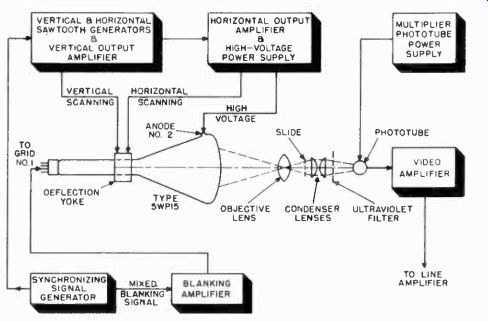
Figure 101. Block diagram of flying spot signal generator.
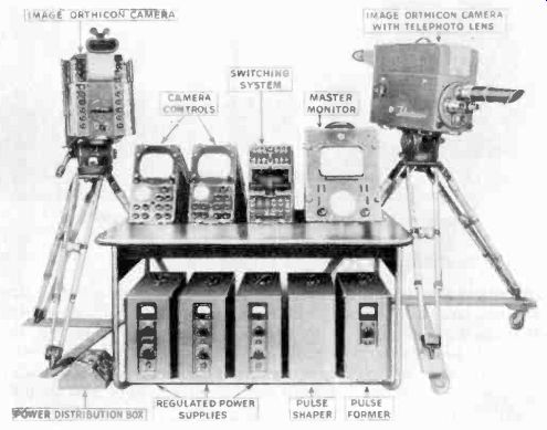
Figure 102. Field pickup camera chain. (courtesy RCA)
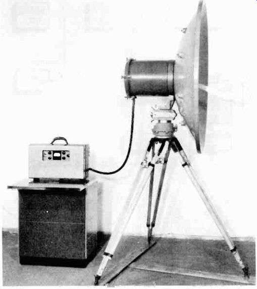
Figure 103. Microwave relay transmitter. (courtesy RCA)
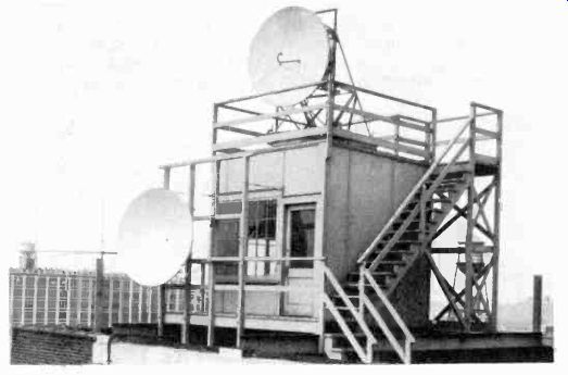
Figure 104. Permanent installation of microwave relay antenna.
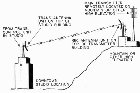
Figure 105. Typical use of microwave relay equipment between studio and transmitter.
4-86 Microwave Relay Equipment. RCA's microwave relay equipment operates in the 6,800 to 7,050 Mhz. band. The general arrangement of the transmitter and antenna is shown in Figure 103. The antenna is a four foot metal parabola which focuses the power, fed to it by a hook shaped waveguide, into a narrow beam. The transmitter is enclosed in a cylindrical weatherproof housing which is rigidly attached to the back of the parabola. This arrangement requires a very short transmission line between the transmitter and the antenna and eliminates the matching and loss problems which are encountered when a transmitter and antenna are located at different points.
The combined transmitter-antenna assembly is provided with either of two types of mountings. One of these, shown in Figure 103, is a rotatable type which allows the parabola to be moved through a wide arc, either horizontally or vertically. When the equipment is used in portable form for field pickups, the assembly maybe mounted on a heavy tripod as shown here. For fixed use, a more permanent mounting, such as that shown in Figure 104 may be used. This type of permanent installation can be used between a studio and transmitter which are not located in The power supply and operating controls of the transmitter are contained in a small case which may be located as much as 400 feet from the transmitter-antenna unit. Thus, for field use, the transmitter-antenna assembly can be placed on a high point, such as the top of a stadium, while the control unit is located at a more convenient point (with the camera control and switching units). Such an arrangement is shown in Figure 106.
The arrangement of the receiving components, is similar to that of the transmitter. The antenna is identical, except that the parabolic reflector picks up the signal and the waveguide feeds it to the receiver unit mounted on the rear of the parabola. The receiver unit includes the heterodyne oscillator, first detector, and four IF stages. The signal, at the IF frequency, is fed from this "pre-amplifier" to the remaining stages of the receiver which, along with the receiver operating controls, is located in the receiver control unit. This unit, like the transmitter control unit, is a separate case which can be located as much as 200 feet away. The receiver control unit utilizes a separate power supply, which is mounted in a similar sized case.
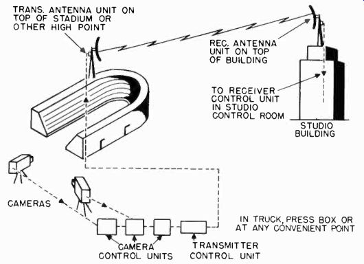
Figure 106. Microwave relay from remote pickup point to studio.
The control unit receives the signal at IF frequency, detects and amplifies it, and feeds the video signal to the master control room.
4-87 Mobile Television Unit. The RCA mobile television unit is virtually a complete television studio on wheels. It carries a complete image orthicon camera chain and microwave relay equipment. The floor plan shown in Figure 107a, illustrates how this mobile unit stores the equipment and serves as a studio control room.
In action, the mobile unit appears as in Figure 107b. The camera and relay antenna may be mounted on its roof. The camera may also be located as much as 1,000 feet away. The director usually monitors the camera in the mobile unit and sends instructions to the camera operator over a telephone line.
4-88 The Video Transmitter. The RCA Model TT-5A transmitter utilizes high level modulation. It generates 5 kw. of peak video power. In the RCA design, the undesired portion of the lower sideband is removed by a filter in the antenna circuit.
A block diagram of the RCA transmitter is shown in Figure 108. The RF section consists of a crystal oscillator, doubler, tripler, buffer (or tripler when used for the upper television band of 174-216 Mhz.) and power amplifier. These stages employ conventional tank circuits, and all but the power amplifier stage are condenser tuned.
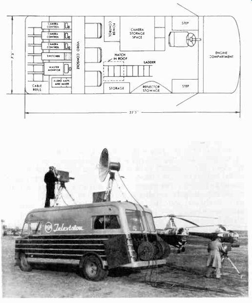
Figure 107. (A) Floor plan and (B) exterior appearance of mobile television
unit. (courtesy RCA)
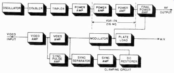
Figure 108. Block diagram of TT-5A transmitter.
An RCA 1614 tube is employed as a crystal oscillator with its plate circuit tuned to twice the crystal frequency. A 4E27 doubler with tuned input and output circuits follows the oscillator.
This doubler feeds a 4E27 tripler, which is in turn inductively coupled to the tuned grids of two 4-125/4D21 tubes operating in push-pull. For the frequency range of 54-88 Mhz. (channel 2 to 6), the push-pull stage drives a 8D21 final power amplifier tube.
However, for channel 7 to 13 it becomes a tripler, and two additional RF stages are inserted to provide adequate drive for the power amplifier. The additional RF unit utilizes two 4-125/4D21 tubes in push-pull, driving a pair of 4C33 tubes, also in pushpull. Sufficient shielding within the 8D21 final power amplifier tube and between the input and output circuits of the amplifier stage eliminates the need for neutralization.
Power is coupled from the power amplifier plate tank to the series-tuned output tank, and from there it is fed to the transmission line.
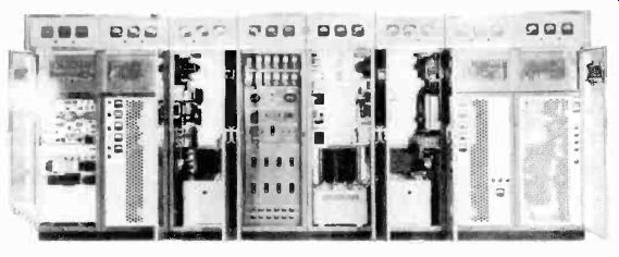
Figure 109. RCA TT-5A transmitter. (courtesy RCA)
The picture amplifier and modulator unit consists of two video amplifier stages, the modulator stage, sync expander, sync separator, sync amplifier, and a d-c insertion diode. The gain of the video amplifier is very high (about 600). This high video voltage is necessary in a high level modulation system.
Three 6AG7 tubes in parallel comprise the first video amplifier stage. From this amplifier, video signals pass through a high-frequency compensating network to the second video amplifier which consists of two 807 tubes connected in parallel. To compensate for loss in sync pulse amplitude occurring in the succeeding modulator and power amplifier stages, a 6AG7 tube is connected in parallel with these 807s. As the 6AG7 has a high transconductance (and sharp cutoff), it expands the synchronizing pulse without increasing the amplitude of the picture signal.
Six RCA 4E27 tubes in parallel modulate the grids of the power amplifier. A "clamp" type d-c restorer circuit is used in the modulator stage. This clamping circuit reduces spurious low frequency signals such as microphonics, power supply surges, and 60 cycle hum introduced in preceding stages to negligible values. Modulator bias is automatically brought to the same predetermined value for each blanking pulse, and in effect, the d-c component is restored.
Plate and screen voltages for the picture RF portion of the transmitter are furnished by power supplies located in three racks. These power supplies include a 5,000 volt d-c supply for the plates of the power amplifier, a regulated 800 volt d-c supply which furnishes screen voltages to the power amplifier, and a 1,500 volt supply for the plates and screens of the oscillator stage, the frequency multipliers and drivers. Modulator plate voltage is supplied from a 1,000 volt supply using six 8008 rectifiers.
The RF stages and the modulator occupy the last six racks of the complete TT-5A transmitter shown in Figure 109. The first two racks contain the sound transmitter which will be described later.
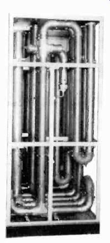
Figure 110. Vestigial sideband filter. (courtesy RCA).
A vestigial sideband filter, which is a permanently tuned RF filter that clips off a portion of the lower sideband of the 9-megacycle television signal (after modulation), and passes on to the antenna a signal which will occupy a bandwidth of no more than 6 megacycles, is used with the transmitter. The filter is contained in a completely enclosed metal cabinet. Since filter components of the common coil and condenser type would be difficult to manufacture and uneconomical to use because of the currents, voltages and reactances involved, the sideband filter has been designed with low loss coaxial transmission line elements.
(Figure 110). Water, flowing through the filter, dissipates the power absorbed from the lower sideband.
A dummy load is supplied with the TT-5A transmitter to terminate the output of either the picture or sound transmitter and allow absolute measurement of the power output of either transmitter.
The dummy load is a high attenuation coaxial line which is matched to the 72 ohm transmission line. The inner conductor of the load is a water cooled resistor. Power output is measured by the calorimeter method (described under Operation and Maintenance at the end of this section), making use of two thermometers and a flowmeter.
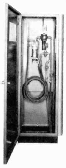
Figure 111. Power output measuring equipment. (courtesy RCA)
The load, power measuring equipment, and flowmeter are housed in a single cabinet. (Figure 111). When the load is to be used, it is taken from the cabinet and connected to the transmission line. Utilizing the transmitter water-cooling system, two 15 foot water hoses carry the water between the cabinet and load. The flowmeter is provided with an interlock to shut off the transmitter if water fails to circulate. The transmission line is equipped with quick disconnect fittings, allowing the load to be placed in operation in a few minutes.
4-89 The Sound Transmitter. The tube complement and circuits of the sound driver and power amplifier are identical to those of the picture driver and power amplifier. The exciter circuits for the frequency modulation sound, of course, differ.
The carrier frequency for the sound channel is higher by 4.5 Mhz.
A simplified diagram of the FM exciter appears in the lower portion of Figure 112. Audio signals are fed to the primary winding of an input transformer and passed to the push-pull grids of two 6V6 reactance modulator tubes. The plates of these tubes are connected in parallel to the tank circuit of a 6V6 Hartley oscillator employing a tuned tank coil. Energy from this tank coil is link-coupled to the tuned grids of the reactance modulator, one of which functions as a capacitive reactance and the other as an inductive reactance across the oscillator tank circuit. Since the amplitude of the reactive plate current of the tubes is proportional to the amplitude of the signal on their grids, application of an audio signal shifts the frequency of the oscillator at an audio rate.
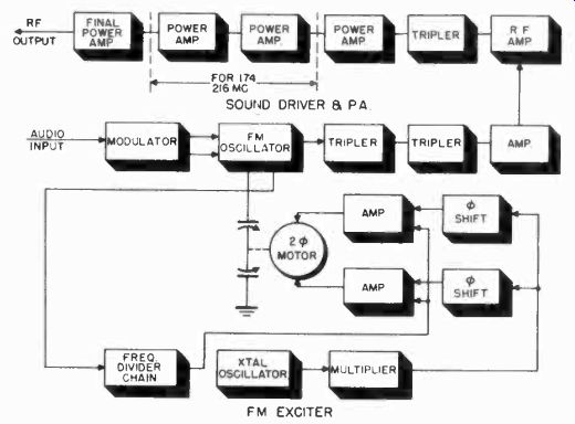
Figure 112. Block diagram of RCA sound transmitter.
The frequency modulated signal then passes through two frequency multipliers (triplers) and an amplifier which is coupled to the first amplifier in the driver stages of the transmitter.
The FM exciter unit obtains its operating voltages from a regulated power supply. Plate and screen voltages for the RF driver are furnished by a 1,500 volt supply identical to that of the video RF driver. The power amplifier plate voltage is furnished by a 5,000 volt supply, which is identical to that used for the video power amplifier. The FM exciter, driver and power amplifier shown in Figure 112 occupy the first two racks in the TT-5A transmitter.
The video and audio transmitter are coupled to the same super turnstile antenna through a diplexer. This snit was described previously in this section.
STATION OPERATION AND MAINTENANCE
4-90 Operating and maintaining the station studio equipment and transmitter is a task requiring careful coordination of the activities of the program department and engineering staff. The crew and equipment used in rehearsals is, in most cases, the same used to put the show on the air. Few stations can yet afford extra rehearsal crews, cameras, and equipment. Little time is left, therefore, for actual maintenance and adjustment, and maintenance procedures must be carefully carried out between rehearsals and on-the-air periods.
Station maintenance procedures can be broken down into two main jobs. One is the adjustment of the studio equipment, including cameras, lighting, sound system, control monitors, and synchronizing generator. The other is maintaining the transmitter and antenna in proper working order. The manner in which station maintenance and operation is carried out by the personnel of a television station may be appreciated by a brief examination of a typical day's operation.
The early part of the day is usually consumed by rehearsals and perhaps a few morning or afternoon shows. During rehearsals, the program director works out the proper placement of microphones with the technical director, the sound man, and the mike man, so that each scene is planned to give the best audio pick-up with the least amount of studio noise. The program director also plans the placement of lights with the performers, technical director, the light man, the camera operator, and the video engineer (who watches the studio scene on the control room monitor while lighting variations are tried). The planning of a set arrangement by the director during a rehearsal is shown in Figure 113.
The studio stage manager sees that the performers are properly guided on and off stage at the correct time and that props are in their right places. He must also plan scenery shifts without disturbing the cameras and mikes which are in use.
While this activity is taking place on the set, the cameras must be ON and ready to move at the director's command, in order to try out various combinations of lighting, set arrangement, and placement and appearance of performers. There are also intervals when the cameras are idle, as for example, during scene shifts or breaks in the performers' rehearsal of lines and action sequences. During these periods lens caps are placed over the lenses to protect the pick-up tubes from damage. A concentrated light beam, such as a spotlight, shining directly into the lens for a period of time will burn the photosensitive surface. To avoid unnecessary use of equipment, the video engineer must find out beforehand from the director how much of the rehearsal is to be utilized as a camera rehearsal and how much for routine study of lines by the actors.
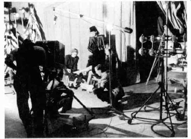
Figure 113. Planning set arrangement during rehearsal. (courtesy RCA)
Since the light man, camera operators, mike man, and stage hands are moving about the set when a show is on the air, rehearsals must include arrangements for moving props and equipment quietly without fouling camera, mike, or light cables. To be ready for this activity, the video engineer tests and adjusts the cameras and equipment at least an hour before rehearsal or air time.
4-91
The Studio Control Room. Each studio has its own control room, which is responsible for the proper operation and control of the cameras and microphones. The studio control room feeds video and audio signals to the master control room where they are coordinated with signals from other points.
Master control sends driving signals to all local studios for use in synchronizing cameras to the same sweep frequency, so that they may be switched on or off the air at will. The driving signals are fed to each camera in a studio through the studio control room.
There is one picture monitor in the studio control room for each camera in the studio. Each monitor is operated by a video engineer who works with the camera man to obtain a picture with proper focus, contrast, and brightness. As a rule two or three cameras are operated simultaneously from different locations. The program director, sitting behind the video engineers, observes all the monitors and chooses the picture which best suits the action at any given moment. The picture chosen is switched by the technical director onto the line to master control. A few moments later, as the action on the set changes, this camera may be switched off the air and another switched on.
All cameras must, therefore, be in readiness at all times during a program, and the video engineers in the control room must constantly adjust the camera signals to produce the best possible pictures on their monitors.
The video engineers in the studio control room have access to four camera controls which affect the picture quality: the electrical focus, the sweep linearity, the signal level, and the shading when iconoscope cameras are used. The electrical focus and sweep linearity adjustments are made before going on the air. The signal level and shading must be constantly varied during operation.
4-92 Electrical Focus. The electrical focus is adjusted by first optically focusing the camera on a uniformly illuminated test pattern (this pattern is usually printed on a large card which is mounted on an easel and kept in a convenient place on the studio floor.) The video engineer adjusts the electrical focus by watching the pattern obtained on the picture monitor.
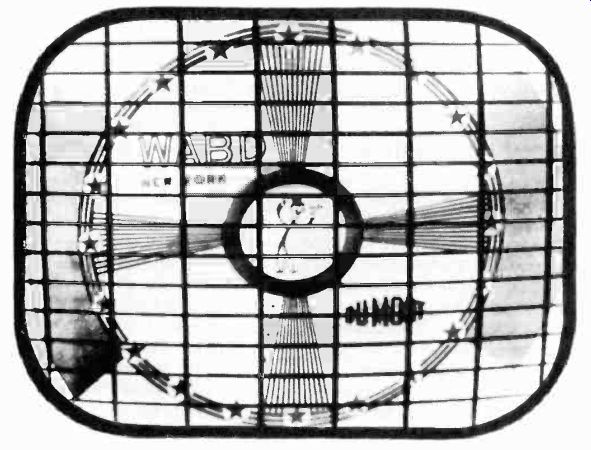
Figure 114. Linearity bars for adjustment of monitor sweep linearity. (courtesy
DuMont)
In order to obtain the best camera tube beam focus for highest resolution, it is frequently desirable to expand the picture monitor tube scanning considerably so that the wedge which runs vertically is spread out to a point where the spot size of the monitor cathode-ray tube is no longer an important factor. Another way of achieving the same result is to decrease the camera tube scanning to one half amplitude. In either case, a wedge designed to give 500 line resolution for a fully scanned picture will be, effectively, a thousand line wedge. With reduced scanning in the camera or with an expanded monitor picture, it is possible to precisely adjust the camera tube focus.
4-93 Sweep Linearity. The sweep signals controlling the motion of the scanning beam in the camera pick-up tube must be adjusted for best linearity. If a camera's sweep is not linear, moving objects in the picture will be foreshortened or stretched as they move across the screen. The linearity is checked with special calibration pulses which are received from the master control sync generator and are switched into the video amplifier circuits when needed. These pulses are derived from the divider stages in the sync generator and are called linearity test bars. They appear on the picture monitor as shown in Figure 114. The pulses are fed to the studio monitors from master control in order to obtain uniform linearity on all cameras in the station.
The picture monitor is first checked for absolute linearity by measuring the distance between linearity bars with a calipers or scale, and then making necessary adjustments of the sweep linearity controls. When the monitor sweep is linear, both vertically and horizontally, the camera test pattern is switched onto the monitor. If the pattern appears non-linear, the camera scanning circuits are adjusted.
Without linearity bars, it is difficult to determine whether poor linearity of the picture, as observed on the monitor, is caused by faulty scanning in the camera, or in the monitor, or by a combination of both. It is entirely possible to obtain a linear test pattern on the monitor if the non-linear scanning of the monitor cancels the non-linearity of the camera sweep. Such a pattern would appear non-linear at the receiver. The test bars insure that the picture being transmitted is always linear.
4-94 Adjusting the Signal Level. Because of variations in camera tubes and amplifier circuits, the output signals of all cameras are not of the same amplitude. The picture contrast will therefore change as different cameras are switched on the air, even though all the cameras are focused on the same scene.
This undesirable condition is avoided by adjusting the amplitude of the signals from each camera until all the monitors have pictures of equal contrast.
Sometimes it is desirable to create special effects in the picture electronically. For example, a night scene maybe "faked" with the studio fully illuminated to obtain maximum contrast in the picture. In the studio control room the video engineer adjusts the d-c level of the video signals so that it drops down near the sync, or black, level. The picture then appears on the monitor as though it were picked up at night.
Another special effect requiring adjustment of the signal level by the video engineer is the superimposing of the picture from one camera on the picture received from another camera. An example of this effect is the portrayal of a person having a dream. One camera is focused on the person while another picks up the scene about which he is supposedly dreaming. When the two signals are combined in the control room, the picture shows the scene superimposed on the performer. To accomplish this effect, the signal from each camera must be reduced in amplitude so that the total signal from the two cameras adds up to the signal level of a single camera adjusted for proper contrast. If this level is exceeded, too strong a signal will be fed to the transmitter. The proper signal levels are adjusted in rehearsal to secure the desired effect as observed on a picture monitor. The signal amplitude of the combined camera signals is then noted on the oscillograph monitor. If the maximum level has not been exceeded, the video engineer notes the setting of each camera. When the show is on the air and the program director calls for the special effect, the gain controls are set to the previously calibrated positions, and the combined signals fed to the same line.
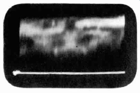
Figure 115. Waveform of properly shaded video signal as it appears on waveform
monitor with 30-cycle sweep.
4-95 Shading the Picture. Shading of the picture is necessary only when iconoscope cameras are used. Each video engineer has a set of shading controls for his camera. These controls are usually located below the picture monitor so that he can watch the picture while making adjustments. The shading signals are sawtooth, parabolic, and sine wave voltages which occur at the vertical and horizontal frequencies. They are injected into the video signal to compensate for spurious secondary emission from the iconoscope mosaic. Since this emission changes the light patterns which fall on the mosaic, the video engineer must constantly adjust the shading signals as the action on the set progresses. To enable him to determine the correct amount of shading signal to inject into the circuit, the engineer must watch two oscillograph monitors located below or on each side of the picture monitor. The time base frequency of one of the oscillograph monitors is set at 30 cycles per second and is so phased that a complete field appears in the middle of the screen as shown in Figure 115. The fact that the tops of the video signals reach approximately the same level indicates that a uniformly illuminated picture will be produced on the picture monitor. The time base frequency of the other oscillograph is run at half the horizontal scanning rate, or 7,875 cycles per second.
The video signals of successive horizontal lines appear on this monitor as shown in Figure 116.
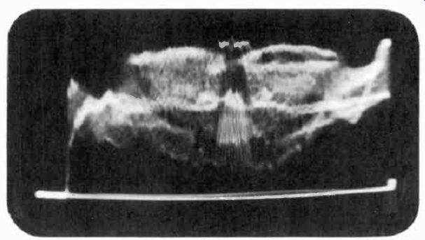
Figure 116. Waveform of properly shaded video signal as it appears on waveform
monitor with 7,875-cycle sweep.
These oscillograph patterns are very useful in shading the picture. For example, if the engineer inserts a sawtooth shading voltage at horizontal frequency into the video amplifier, the top of the pattern shown in Figure 116 slopes downward from left to right, instead of being relatively flat. This darkens the right hand side of the picture since the video signals occurring near the end of each line have an additional sawtooth component which moves them toward the black level. By inserting a horizontal frequency sawtooth voltage of opposite phase, the engineer can darken the left side of the picture. Or he may use a sine wave, a parabola, or any combination of these signals to compensate for spurious secondary emission, and thus obtain uniform distribution of light across the picture. This condition is indicated by a relatively flat-topped pattern on the oscillograph monitor.
Correct shading is indicated on the vertical frequency oscillograph monitor which shows a complete field. When the top of the video signal pattern appearing on this monitor is substantially flat, the distribution of light in the picture from top to bottom is uniform.
The shading controls are generally arranged in two groups.
The engineer manipulates all the vertical controls with one hand and the horizontal controls with the other hand.
Two oscillograph monitors are used with each picture monitor for shading, one for vertical shading, the other for horizontal shading. When image-orthicon cameras, which do not require continuous shading, are used in the studio, only one picture monitor and one oscillograph monitor are employed with each camera.
4-96 The Sound Pickup. The studio control room is equipped with a sound monitoring console and switching system for putting one or more microphones on the air. A record turntable is generally found in the studio control room for working in musical backgrounds or recorded sound effects with the action on the studio floor. The sound equipment is handled by the sound engineer who works closely with the video engineers and program director to coordinate the sound and video pickups. The sound signals which emanate from the studio control room are fed over a separate line to master control.
4-97 The Master Control Room. The master control room staff coordinates and checks the video and audio signals coming from each studio, from remote pickups, film pickups, and from other network stations. The personnel in this control room are responsible for the quality of the pictures arid sound transmitted by the station, as well as the maintaining of the standards of transmission required by FCC regulations. The responsibility of maintaining close coordination between studios, film room, and field engineers is that of the master control supervisor.
The number of picture monitors in master control depends upon the size of the station. One monitor is used to check the quality of the "on-the-air" picture. Another monitor is employed to preview the picture coming from the pickup point before putting it on the air. Sometimes two or more preview monitors are used in stations having many studios and remote pickup facilities.
In addition to giving the program its final check before it is placed on the air, master control periodically checks the operation of the sync generator and makes quantitative measurements on the video signal to assure that it conforms with FCC standards. These maintenance procedures include the checking of interlace and the amplitude and shape of the sync and blanking pulses.
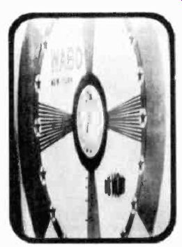
Figure 117. Vertical sweep extremely expanded.
4-98 Checking Interlace. The picture monitor is used for checking interlace. The vertical height of the picture appearing on the monitor is increased about three to four times normal, as shown in Figure 117. Expanding the picture makes it possible to see the spacing between lines. The center portion of the picture is then resolved into individual scanning lines between which the interlace can be observed. If the spacing of the lines is uniform, the interlace is correct. Poor interlace is evident when the spacing between lines slowly changes.
4-99 Checking Percent Amplitude of Sync and Blanking Signals.
The standard television signal consists of 75% picture signal and 25% sync signal when radiated from the transmitter. Generally, the transmitter modulating characteristics will compress the sync level and, to compensate for this, more than 25% sync must be fed into the mixing amplifiers. The exact percentage that is required at the master control line amplifier which feeds the transmitter is determined periodically by adjusting the sync level until an observer at the transmitter indicates that the percentages of sync and picture signal are correct. The limits of swing of the video signal, as well as the sync and blanking levels, are marked on the master control oscillograph monitor screen to correspond to the limits of swing of the radio frequency carrier and the correct percentage levels.
4-100 Checking Duration of Sync and Blanking Signals. The duration of the sync and blanking pulses is checked on the picture monitor or with a cathode-ray oscillograph. Since the sync generator can be relied upon to produce stable signals over a period of several days, only qualitative measurements are made each day before broadcasting. Experience with the equipment enables the master control supervisor to determine how often quantitative measurements and readjustment of the sync generator are necessary.
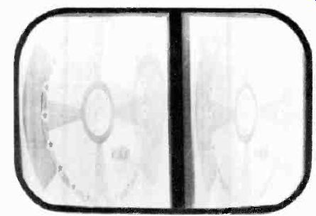
Figure 118. Test pattern with gweep at half horizontal frequency.
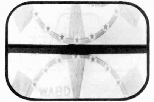
Figure 119. Test pattern with sweep set at half vertical frequency.
The duration of the horizontal sync and blanking pulses is checked by adjusting the horizontal sweep speed of the master control monitor to one half its normal frequency. Two pictures then appear side by side as shown in Figure 118. In the center of the pattern a dark vertical bar appears, which contains the horizontal sync and blanking pulses occurring between lines.
With adjustment of the contrast and brightness controls of the monitor, the blanking and sync pulses appear in different shades of grey. The sync pulses will appear slightly darker since they occur in the "blacker than black" level. The horizontal front porch, sync pulses, and back porch are then clearly visible.
The horizontal blanking region may be shown in its entirety only by this half speed scanning process. With the normal scanning pattern, a portion of the blanking occurs at the right side of the picture and a portion at the left side, making measurement of the porches and sync pulses difficult. To measure the duration of the sync and blanking signals in terms of percent of H (the FCC standards are expressed in this manner), the width of the pulse is measured with a calipers. This dimension is divided by the width of a horizontal line (the width of both half speed pictures plus the blanking interval), and multiplied by 100 to give the percent width of the pulse.
The duration of the vertical sync and blanking pulses is checked on the same picture monitor in a similar manner. While making the vertical sync and blanking pulse measurements, the vertical scanning frequency of the monitor is set at half normal, or 30 cycles per second. Two pictures, one above the other, as shown in Figure 119, appear on the monitor tube. The duration of pulses in the vertical blanking interval in terms of percent of V is measured by dividing the width of the pulse by the total height (the two half-speed pictures plus the vertical blanking interval), and multiplying by 100. 4-101 Video Signal Measurements with an Oscillograph. The measurement of the front and back porches and the duration of the sync pulses by the above method is satisfactory for day to day routine operation. However, periodically the rise time as well as the duration of these pulses must be accurately checked.
These measurements can be made precisely on an oscillograph whose sweep speed is sufficient to spread the pulse out over a large portion of the cathode ray screen.
A method for making these measurements, using a standard cathode ray oscillograph, is known as the sine wave sweep method. A 15,750 cycle sine wave which is synchronous to the pulse to be measured provides the horizontal deflection of the oscillograph. The pulse is applied to the vertical amplifier.
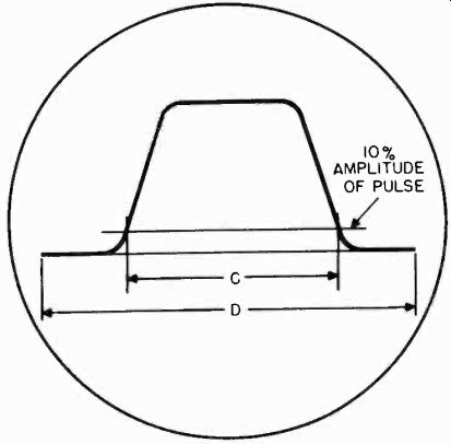
Figure 120. Sine wave sweep method of measuring pulse duration.
The pattern on the oscillograph appears as in Figure 120. With a sine wave sweep, the following relationship exists between the pulse width and the dimensions of the pulse on the pattern:
------
C
% width= siri' D 1.8
where c and d are distances measured on the oscillograph pattern.
This method of using sine wave sweep for measuring the horizontal sync pulses can be applied to the measurement of the vertical blanking interval pulses when the sine wave sweep is 60 cycles and locked to the power line.
The sine wave sweep method is tedious since it requires calculation of the final result, but is one of the few ways at the disposal of the engineer of making measurements accurately in the absence of adequate commercial test equipment. A special cathode ray oscillograph, the DuMont Type 280, is specifically designed for the measurement of all the components of the television signal. This instrument is shown in Figure 121. It permits the direct reading of the rise time and duration of the sync, blanking, and equalizing pulses within the requirements specified by the FCC.
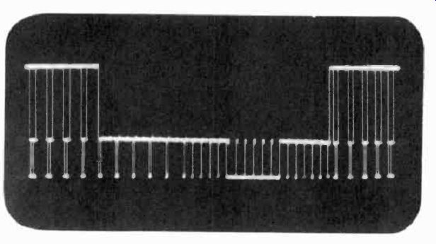
Figure 122. Vertical blanking interval. (courtesy DuMont)
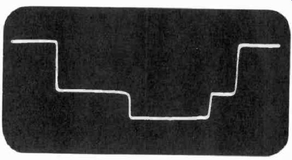
Figure 123. Horizontal blanking and sync pulse.
By feeding the composite video signal from the output of the Figure 121. DuMont type 280 oscillograph. (courtesy DuMont)
line amplifier or transmitter (picked off by a demodulating diode probe) to the input of the oscillograph, and adjusting the oscillograph sweep speed, any portion of the video signal may be examined. For example, in Figure 122 the sweep speeds have been adjusted to show the vertical blanking interval. The number of equalizing pulses may be counted to check the operation of the sync generator. By turning a calibrated dial on the oscillograph, which moves the pulse past a fixed reference point on the screen, the time duration of the pulse may be read directly.
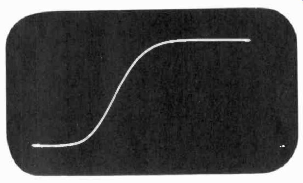
Figure 124. Leading edge of horizontal pulse.
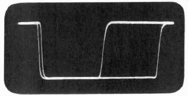
Figure 125. Superimposed horizontal sync pulse and equalizing pulse used
to check interlace.
In Figure 123 the sweep speed has been increased to select a horizontal blanking pulse. The front and back porches and sync pulse are clearly visible. The duration of each of these signals can again be read directly in microseconds by rotating the calibrated sweep dial on the oscillograph.
By increasing the sweep speed of the oscillograph still further, the leading edge of a horizontal synchronizing pulse can be expanded so as to appear as in Figure 124. With the rise time of the pulse expanded in this manner, the calibrated sweep dial may again be used to accurately measure its duration.
Precise measurements of the degree of interlace may be made with this instrument. The oscillograph is set so that it triggers on two successive fields. The patterns of both fields are then superimposed upon each other, and when the sweep speed is set to examine a horizontal sync pulse, a pattern is obtained as shown in Figure 125. This shows a horizontal sync pulse in one field superimposed on an equalizing pulse occurring in the next field. If the interlace were perfect, the two pulses would overlap. The displacement between the two is measured in microseconds on the oscillograph, and is an accurate measure of the degree of interlace of the sync signals.
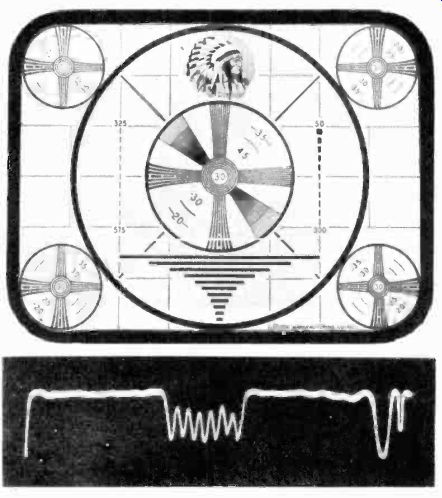
Figure 126. Oscillogram and test pattern used to measure resolution.
4-102 Checking Resolution. The DuMont Type 280 oscillograph may also be used to accurately measure the resolution of a television signal. It is capable of feeding a marker signal to a standard picture monitor. This marker signal is an exact indication of the portion of the video signal which appears on the oscillograph. On the picture monitor the marker appears as a white horizontal line as shown in Figure 126. The corresponding video signal appears on the oscillograph screen as shown in the same figure. By adjusting the oscillograph sweep circuits, the marker may be moved to any portion of the picture to examine it in detail. A group of lines may be observed as well, in which case the sweep speed is lower and the marker appears as in Figure 127. To check resolution, the operator moves the marker to the vertical wedge as shown in Figure 126. Ideally, these wedges should appear as square waves in signal form because of the alternate black and white lines. The signal actually appears as a sine wave because a 525 line television system cannot fully resolve the fine lines at the bottom of the wedge.
The amplitude of this sine wave is a measure of the degradation from the ideal square wave which would extend from the black level to the white level. Resolution is proportional to the amplitude of the sine wave.
4-103 Audio Facilities. Master control has the same audio facilities as the studio control room. The sound engineer monitors the sound signals coming from the studio to the transmitter.
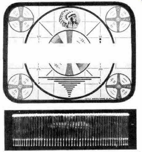
Figure 127. Oscillogram of several horizontal lines and test pattern with
marker to indicate portion of pattern used.
A turntable is available for "dubbing" in music, commercial recordings, and station breaks. The audio signal is fed on a separate line to the sound transmitter.
4-104 Operation and Maintenance of the Transmitter. After the video and audio signals are monitored in master control, they are fed to the picture and sound transmitters. Operation and maintenance procedures for the transmitters include checking of the following:
1. Carrier frequency
2. Power output
3. Amplifier bandwidth
4. Transmitter regulation
5. D-C restoration
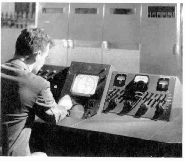
Figure 128. Monitor facilities for checking video transmitter. (courtesy RCA)
In order to observe the video signal at different points in the picture transmitter, the modulated carrier must be detected and fed to oscillograph and picture monitors. Use is made of conveniently located pickoff diodes, beginning at the first modulated radio frequency stage and going up through the intermediate power amplifier stages and the final output stage to the antenna coupling. The diodes pick off small amounts of energy from the various stages, rectify the envelope of the signal, and deliver the video signal over coaxial cables to the main monitor unit in the transmitter room. Figure 128 shows a view of the transmitter monitor rack. The monitor picture tube and the monitor oscillograph are shown. Also illustrated are the facilities for switching to appropriate circuits throughout the transmitter so as to view the pictures as they progress through the transmitter.
Such monitor facilities assist greatly in tuning up the transmitter and in determining whether or not the stages are in proper tune during normal operation.
It is important that a good picture be obtained when checking each monitor stage to assure that the overall fidelity of the transmitter is good. For example, the shape of the front and back porches and the sync pulses must be carefully maintained if proper synchronism is to be achieved at the receiver. If, however, one stage of the transmitter is so tuned that it accentuates certain frequencies, the sync and blanking pulses may have sharp tails produced by the improper tuning. Once these tails have been introduced in one part of the transmitter, they may become saturated in later stages. It is thus impossible to equalize certain signals back to the proper wave shape. The successive monitor diodes, therefore, are quite important in the initial adjustment of the transmitter and in observing its operation.
4-105 R-F Passband Characteristic. The RF passband characteristic is measured by means of a built-in or external wobbulator, whose frequency range is plus or minus 5 Mhz. about the carrier frequency. Diode pickup sampling circuits are usually installed in the plate circuit of the modulated amplifier, the cathode circuit of the intermediate power amplifier, the cathode circuit of the power amplifier, the plate circuit of the power amplifier, and in the transmission line output. An oscillograph connected to any one of these diode pickup points when the wobbulator signal is being fed through the transmitter will indicate the response characteristic of the amplifier stage.
4-106 Video Amplifier Frequency Response. The video amplifier must be capable of essentially flat response from 30 cycles to 5 or 6 Mhz. The low frequencies response maybe checked by feeding a 60 cycle square wave to the video amplifier and observing its output on the oscillograph monitor. Low frequency distortion is manifested by a tilting of the top of the square wave.
The allowable tilt in a video amplifier is about 2 percent for a 60 cycle square wave. Excessive low frequency compensation of the video amplifier stage is observed on the oscillograph as a rise in the trailing edge of the square wave, while insufficient compensation results in a rise of the leading edge. Each amplifier stage must be adjusted separately so that it is flat. Staggering the response a number of stages to give an overall flat characteristic may result in objectionable phase shift in the transmitter and is therefore avoided wherever possible.
The high frequency response of video amplifiers is checked by means of an oscillograph and wobbulator whose output is linear from about 200 khz to 8 Mhz. The high frequency peaking coils are adjusted until a frequency response characteristic is obtained which is flat to at least 5 Mhz.
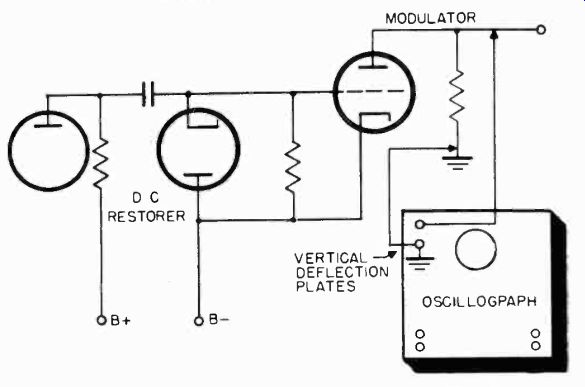
Figure 129. Method used to measure d-c restoration in transmitter.
4-107 Checking the D-C Restorer. The purpose of the d-c restorer in a transmitter is to refer all sync tips of the video signal to the same bias level in the modulator. The restoring characteristic is measured at the plate of the modulator. Figure 129 shows how the oscillograph is connected for this measurement. The signal must be connected directly to the deflection plates of the oscillograph in order to observe the d-c component.
With no video signal fed to the oscillograph, the beam on the oscillograph is adjusted to the center of the screen. The video signal is then fed to the oscillograph. The peaks of the signals which represent zero level should remain at essentially the original center position of the tube if the d-c restoration is correct.
4-108 Measurement of Transmitter Power Output. Measurement of power at high frequencies presents problems not present at lower frequencies since instruments for voltage and current measurements at high frequencies are not yet available.
In addition it is difficult to connect measuring instruments to a transmitter without upsetting its tuning.
A satisfactory method for measuring the transmitter power output without disturbing the amplifiers is known as the calorimeter method. The transmission line to the antenna is disconnected and terminated with a pure resistance equal to the characteristic impedance of the line. This dummy load is geometrically designed so that it may be coaxially installed in the transmission line. (See Figure 111) A coolant, such as water, is passed over the resistance element. The initial temperature of the coolant is first measured with a thermometer before it flows over the dummy load. It is measured again after it has been heated by the power dissipated in the dummy load. The temperature difference is a measure of the power fed to the dummy load, or the output power of the transmitter. The actual average power output is calculated from the temperature difference, the rate of flow of the coolant (measured in volume per unit time), and the specific heat of the cooling fluid. A nomograph, which relates power, temperature difference, and specific heat is then used to determine the average power output.
To determine peak power output, the above measurements are made when the standard video signal (25% sync and 75% video) is fed from the transmitter to the dummy load. The peak power is then 1.68 times the average power output as determined by the calorimeter method.
4-109 Measurement of Transmitter Regulation. The term transmitter regulation refers to the change in RF peak signal amplitude which takes place when the video content of the signal is changed from an all white to an all black picture. It gives an overall indication of the operation of the d-c restorer, the regulation of the power supplies, the stability of the a-c line, and, in general, all the equipment in the transmitter. The RF signal is observed on an oscillograph during the measurement.
The oscillograph is coupled to the antenna transmission line by a loop.
To measure the transmitter regulation, the ratio of sync signal to video signal is first adjusted to be 30 to 70 for a totally white picture. Modulation of the RF carrier is then set to give sync down to 75% of peak and white down to 15% of peak. The video signal is then changed to a totally black picture (consisting of sync and blanking only), whose amplitude is the same as for the white picture. The decrease in peak to peak RF modulation is a measure of the overall regulation. The change in peak signal amplitude from an all black to an all white picture should not exceed 10%0 of the signal amplitude with an all black picture.
The regulation is always measured with the transmitter operating under conditions of rated peak power output.
4-110 Transient Response. The fact that the transmitter amplifiers appear to have the correct frequency response when viewed with a wobbulator does not assure that they will respond correctly to steep fronted pulses. The measure of the ability of an amplifier to respond to a sharply rising pulse without introducing overshoot or sudden oscillation is referred to as its "transient response". Standards for measuring the transient response of a transmitter have not yet been established, but techniques for their measurement are being developed.
A transient response check can be obtained by feeding a symmetrical 100 khz square wave into an amplifier. The square wave must have a rise time of less than 0.03 microseconds.
To view this transmitted signal, an ideal television receiver is required, whose RF and IF amplifier characteristics will not distort the 0.03 microsecond rising square wave.
Instead of viewing the detected signal on the picture tube, it is fed to a cathode ray oscillograph whose video amplifiers can pass the square wave without distortion. Degradation of the square wave, showing effects of overshoot, ringing, and sloping of the top of the wave, give an indication of the transient response.
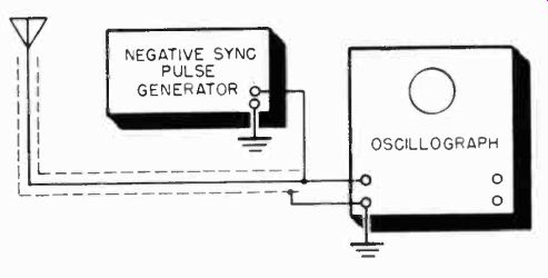
Figure 130. Method used to check antenna impedance match.
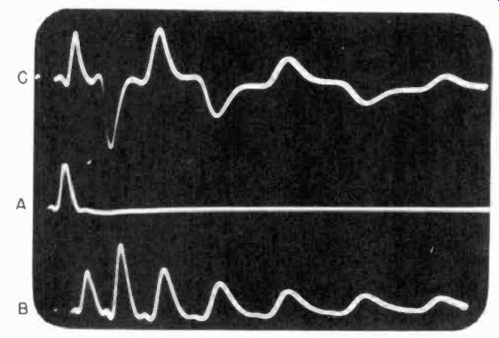
Figure 131. Oscillograms showing patterns obtained for properly and improperly
matched transmission line.
4-111 Checking the Carrier Frequency. A frequency monitor is used in the television transmitter to insure that the carrier is operating on its correct frequency. The monitor is coupled into the final amplifier stage. A crystal controlled oscillator generates the exact frequency on which the transmitter channel is to operate. This signal beats against the signal from the transmitter, producing an audio difference frequency which is amplified and applied to a frequency deviation meter.
4-112 Checking the Antenna Impedance Match to the Transmission Line. Since an antenna may be considered as a wide band tuned circuit, it should have a broadband frequency characteristic. When coupled to the transmission line coming from the transmitter, it should present a resistive load to the transmission line in order not to set up signal reflections in the line.
The impedance which the antenna presents to the transmission line is analyzed by means of a short-duration pulse generator and a high frequency, driven-sweep cathode ray oscillograph.
The connections are as shown in Figure 130. A negative trigger pulse synchronizes the oscillograph sweep and also supplies the pulse to be observed to the vertical amplifier of the oscillograph. The transmission line (at a point near the transmitter) is paralleled across the vertical amplifier input of the oscillograph. The pulse travels down the transmission line to the antenna and back to the oscillograph if the line is not properly terminated. Figure 131a shows the pattern produced when the antenna is correctly matched to the transmission line. It will be noted that only the original pulse is visible, since no reflections have taken place. Figure 131b and 131c illustrate the patterns which result when the terminating impedance is not equal to the transmission line characteristic impedance. In Figure 13 lb the pulse is reflected in phase and the impedance is greater.
In Figure 131c the pulse reflections are out of phase and the impedance is less. The antenna coupling is adjusted until these reflections disappear, as indicated by the oscillograph.