by J.R. Watkinson
The Compact Disc and its supporting equipment uses a dramatic cross-section of modern technology. The use of data converters, lasers, LSI circuits, servos, error correction, advanced channel codes, video equipment, photochemistry moulding and electroplating alone makes the CD system worthy of study by anyone interested in contemporary electronics. This series describes the system in detail and shows how many of the parameters were arrived at. Mathematics is kept to a minimum and buzzwords defined as they occur.

Fig. 7. Two schemes to separate reflected and incident light. Light from
the disc can be directed to the sensor by a semi-silvered mirror (a), or
a combination of polarizing prism and quarter-wave plate can separate the
beams (b).
Fig. 8. Moving-coil focus servo can be coaxial with the light beam. Magnet assembly is almost identical to that of a loudspeaker.
The requirement for a monochromatic light source is economically met using a semiconductor laser. The laser output requires stabilization, since the output is very temperature dependent. To prevent thermal runaway, a feedback photodiode controls the current source feeding the laser. To extract a useful signal, the pickup must be capable of separating the reflected light from the incident light. Fig. 7 shows two schemes to do this.
In (a) a half-silvered mirror reflects some of the returning light into the photosensor. This is not very efficient as some of the reflected light is lost by transmission. In the example shown at (b) the separation is by polarization. A polarizing prism passes light from the laser which is polarized in a plane at right angles to the page. This light is passed through a quarter-wave plate that rotates the plane of polarization through 45°. Following reflection from the disc, the light is again rotated through 45°, making the plane of polarization parallel to the page. The polarizing prism reflects this light into the sensor.
Stresses set up by moulding plastic can cause birefringence, so there have been some reservations about the feasibility of the second approach. The quality of disc moulding achieved, however, meant that birefringence could be neglected, and the polarizing beam splitter is used widely in the Sony consumer CD players, for example. Sony professional players and Philips players retain the semi-silvered mirror approach.
As the frequency response of he replay mechanism (unrelated to the audio response) of the spot size, care must be taken to keep the beam focused on the information layer. Disc warp and thickness irregularities cause focal plane movement beyond the depth of focus of the optical system, and a focus servo is needed. The depth of focus of the optical system, and a focus servo is needed. The depth of field is related to the numerical aperture which is defined, and the required accuracy of the focus servo follows from that: approximately ± 1µm.
The focus servo moves a lens along the optical axis to keep the spot in focus. Because dynamic focus changes are largely due to warps, the focus system must have a frequency response in excess of the disc rotational speed. A moving coil actuator is often used for this owing to the small moving mass which this permits. A cylindrical magnet assembly is used, coaxial with the light beam; Fig. 8 shows that it is almost identical to that of a loudspeaker.

Fig. 9. In the cylindrical lens or astigmatic focus method an elliptical
spot on the sensor, whose aspect ratio is detected by its four-quadrant
nature, produces a focus error signal.

Fig. 10. Knife-edge focus method requires only two sensors, but is very
critical on knife-edge position.
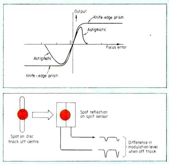

Fig. 11. Knife-edge method may have a capture range of 1mm, whereas the
astigmatic (cylindrical lens) may have a range of only 44m, requiring a
focus search mechanism.
Fig.12. Three-spot method of producing tracking error compares amplitude of side spot signals. Side spots are produced by a diffraction grating and require their own sensors.
Fig.13. Split-sensor method of producing tracking error focuses image of spot onto sensor. One side of spot will have more modulation when off-track.
Fig.14. Dither applied to readout spot modulates the readout envelope, to enable a tracking error signal to be derived.
Focus error system
A focus error system is necessary to drive the lens: Here are a number of ways in which this can be derived.
A cylindrical lens is installed between the beam spliter and photosensor, Fig. 9 its effect is that the beam has no focal point on the sensor. In one plane, the lens appears parallel-sided, and has negligible effect on the focal length. The image is an ellipse whose aspect ratio changes as a function of position. Between the two foci, the image will be circular. The aspect ratio of the ellipse, and hence the focus error, is determined by dividing the sensor into four quadrants.
Connected as shown, a focus error signal is generated. The readout signal is the sum of the four quadrant signals.
In the knife-edge method of determining focus, a split sensor is also required, Fig. 10.
At (a) the focal point is coincident with the knife-edge, and it has no effect on the beam. At (b) the focal point is to the right of the sensor. At (c) the focal point is to the left of the knife-edge and descending rays are interrupted, reducing the output of the lower sensor.
The focus error is produced by comparing the output of the two halves of the sensor. A drawback of the knife-edge system is that the lateral position of the edge is critical, and adjustment is necessary.
To overcome this problem, the knife-edge is replaced with a pair of prisms, shown at (d) to (f). Mechanical tolerances only affect the sensitivity, without causing a focus offset.
The cylindrical lens method is compared with the knife-edge prism method in Fig. 11, which shows that the cylindrical lens method has a much smaller capture range. A focus-search mechanism will be required, which moves the focus servo over its entire travel, looking for a zero crossing. At this time the feedback loop can be completed and the focus servo will remain on the linear part of the characteristic. The spiral track of CD starts in the centre and works outwards. This is deliberately arranged because there will be less vertical run out near the hub, and initial focusing easier.

Fig.15. In the Philips laser head, focus error is derived by the dual
prism method, using split sensors. Focus error (A+D)-(B+C) drives focus
motor which moves objective lens on parallel action flexure. Radial differential
tracking error is derived from split sensor (A+B)-(C+D). Tracking error
drives entire pickup on radial arm driven by moving coil.
Track following
The track pitch is only 1.6 um, much smaller than the accuracy to which the player chuck or the disc centre hole can be made. A track-following servo keeps the spot centralized on the track in one of several ways.
In the three-spot method, two additional light beams are focused on the disc track, one offset to each side of the track centreline. Fig.12 shows that the amplitude of the side spot modulation changes differentially with tracking error. The laser head contains a diffraction grating to produce the side spots, and two extra photosensors onto which the reflections of the side spots are focused. The side spots feed a differential amplifier.
A tracking error can be derived from a split sensor, because one side detects more modulation than the other when off track, Fig.13. Such a technique may be prone to develop an offset, due either to component drift or to contamination of the optical system and a further tracking system may be necessary to obviate periodic adjustment.
The dither-based system resembles in many respects the track following mechanism of C Format v.t.rs. A sinusoidal drive is fed to the tracking servo, Fig.14, causing a radial oscillation of spot position of about ±50nm. This results in modulation of the envelope of the readout signal, which can be synchronously detected to obtain the sense of the error.
The dither can be produced by vibrating a mirror in the light path, which enables a high frequency to be used, or by oscillating the whole pickup at lower frequency.
It is interesting to compare different designs of laser pickup. In the Philips laser head (Fig.15) the dual-prism focus method is used, which combines the output of two split photosensors to produce the focus error. The focus amplifier drives the objective lens which is mounted on a parallel motion formed by two flexural arms.
Capture range of the focus system is sufficient to accommodate normal tolerances without assistance. A radial differential tracking signal is extracted from the sensors as shown in the figure.
Additionally a dither frequency of 600Hz produces modulation which is synchronously rectified to produce a drift-free tracking error signal. Both errors are combined to drive the tracking system. As only a single spot is used, the pickup is relatively insensitive to angular errors and a rotary positioner can be used, driven by a moving coil. The assembly is statically balanced for good resistance to lateral shock.
In the Sony laser head, used in consumer players, Fig.16, the cylindrical lens focus method is adopted, requiring a four quadrant sensor. As this method has a small capture range, a focus-search mechanism is necessary so that when a disc is loaded the objective lens is ramped up and down while the focus circuit looks for a zero-crossing in the focus error. The three-spot method is used for tracking; the necessary diffraction grating can be seen adjacent to the laser diode.
Tracking error is derived from side spot sensors (E F). Because the side-spot system is sensitive to angular errors, a parallel-tracking laser head is essential. Cost-effective linear motion is obtained by using a rack and pinion drive fo slow coarse movements, and a laterally moving lens in the light path for rapid fine movements, and a laterally moving lens in the light path for rapid fine movements.

Fig. 16. The Sony laser head uses a four-quadrant sensor and two extra
sensors (E,F) for the side spots. Tracking error (E-F) and focus error
(A+C)-(B+D) drive the two axis device.
The same lens is moved up and down for focusing by the so-called two-axis device, which is a dual moving-coil type of mechanism. Unfortunately the two-axis device is not statically balanced in many players, making them more shock sensitive than necessary, though the problem was overcome in laser heads designed for portable players.
============
Background note on optical polarization
Polarization. In natural light, the electric field component is in many planes. Light is said to be polarized when the electric field direction is constrained. The wave can be considered as two orthogonal components. When these are in phase, the polarization is said to be linear. Where there is a phase shift between components, the polarization is said to be elliptical, with special cases at ±90° known as circular polarization.
To create polarized light, anisotropic materials are generally necessary. Polaroid material, invented by Edwin Land, vinyl which is made anisotropic by stretching whilst hot. Oriented long-chain molecules form a structure that is rendered conductive by soaking in iodine. The transmission axis is perpendicular to the direction of stretching, since electric fields parallel to the long chains are absorbed.
A material whose refractive index is anisotropic is said to be birefringent. If a linearly polarized wavefront enters such a medium the two orthogonal components propagate at different velocities, causing a relative phase difference proportional to distance. Where the thickness of the material is such that a 90° phase difference is caused, the device is a quarter wave plate. Where the plane of polarization of the incident light is at 45° to the axes of greatest and least refractive index, the two orthogonal components will be equal in magnitude, and the result will be circular polarization.
Similarly, incident circularly polarized light will be returned to the linear state. Thus linearly polarized light which has passed through a quarter-wave plate and been reflected back again will be linearly polarized but in a plane at right angles to that of the incident light. This principle can be used in conjunction with a polarizing prism that passes light in one plane but reflects light in the other plane.

LINEAR POLARIZATION Orthogonal components are in phase; CIRCULAR POLARIZATION Orthogonal components are in phase quadrative
(Adapted from: Wireless World magazine, Apr. 1985)
Also see:
Ultimate Guide to Digital Audio
Compact disc (CD) players--Theory and Servicing
= = = =