AMAZON multi-meters discounts AMAZON oscilloscope discounts
IN this volume so tar you have met a number of transducers. In Section 3 we considered some ultrasonic transducers. In Section 6 you learned about methods in counting, using transducers such as the magnetic flow meter which operated a counter. Even the cells or phototubes of Section 7 can be considered transducers. In fact, even a simple switch is one so long as it is used to convert some mechanical motion into an electrical signal for control or recording purposes. (In other words, power switches would not be transducers.) There are many thousands of special transducers suited to each particular control or recording job, all designed to convert some physical, chemical or thermal change into electrical signals. We have space only for a few, to give you the general idea of how some transducers operate, what they will probably look like on the outside and what can be done to keep them in condition, if anything.
Pressure transducers
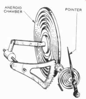
Fig. 1101. Aneroid chamber responds to air pressure. A potentiometer in
place of the pointer would make this a barometric transducer.
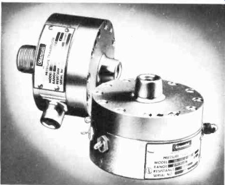
Fig. 1102. These pressure transducers use Bourdon tubes to drive potentiometers.
Most industrial processes use pressure in some phase, whether this is liquid, gas, steam or simply air. Vacuums are simply negative pressures. We have been using mechanical means of measuring these quantities for many years, and the simple Bourdon tube (the spirally -wound tube which tries to unwind if we put gas under pressure inside) and aneroid barometers are familiar to most everyone. Fig. 1101 shows an aneroid chamber bellows, and you can see that if we replace the pointer with a potentiometer and apply a dc voltage to the ends, the wiper will give us a varying dc potential, proportional to the motions of the chamber. This, in short, is the principle used in many pressure transducers; the pressure sensors shown in Fig. 1102 use a Bourdon tube with a potentiometer to do the same job.
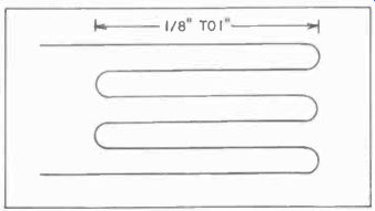
Fig. 1103. Bonded strain gage is a very thin wire cemented to a thin piece
of paper. The whole unit is then cemented to the material under test. Any
stretch of the material also stretches the wire. The increase in resistance
can be measured.
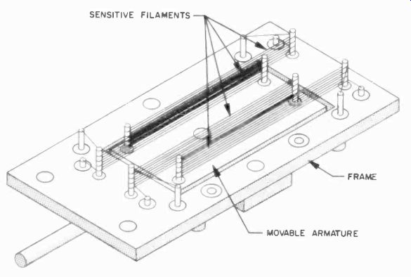
Fig. 1104. Unbonded strain gage is made of wire wound on pegs. Resistance
change is relative to the movement of the two plates. It can be attached
to a diaphragm to measure pressure.
An active element often used for the strain gage transducer, is a length of extremely fine wire laid back and forth on a piece of paper, formed into a grid which is cemented to a paper. The paper can then be cemented to any structural member which tends to change shape under the forces applied to it. Fig. 1103 shows such a bonded strain gage. Fig. 1104 shows the fine wire wound onto insulating pins. This is called an unbonded strain gage.
When the member to which the gage is attached deforms ever so slightly, the wire will be very slightly elongated also. If we add up all the bits of lengthening of all the turns, it amounts to quite a lot. In addition, lengthening the wire also reduces the cross section of the wire somewhat.
Since the resistance of the wire is proportional to its length and to its cross-section (and thus the square of the diameter), a slight elongation of the member can change the resistance of such a fine wire a measurable amount.
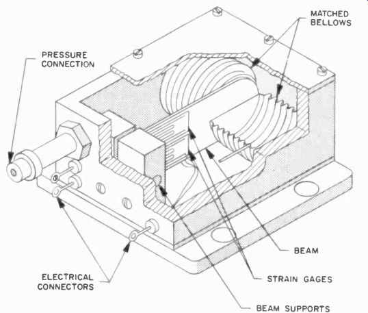
Fig. 1105. This pressure transducer uses bonded strain gages attached
to the beam, which is flexed by the bellows. Vacuum gages are also built
using this principle.
The strain gages can be set up to indicate thickening, bending or even twisting of a bar. In the pressure transducer of Fig. 1105 we use this principle by bending a small bar, with a strain gage attached, with a bellows, which we put under pressure. The resultant signal is applied to the input of a recorder.
Usually the strain gage will be one leg of bridge circuit. Most often the bridge is fed with an audio voltage, so that the signal is easy to separate from the noise and amplify in a tuned amplifier.
Another form of pressure transducer is the capacitive transducer (Fig. 1106). It is used with very high pressures such as those encountered when taking a pressure diagram of a Diesel engine cylinder and in similar applications. The capacitor is formed by the isolated electrode and the bottom "diaphragm," which is quite thick. The capacitor is part of the tuned circuit of an oscillator, changing the oscillator frequency. Or we can use it as part of a discriminator circuit, so that the change in tuning changes the amplitude of the signal in the link coil.
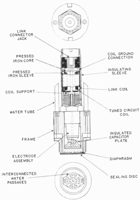
Fig. 1106. The capacitive transducer has plates connected to some form
of tuned circuit. High pressures produce minute capacitance changes. External
circuitry for this transducer is more complicated than for the potentiometer
type.
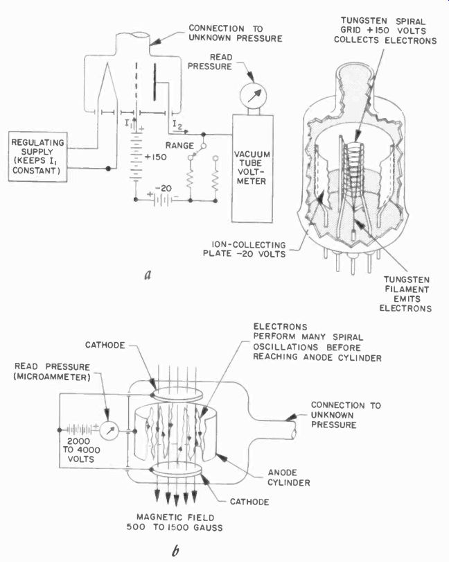
Fig. 1107. Ionization gage (a) measures the number of ions, which indicates
the gas molecule quantity left in the system. This gage can be used only
with very high vacuums as the presence of oxygen would vaporize the filament.
Note that the plate (collector) has a negative voltage to attract the negative
ions. The cold -cathode ionization gage (b) depends on many collisions
of electrons with gas molecules to form ions. This gage will not burn out
in low vacuum.
The ordinary Rochelle salt crystal forms the active element of a pressure transducer in which the crystal is deformed by a diaphragm. There are also several kinds of inductive pressure transducers. In one the diaphragm, bellows or Bourdon tube moves a core, changing the air gap in an inductor, thus changing its impedance quite drastically. Another type uses a ferrite core which moves in and out of a coil. The latter type uses radio frequencies for a carrier.
Vacuum transducers Many of the ideas of the pressure transducer can be applied to vacuum transducers. Very common in the electronics industry are the so-called vacuum ionization gages (Fig. 1107-a). The one shown appears to be just a triode. Actually, the tube is not normally evacuated, but is instead connected to a vacuum system to be measured. The cathode of the tube emits electrons, which are attracted to the positive grid. These electrons move with a considerable velocity and if they encounter gas molecules, they will ionize them: that is. stick to them and form positive ions.
These ions are attracted to the negatively charged plate, and the current on this plate is thus a measure of the number of gas molecules encountered by the electrons-in other words, the amount of gas left in the bulb. The filament is not turned on until after a substantial vacuum has been obtained, or it would rapidly burn up.
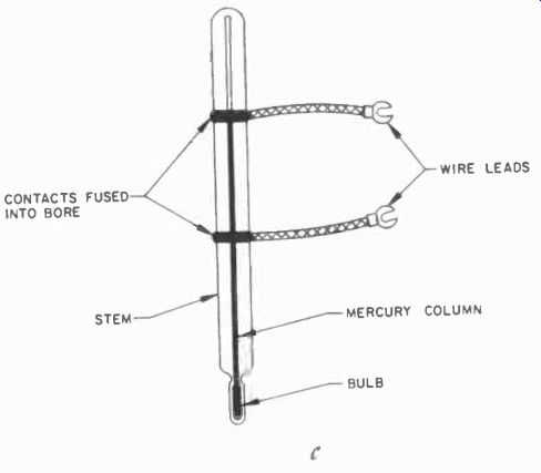
Fig. 1107-c. Contacts inserted through the glass during the manufacture
of this highly accurate thermostat complete the circuit through the mercury
column.
Although there are several improved versions of the basic ionization gage, many of the simple primitive kind are still used.
Fig. 1107-h shows a cold -cathode type.
Temperature measurement
Temperature is another quantity often measured in industry.
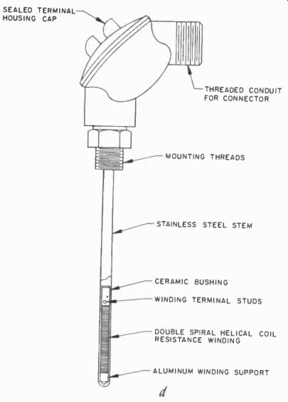
Fig. 1107-d. Resistance -change readings indicate the temperature in this
sensing element.
There are many ways to transduce temperature into electrical signals, all of them relatively familiar.
The simplest is the contact making thermometer, which closes-or opens a contact, inserted into the mercury column, through the mercury at a preset temperature. (Fig. 1107-c). Thermometers have been made with as many as 10 contacts, but these are relatively rare.
There are thermocouples, junctions of dissimilar wires. Almost any two wires can serve, but certain combinations of metal wires offer advantages. Copper-constantan and platinum-copper are a couple of the popular thermocouple combinations. Then there are thermistors, small beads, discs, wafers or rods of semiconductor material which change their resistance drastically with applied heat. Thermistors always have lower resistance when they get warmer.
Thermopiles are simply stacks of thermocouples connected in series, and thus give a much greater output. Also popular are resistance -temperature bulbs, which are wire coils installed in a protective case. Temperature is measured as a function of the increased resistance of the wire (Fig. 1107 -d).
Bi-metallic elements have been used for temperature transducers. The deformation of the bi-metallic element is used to drive the shaft of a potentiometer. Similarly, Bourdon tubes partially filled with a volatile liquid will tend to expand and straighten out, and we can use this motion to drive a potentiometer.
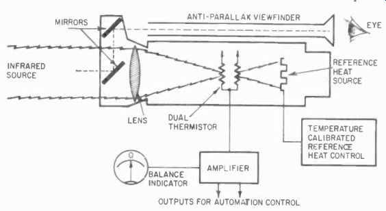
Fig. 1107-e. Infrared radiation pyrometers are useful in determining surface
temperatures without actual contact.
When selecting a particular transducer, an important parameter to be considered is the time lag. Resistance bulbs and thermistors may be quite slow in response. Thermocouples, because they are very small, may respond much faster. To get really fast response, special thermocouples in vacuum bulbs must be used. These are then pointed at the area of which we wish to know the tempera ture, and the resultant voltage measured. This is what is called pyrometry; we look at the hot spot from some distance. Optical systems often are used to concentrate heat rays on the cell. Thermistors are also used in some pyrometers. These pyrometers generally are employed only when we deal with great heat, such as blast furnaces, steel converters and similar industrial hot spots.
Some pyrometers use a bolometer as an active element. When used with the proper lens system and black -body heat or cold source reference (Fig. 1107-e) it is possible to measure temperatures quite close to ambient at a considerable distance. Adapted to astronomy it is possible to read the temperature on the surface of distant stars and planets of our solar system. The use of a reference temperature source makes it possible to measure heat or cold.
Level and position indicators
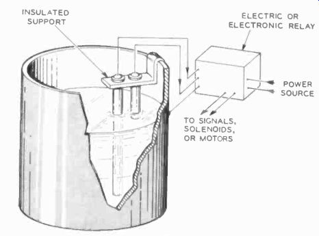
Fig. 1108. Conductivity method of measuring level.
Control can also be activated by using one rod for low level and one for high level as shown.
Levels of liquids or solids are a very important measurement in industry. The simplest liquid level transducer is a float which drives a potentiometer, either directly or through gears, belts and pulleys or linkages. These can indicate a limited level change.
Similarly limited are photoelectric devices which "read" level glasses. Ingenious designs have been used to' extend the range of float -level indicators. The float may be guided through the entire tank -level change on a rod, and the motion transferred to a potentiometer through a cable and pulley system. In another the float is made from iron and rides on a copper tube. Inside the tube is an iron core with variable pitch winding. As the float rides up and down, the effect of having an extra core section (the float) at different winding sections changes the inductance of the winding.
More directly electronic are the conductance and capacitance methods of level indication (Figs. 1108 and 1109). Almost every liquid, except transformer oil which is a very good insulator, is conductive to some extent. If we immerse a set of rods in the liquid and measure the resistance between them, the resistance is an indication of how much of the rod length is inserted in the liquid, and thus is a measure of level. Often the tank serves as one electrode.

Fig. 1109. Capacitive methods for measuring level. The insulated rod inserted
in the conductive fluid at left serves as one "plate" of a capacitor.
At right, the concentric electrodes (insulated from each other) act as
a capacitor with changing dielectric when a nonconducting fluid rises between
them.
Capacitive level indication can be done two ways, one for con ducting liquids and one for insulating types. In the conducting kind, we simply insert an insulated (coated) rod in the liquid, while the liquid forms the outer "plate" of the capacitor. For insulating liquids, we must insert two concentric electrodes, and the capacitance between them is changed by the variation in dielectric as the liquid rises between the electrodes.
More sophisticated are the sonic level indicators. These depend on the principle that, if we send a sound through a boundary layer, a considerable portion of it will be reflected. Thus if we send a sonic pulse from a transducer down onto the surface of a liquid (Fig. 1110), the time needed for the echo to return to the transducer is a measure of the depth of the air space above the liquid.
We can, of course, turn things around and send the pulse down through the liquid, but the first method is more accurate. The pulse of sound takes longer to travel through the vapor than the liquid, and therefore it is more accurate to measure the longer time interval through the vapor.
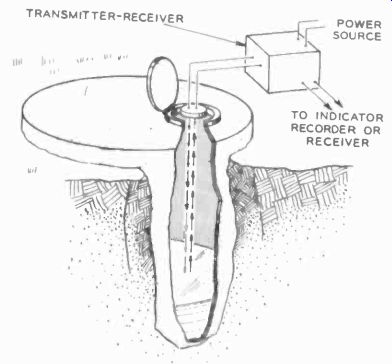
Fig. 1110. Sonic level indicator sends high -frequency sound pulse to
boundary layer where it is reflected.
Time difference between pulse and echo is measurement of level. Sound can also be sent through liquid but this is less likely to be accurate.
Radioactive level indicators depend on the amount of radiation absorbed by a liquid from a very weak source of radiation (Fig. 1111). A Geiger counter measures the radiation passed through, again a measure of the thickness (level) of the liquid.
The conductance method can be used for solids if the material is finely divided and has some conductance. Often we are merely interested in whether a bin or hopper is full or empty. In that case, we can get by with a simple indicator which has a flexible diaphragm operating a microswitch as the pressure of the material moves the diaphragm.
Another way to tell the level of solids in a bin is to weigh the bin, and for this we sometimes attach load cells with a strain gage in some structural member of the bin, and read the weight as a function of the strain on the load cells.
Moisture
Moisture can be measured in several simple ways. One uses a resistance electrode formed from a cup with an insulated section of grid inside it, and the entire cup filled with ordinary table salt to just above the grid. Salt will absorb moisture from the air, and the wetter the salt, the greater the conductivity. A simple bridge circuit can be used to measure moisture this way. The salt transducer has the disadvantage that it must be dried out periodically or the salt replaced.
In place of the salt cup, a moisture-detecting element can be used. A conductor pattern is printed on a special absorbent plastic material. It does not absorb much moisture and it does not need to be dried out with heat.
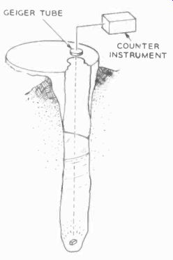
Fig. 1111. Radioactive level measurement uses low-grade radioactive source,
measures absorption by column of liquid.
Another way to measure moisture is to compare the temperature difference (by resistance measurement) between two thermistors, one in the air and a second near the first but surrounded by a sleeve which absorbs water from a reservoir. The dry thermometer indicates room temperature. The wet bulb, as it is called, shows a temperature which is dependent on the evaporation of the water from its sleeve, which in turn is dependent on the relative humidity of the surrounding air (Fig. 1112). Error is introduced in the last method by moving air currents, and the wet bulb must be kept out of drafts.
Industrially, if we wish to measure the moisture content of a product. numerous methods are available and the choice depends mostly on the shape, size and average moisture content of the product.
One method is to measure the dielectric constant of the material.
For this we must know the moisture content of various samples of the material and make a graph of the dielectric constant vs moisture. After that, we can pass the product between two capacitor plates and measure moisture content that way. This is a particularly handy method when the product is in the form of large or continuous sheets, such as textiles, paper, rubber sheet, plastics, thin wood veneer, etc. If the moisture content of such a product is high, a better job can be done by measuring its conductance.
For this we use a set of prong electrodes, rugged but small, which are spaced a fixed distance apart. To measure, the small prongs are inserted into the material all the way, and the resistance between them measured. Again some previous calibration is needed.
This can easily be done on standardized samples by weighing them: measure a completely dried out sample and weigh with a delicate balance the increase in weight with moisture absorption, measure the sample's conductance, and thereafter work with conductance only. Periodically, weighed samples, taken to assure uniformity of other factors in the process, are sufficient to make the measurement reliable.
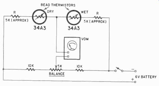
Fig. 1112. Wet and dry bead thermistors re place thermometers in this
humidity test.
Viscosity
The viscosity of a liquid or semi -liquid in industry is an extremely important factor. Viscosity tells us, so to speak, how well a liquid will flow. There are easy ways to measure this. Take a paddle on a motor driven shaft, rotate the paddle in the liquid, always at the same depth and we can measure the viscosity in two ways. Either we run the motor at a constant speed and measure the current required to maintain this speed, or we supply a constant current to the motor and measure the resulting speed. Whichever we use, either setup must, of course, be calibrated and measurements would bear a direct relationship to the viscosity of the liquid.
A flow meter ( Section 6) can tell us about viscosity, if we send the liquid through the meter always with the same "head" pressure. The flow through the meter is then related to the viscosity, with some correction for the possible turbulence created by the turbine blades in viscous fluids.
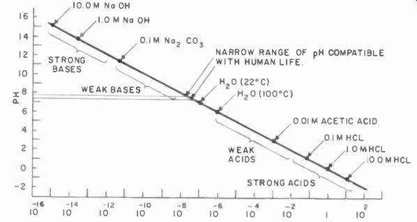
Fig. 1113. A pH .scale is a logarithmic scale used to indicate aridity
or alkalinity. A mole (M) is the number of grams per liter as indicated
by the substance's molecular weight. Note the extremely small range of
pH we can tolerate in our body fluids and stay alive.
Chemical factors
Numerous chemical factors are important in industry, and there are many ways of measuring them. One of the most important is the acidity or the alkalinity of a liquid. The importance of this is dramatically obvious if we look at a pH scale, a scale which logarithmically represents the number of free hydrogen ions in a solution, which is a direct measure of the acidity or alkalinity. On this scale we have arbitrarily called 7 a neutral solution. Numbers larger than 7 indicate alkalinity, smaller numbers acidity. Only a very small variation can he tolerated in our body fluids. We have a pH of 7.3 to 7.5 with an average of 7.4 (Fig. 1113). Beyond this lies death, through coma and the resultant cessation of functions in the acid region, and through convulsions in the alkaline region.
Small wonder then that pH measurements are important in industry, very particularly in the food industry.
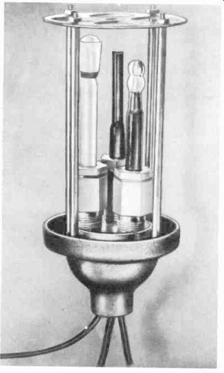
Fig. 1114-a. Glass electrode assembly used in pH measurements.
The pH factor is measured with glass electrodes (Fig. 1114-a).
The principle of the glass electrode is sufficiently complex that an entire book has been devoted to it. For simplicity we will use analogy, and try to convey the idea without going deeply into the theory.
If you dip a piece of steel in a solution of copper sulfate crystals, the steel comes out copper-plated. What happens is that some of the copper sulfate solution dissociates, leaving the solution slightly acid and some copper ions floating about. These copper ions are positive ions. Some of these will get together with the free electrons at the surface of the steel, and will form copper atoms and molecules there. You will note that the layer is never very thick, nor is it continuous, as you can see under a microscope. The steel is also partly unplated, and in these places some of the free hydrogen ions in the solution have combined with the iron electrons to Form hydrogen. In other words a sort of migration of ions takes place on the surface of the steel.
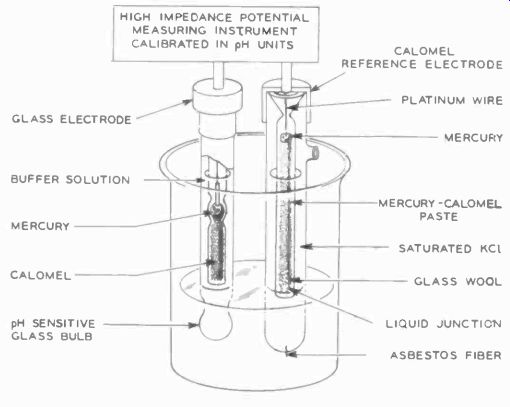
Fig. 1114-b. The glass and calomel electrodes used in pH measurements
are shown here in diagrammatic form.
The glass electrode consists of a very thin glass bulb in a weak acid (usually hydrochloric solution). Inside the glass bulb is another bulb with a strong potassium chloride solution in which a mercuric electrode is making contact. At the surface of the mercury, mercuric chloride is created, which is very high in free hydrogen ions. Thus anything happening in the outer glass bulb, as far as ions migration is concerned, does not affect the electrode contact.
The electron-ion combination (remember our example of the steel dipped into copper sulfate) releases some energy and this energy appears as a potential across the boundary layers of the electrode. Thus if we could (this is of course impossible) put another electrode in the solution which would not have any potential created at its surface, we could measure the potential at the active electrode. In the glass electrode (glass is permeable to ions) a potential is created by the ion migration taking place. The resistance of even such a very thin glass bulb is very high, and we must use special electronic means to measure it. But more than that, we must do something about the other electrode in the system. Rather than try to find an electrode which is completely inert, which we would probably never find, we go the other way and select one which always can he depended upon to produce the same potential at its surface. Such an electrode is the calomel electrode (Fig. 1114-b).

Fig. 1115. Conductivity-measurement electrode. Distance between platinum
electrodes is fixed. Vents assure that the cell fills with solution when
immersed. Conductivity is characteristic of solutions of certain concentration
and also is a factor in the purity measurement of water.
Calomel is KCL, potassium chloride, mercuric. This is so rich in hydrogen ions that whatever happens in the solution is not going to affect it particularly. The contact to the solution is made through the little asbestos fiber in the bottom of the electrode, which will soon be saturated with the solution we dip it in. The calomel electrode always produces 0.282 volt of potential at 22°C, slightly more at higher temperatures, and this gives us a handy reference for pH measurements. We now have our other electrode.
To measure the voltage developed by the electrodes we must use a very sensitive vtvm, since the resistance of the electrode is as much as 100 megohms or more and "loading" the electrodes will polarize them (the cell will act as a battery) and they recover from this very slowly. We use a vtvm which is similar to an electrometer in which the tube appears to be inverted. This circuit can measure currents on the order of 10-13 ampere, (.0000000000001 ampere), and this current across a very high resistance will provide the potential for measurement. Potentiometer type recorders can he used which are so designed that their input does not load the circuit, simply by comparing the potential in a bridge circuit.
With the bridge carefully adjusted to null, no current can flow.
The pH measurement is important in many industries beside the food, paper and textile, chemical, oil, cosmetics and drug industries, as well as medicine and biology.
Potentiometric measurements also characterize solutions other than acids and bases, and are made in a similar manner, often with the calomel electrode for reference and a silver-silver chloride one as the active element. Glass electrodes are also used.
Another measurement which will chemically classify a solution is conductance, and it is also used extensively in industry. Any organic material in the purest water will raise the conductivity.
Conductivity measurements, alongside of pH measurement, are important in analyzing both drinking water and liquid coming from sewage disposal plants. Fig. 1115 shows the electrode used for this.
To make the conductivity measurement meaningful we must either control temperature or make corrections for it. Conductivity measurement is also very important in the evaluation of steam boiler water, for too many solids or salts in the boiler would clog tubes. Special "salinity" meters, which are in effect conductivity meters, are installed in all boiler installations where water is "hard." Chemicals can be added to the water to offset the hardness, but we must first have a measurement of how much to add. On any steam vessel, the salinity indicator is an important item in the engine room where boilers are fed with evaporated salt water, which may yet contain a goodly percentage of salt even when it is considered "fit" for the boilers.
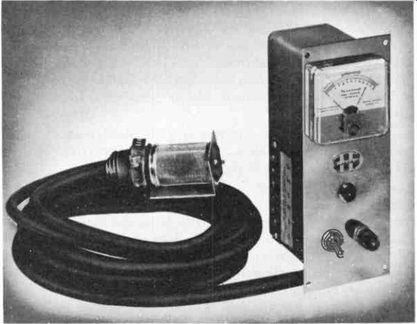
Fig. 1116. Fuel vapor detector is characteristic of a class of these instruments
used to detect gases and vapors by cooling effect on a heated electrode.
(Heath Co.)
Other chemical factors we can establish with transducers include the composition of gases and vapors. Gas or vapor, particularly in the hydrocarbon group, can often be identified by the cooling effect it exerts on a heated electrode wire. Thus, by immersing a hot platinum wire in the gas or vapor, we can determine its composition by measuring the resistance of the hot wire. Again, humidity and temperature will have their effect, but this is usually a qualitative measurement. Elaborate apparatus can be designed for quantitative measurement in this manner.
This is the principle of operation used in the Heath gasoline vapor detector shown in Fig. 1116. Numerous industrial vapor detectors operate on a similar principle.
Another method of analyzing gases and vapors is with the infra red spectrograph. There we pass a certain range of frequencies in the infrared region through a container or transparent pipe filled with the gases, and measure by optical methods which of the frequencies were absorbed most. Fig. 1117 is a set of typical infra red spectrograms of hydrocarbons. Each gas has a "picture" in infrared which is as characteristic and as different as fingerprints of human beings.
A third method of gas analyses is quite similar except that it uses ultraviolet light to give a characteristic spectrum. A fourth method uses microwaves in the same fashion.
Also used for gas analysis is the mass -spectrometer. Briefly, a mass spectrometer creates ions of the gas and accelerates them down a bent tube, using a magnetic field to bend the ion stream. Since the ions have a considerable velocity, ions of different weights will bend more or less, with the same magnetic bending forces, and will strike the wall of the tube in different places. In several places we will have collectors, where we can measure the relative numbers of ions of different weights, and thus we can establish the composition of the gas.
Gases which often need to be analyzed particularly include exhaust gases of a furnace, oven or any other process using high temperature. The presence of carbon monoxide and carbon di oxide should be known in many cases. These can be detected with devices similar to the hot-wire platinum detector, except that in the place of the hot wire we use a heated thermistor; with a comparison thermistor protected from the gas, which is at the same temperature. The difference between the thermistor resistances will indicate the presence of certain gases.
We have discussed only a few transducers; there are many others:
There are several books devoted entirely to transducers, none of which succeeds in treating all transducers. There is one for measuring practically any physical and chemical quantity from the consistency of paper pulp to the impact required to break aluminum foil or the tension that can be sustained by a nylon thread.
Every industry has its own particular measurement and control problems, and each of them may develop some special transducers for their purposes, although many will use a group of standardized types such as we have shown.
In general, the transducer applicable to a given problem must be capable of producing a varying electrical signal with sufficient accuracy and repeatability to be useful for measurement or control. The signal need not be large; we have very sensitive and ac curate recording instruments. But, preferably, it must be linear with respect to the variable to be measured, or follow some definite mathematical relationship to make the recording as meaningful and as simple to read as possible.
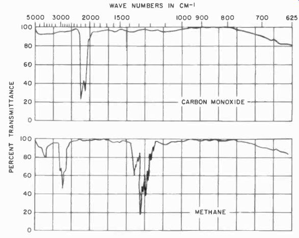
Fig. 1117. Infrared spectra can identify a great num 5er of substances
accurately. This is particularly rue of hydrocarbon gases and vapors.
Many other substances have characteristics in the microwave and ultraviolet spectrums.
Generally transducers are designed to require a minimum of service and maintenance. However, remember that, in effect, the transducer is like an extension of the instrument, and that the accuracy of the instrument can be no greater than the accuracy of the transducer. Transducers containing delicate parts such as crystals should not be subjected to mechanical shock. Delicate mechanical parts can also be damaged quite easily. Transducers must be kept clean, particularly their sensing surfaces. A photocell sooted up on the outside is not going to function properly, light just won't get through. A diaphragm thickly encrusted with salt will not give you an accurate pressure reading. So cleanliness is important, as is protection from un-warranted mechanical damage.
Other than that, not much need be done to keep transducers working.
Keeping them calibrated is another matter. Most transducers will need periodic calibration if high accuracy is to be maintained.
For example, strain gages will "creep," meaning that the cement holding the gage to the structural member may be elastic to a certain extent and may cause the gage to take a "set" so that after a particularly heavy load the gage will lose calibration. A Bourdon tube or bellows after a certain number of expansions and contractions will show a very slight change in the characteristics of the metal bellows, with the resulting in change in calibration. Most transducers are subject to wear. It depends to a great extent on the mechanical wear and chemical forces the transducer is subjected to daily. Those using wirewound potentiometers will after a time show enough wear on the pot to require recalibration, and so on.
Common sense will dictate what must be done.
Miscellaneous industrial applications of electronics We have tried to give you a cross-section of industrial applications, most of which are different from the more familiar communications practices. Items such as electronic counters, photo electric static controls, and thyratron circuits are different enough to occupy separate Sections. However these do not embrace all of industrial electronics by any means.
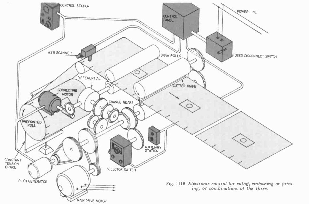
Fig. 1118. Electronic control for cutoff, embossing or printing, or combinations
of the three.
Many instrumentation and measurement practices in industry are directly borrowed from communications applications.
Thus telemetering is a very common thing in industrial electronics.
Often, available wires are used for telemetering purposes, and this is akin to the well known wireless intercom systems. We may even use such systems for control of equipment, although usually, when we start investing enough money to automate equipment, we can also afford the extra wires needed. But it is not always practical.
For example, one need of most industries is water. If a source of water supply is many miles from the main plant, it may be more profitable to handle the well -pump control by radio rather than by wire. The opportunities opened up by the new FCC rules which allow 30 watts of control power on 27.255 me may well change the balance between the economics of wire and radio control in such instances.
One very common application not yet specifically discussed is welding control. This is the control of welding current by thyratrons or ignitrons. It is similar in many ways to the Thymotrol motor -control circuit of Section 7. For arc welding, we use dc generators capable of delivering very high currents at a relatively low voltage. The voltage and the current both are important to the quality of the weld. Thus with the type of motor control rep resented by the Thymotrol we can control both the driving motor (often a three-phase wound-rotor induction type) for the genera tor and the dc circuits of the generator.
In contrast to arc welding, resistance welding is usually done with c. Here the weld is made by passing a very high current through the limited section of the materials to be welded, which is contacted by the electrodes, and the I^2R losses that are developed weld the material by heating the joint to a liquid state. The pressure of the electrodes help complete the fusion. The current is obtained from a transformer, often with but a single turn in the secondary. The secondary current is controlled by controlling the current flow in the primary of the welding transformer.
Thyratrons and ignitrons are used as switches in this case. As long as the thyratron fires with each cycle of 60 -cycle current, we have a maximum current through the transformer. By controlling the firing cycle of the thyratrons or ignitrons, we can control the average current through the transformer primary on each half cycle. By timing the firing so that the thyratron will fire on only some specific number of cycles per second, we can control the duration of the welding current. Thus for some applications such as spot welding, which is a form of resistance welding, we may use just a single pulse, depending on the material, the thickness of the work, etc. For seam welding, when the electrodes are likely to be a pair of wheels, we have a series of pulses which keeps on as long as there is material in the electrodes. In "stitching," the pulses are widely spaced: in continuous seam welding, the pulses come fast in relation to the motion of the material in the electrodes.
Electronic control in welding is an important application of industrial electronics, and one of the earliest. We cannot treat the subject in detail here, but many publications are available from manufacturers which tell the story adequately, and these can be obtained on request.
There is hardly a major industry which has not felt the impact or has not embraced joyfully the possibilities of electronics. One example is printing. There, speed and accuracy are two major requirements for the adjustment of position, pressure and tension of type, rollers and paper. This the industry has in common with many others which involves the imprinting of figures, the punching of holes, the stamping of shapes out of continuous strips of material.
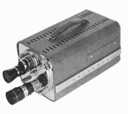
Fig. 1119. Lens turret on this camera allows rapid selection of field
of view.
Fig. 1118 shows an arrangement for accurate registry of pieces of a roll of material to be cut into sections. The system in put is the printed marks on the roll, which are scanned by the "web" scanner for the accurate positioning of the material to be cut. Similarly, the positioning of material for printing and embossing could be handled by this kind of a system. The lateral position of the material on the rolls can also be checked and corrected by such a scanner system. If the light reaches the photocell after being partially blocked by the web, the output of the photo cell will be a continuously varying signal, which can be used for the control of the web position. Another way to do the job is by turning on the cell only or obtaining from the cell a signal when a register mark passes the photocell. If the register mark does not cover the entire "seeing" area of the cell, the signal will be in pro portion to the amount of register mark that passes by-a pulsed system, in other words. Such side and longitudinal position photo electric controls are also used in printing presses, where registry must be extremely accurate when three or four colors are printed successively on the same sheet of paper.
Such register controls are also used in the printing of etched-circuit boards when the image to be left after the etching is first printed in resist type ink. The sheets of laminate are usually printed with numerous copies of a circuit to be etched, and is not cut into individual circuit boards until after the etching has been done. Registry is required not only for the multiple printing job but also for the cutting process. For mass production, the manufacturer cannot rely on the accuracy or the "squareness" of the raw sheet, and register marks are often provided on the laminate to position it properly for printing and sawing.
An entire electronic printing process, xerography depends on the depositing of charged carbon particles on a negatively charged electronic "image." The image is put on the paper by exposing it to ultraviolet light. The paper is specially treated. The process can be used for more permanent printing by fusing the carbon particles into solid "type." Another way that electronics is used in "typesetting" is in a photographic process for producing "typeset" material. In this equipment, photographic records of many type fonts are stored on film. The proper font and letters, are selected electronically as the operator "types" out copy.
Electronics is also used in engraving. A machine has been in vented which photo-electrically scans a color image, and electronically selects the portions of the image which belong on the various (three or four) color plates from which the final image is to be printed.
Industrial television
One of the important subjects in industrial electronics, but one which is fortunately not far removed from the average technician's experience is ITV, industrial television.
Two basic systems are in use. In one, the camera or its control unit generates the necessary signals, and impresses them on a carrier, which can then be received by any standard television receiver, but the signal is supplied to the receiver over a coaxial cable. Considering the sensitivity of the average TV receiver, it is obvious that the signal level in such a system can be very low.
This is in one sense an advantage, and in another sense a disadvantage. We can work with low signal levels, but we must be very meticulous about shielding out any unwanted noise which could amount to a significant part of the signal.
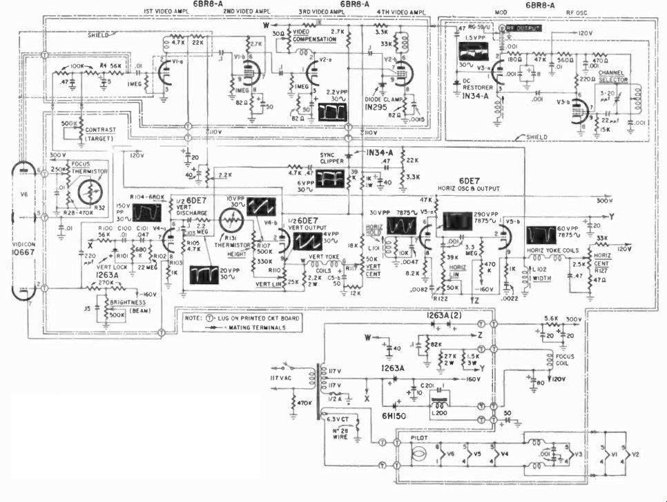
Fig. 1120. Schema of camera that can use any TV receiver as a monitor
due to the modulated carrier output.
The other system uses a special camera and control unit connected directly to monitors designed to work from the camera and control unit only. In this system, no rf carrier is generated. The sync and video signals may be transmitted over a single coax or over separate cables. This system has the advantage that it can be used in an area of interference with greater impunity, but it demands special monitors.
However, the monitors are not as complicated as a TN' receiver, for the entire tuner, if and sound sections are left out. If the sync signals are applied over a separate cable, even the sync separation circuits are not needed, and the monitors become more simple.
Another advantage of the system is that the synchronization between the camera and the monitors is direct and positive, and we can use a system with more lines to get greater definition-if we so desire. The number of horizontal lines used in commercial television is a compromise between definition and economy, and, although definition and clarity are acceptable for entertainment purposes, some scientific work could require greater definition.
For example, where we use the ITV system to broadcast (for purposes of instruction) the image seen by a camera through a microscope, definition becomes a crucial factor.
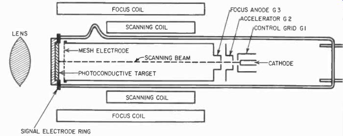
Fig. 1121. Diagram shows the basic construction of vidicon camera tube
and the positioning of the associated components.
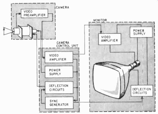
Fig. 1122. This block diagram shows the simplification when rf carrier
is eliminated.
ITV is not complex in terms of circuitry compared with the normal home TV sets; in fact, it usually is simpler. Fig. 1119 shows a typical camera of the type that can be used with any TV receiver, and Fig. 1120 is the schematic diagram of one of them. In this diagram we have a video amplifier and an rf oscillator which is modulated with the video signal. The oscillator produces a carrier which can, usually, be received on the lower channels (2 to 6) of the TV receiver. In addition, there are circuits to generate the vertical and horizontal deflection for the camera tube (Fig. 1121) which also serve to provide the sync and blanking signals for the carrier. The camera tube can be one of several types. The one shown in Fig. 1121 is a Vidicon, a photo conductive tube. As the light hits the photoconductive layer in the tube, the current at that point from the beam is greater, and consequently the signal across the load resistor is created. The rf composite signal from the camera unit is like the one produced for commercial TV transmissions.
The other system, using no rf carrier, is shown in the block diagram of Fig. 1122. This system contains a video amplifier, the horizontal and vertical sync and deflection circuits for the picture tube, and the power supplies that are all relatively conventional.
There is no rf section, no if section, etc. The camera contains only the preamplifier, while the control unit contains the necessary sync pulse generators, deflection circuits and the main video amplifier.
This kind of equipment has been developed to include all kinds of circuits to make the image a more precise reproduction of what the camera sees. Thus correction is made automatically for aperture of camera lens, which in effect means that electronically we compensate for the amount of light falling on the object we are looking at. A wide latitude of light intensity is provided for, so that the image on the monitor will be clear under many different lighting conditions, without becoming blotchy or all white-in other words, without loss of detail. In scientific work particularly, but also in industrial applications, this can be of extreme importance.
Maintenance of an ITV system is not greatly different from TV service work, but remember that you are now dealing with some thing that is not merely entertainment, but something that is depended on by the owner to provide him with certain necessary functions and that interruption of these functions may be costly to him.
Maintenance and troubleshooting data are always supplied with the equipment, and will vary so much from one environmental situation to the next that we cannot reasonably generalize about it. Be familiar with the equipment maintenance procedures before something happens.
Another area of industrial electronics not entirely foreign to the communications technician is the intercommunications net work. Here special requirements are demanded by the industrial situation, which is often noisy and sometimes very hard on the equipment. But apart from special enclosures and sometimes more power, the equipment is very similar to the commercial variety. Where the system is to be used only for voice, (paging and instructions), a frequency response of 300 to 3,000 cycles is quite adequate for intelligibility. But where the system is also to be used for music-and it will be in many industrial situations, particularly those involving a great deal of monotonous work the frequency response should range from 100 to 8,000 cycles.
All the factors of coverage, installation and protection of public address equipment will apply here, and the well known constant--voltage system is as popular for industrial systems. As you can see from these few examples, industrial electronics is an enormous field indeed. There are so many applications that we could fill many volumes trying to describe them all. Control of railway signals, radio communications within and around a plant, industrial X-ray controls, special instruments in the automotive industry, truck weighing, frequency changing for high -frequency lighting, textile mill controls, thickness gaging and fault detection in many materials of many types, wood gluing, automatic door openers, automatic elevator controls, fire and intrusion alarm systems, detection of underground pipes, automatic gas detection in mines, the automatic production and testing of electronic equipment, just to grab a handful out of the bag. All are part of industrial electronics. You will find, however, that each industry has uses for a relatively limited kind of equipment, and that complete knowledge of all equipment is almost an impossibility anyway.
The sanest approach to getting into the electronics servicing business on an industrial level is to survey carefully the area in which you wish to operate. Find out what equipment is being used, what kinds are likely to be used in the near future, and what should be used for modernization. If you are prepared to deal with most of them, you will probably have few difficulties in carrying out your plans.
Microwave cooking
The use of these ovens solely for the rapid cooking or reheating of food removes this application of electronics from the group of industrial dielectric and induction heaters of Section 3. Often new devices get their names from some similarity to a previous product or process. The trade name of a device may often become a popular reference name for all like units simply because it was the first or most advertised. For instance, the common refrigerator was long referred to by a popular trade name. Here we find radar led to radar cooking and Radarange.
While microwave cooking is a small field at the present time, there is much room for expansion. The oven is primarily a dielectric heating device since the heat occurs internally. This presents an entirely new problem in cooking. Microwave-cooked food has been compared to boiled food. Roasts do not brown. Cakes and breads do not have the familiar crust. Steaks and roasts are always well done.
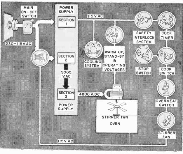
Fig. 1123. All microwave cooking devices have circuitry similar to this,
outlined in block form. (Raytheon Corp.)
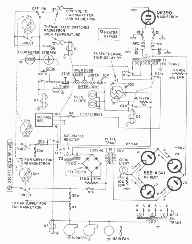
Fig. 1124. Circuitry of model 1161A Radarange is simple when compared
to TV receiver. (Raytheon Corp.)
The advent of completely frozen meals on a tray is a perfect application for microwave cooking, or rather reheating. Solid frozen frankfurters can be converted to steaming hot food in less than 2 minutes, and other foods take about as long. Conceivably the familiar steamtable could be replaced with a deep-freeze chest.
Menu items could be preformed into portions and frozen. When all the items had been assembled on a serving dish, they would be inserted into the oven, to emerge thoroughly reheated. The problems of keeping food palatable on a steamtable would be a thing of the past. There would be no waste in unserved foods. Menus could be expanded to include many additional treats. The "daily special" would no longer exist except for merchandising and advertising purposes.
Radar cooking equipment utilizes the same band of microwave frequencies as radar equipment, and has similar generating circuits and components. There are a number of radar type ovens, but, since all of them operate on the same principle (Fig. 1123) we will use the Radarange as a typical example. Fig. 1124 shows the schematic diagram. The heart of the circuit is the magnetron.
The magnetron is complicated in function although simple in appearance. The symbol for it shows a diode (although it has two or more anodes) and a single cathode, and sometimes the anode has a number of cavities built into it. An electron traveling through a magnetic field will have its path altered in relation to the velocity of the electron and the strength of the magnetic field.
In the magnetron, specially shaped to fit easily between pole pieces, a magnetic field with lines of force parallel to the cathode of the tube, is established-in other words, an axial magnetic field. Fig. 1125 shows, symbolically, a magnetron with two anodes. The lines of force of the magnetic field would be perpendicular to the paper, with the North pole above and the South pole below it.
Note what happens to an electron starting out from the cathode.
If the field is strong and plate voltage (and thus electron velocity) low, the path of the electron will curve most (Fig. 1126). The next curve is the result of a very high plate potential. Then is shown the path of an electron traveling in a little stronger field (with less plate potential), and, finally, if we make the field strong enough or the plate voltage low enough, the electron never gets to the anode and instead circles the cathode. In this case, no electrons reach the plate, and the tube is in a "cutoff" condition. In operation, the tube is actually in this cutoff condition, although some other factors must be taken into account, as will be shown.
If we have an equal plate voltage on the two anodes, the potential at any point between the plates and the cathode is the same as at any other point located at the same distance from the cathode.
If we connect these points graphically in a diagram, we would show so-called equipotential lines, concentric circles about the cathode with each corresponding to a given potential. This is, of course, an imaginary concept since the potential change is smooth and continuous.

Fig. 1125. Basic structure of magnetron is simple, with two plates and
a heated cathode.
If we lower the voltage on one of the anodes, the equipotential lines would be distorted as shown in Fig. 1127. An electron now setting out from the cathode will start with a relatively high potential pulling it out, while the magnetic field tends to curve it back. When an electron returns to the higher potential part of the field, it will not penetrate as deeply and will again be curved away. Instead of getting closer and closer to the plate toward which it started, it keeps drifting farther and farther, and finally ends up on the anode with the lower potential.
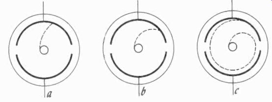
Fig. 1126. Three conditions of electron path in magnetron.
Variations are due to changes in magnetic field or applied voltages.
By lowering the plate potential of one anode, we increase the current to it. In other words, we have a negative resistance characteristic which we can exploit for oscillation purposes. This is usually done by using a resonant circuit, which could be a Lecher-wire system but a cavity type resonant circuit is more practical at higher frequencies. In another method, referred to as "electronic" operation, the electrons, in the cutoff condition, orbit the cathode (Fig. 1126). The electrons are orbited around the cathode at a velocity which brings them past each anode resonant cavity under the same magnetic field conditions (in other words, the transit time is exactly one full cycle of the cavity's resonant frequency) the electron will induce a field change in the cavity at each turn, thereby exciting it. In a multi-cavity anode, an electron excites each cavity in turn.
The orbit of the electron will be affected by the field in the cavity, since the electron gives up kinetic energy to the cavity field, which is, in effect, "lessened" by the electron and the latter is then more easily deflected from the anode. Thus, we have a multitude of asymmetrical orbits around the cathode, and a continuous interchange of energy between the fields in the cavities and the circulating electrons.
This type of oscillation, named "dynatron," can take place in different "modes." The relationship between the lopsided orbits and the cavity fields can be arranged in different ways by changing the magnetic field and the plate potentials. The energy in the cavities is taken off by stubs, which in turn excite a short wave - guide. In the Radarange, this energy is emitted directly from the waveguide to the food being cooked.
Note that the voltage of the power supply at the lower right of Fig. 1124 is regulated by magnetic amplifier T3. The magnetron is extremely voltage sensitive. As in dielectric generators, no filtering is required. In fact, a 60 -cycle input is intentionally introduced into the circuit by T2 to prevent the magnetron from oscillating continuously, which would overheat it and might even melt the glass.
The schematic diagram (Fig. 1124) shows power is supplied to the unit through the terminal block and oven control switch S1.
When this is turned on, power is first supplied to the rectifier filament transformer T2, time -delay relay K2 and magnetron filament transformer T1. The thermal element of K2 (supplied with 115 volts) delays the rest of the cycle by 75 seconds to assure properly heated filaments. When K2 finally closes its contacts, relay K3 is energized and latches in. The filament voltage on the magnetron decreases to 9 volts (it is 11 volts during warmup), and KS applies 115 volts ( through all the safety interlocks) to the stop switch, cook switch and cooking timer. This puts the range on standby, ready to cook with blowers running, all filaments warm and oven lamps lighted. When the timer is set, 115 volts is applied to the timer motor and the coil of K4 closes its contacts. The stirrer motor is now running.
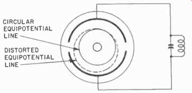
Fig. 1127. Distortion of equipotential lines by lowering the B -plus on
one anode will cause electrons to "fall" toward that anode.
On the LO position of switch S1, only one of the magnetrons is used. In the H1 position, both magnetron power supplies are energized. In both positions, relay K1 is energized. This reduces the magnetron filament to 7 volts during operation. Also, power transformer T4 is energized through saturable reactor T3. The secondary of this reactor, which is in series with the 230-volt sup ply voltage, is also energized. Voltage from T4 is automatically regulated by the reactor.
Notice that the rectifiers have no filter capacitor on the output. The power supply thus provides 4,800 volts dc, pulsed at 120 cycles. When K1 closes, the 4,800 -volt supply is connected to the magnetrons, which then generate 2,450 megacycles.
Notice also that the supply is 4,800 volts negative, allowing the anodes of the magnetron to be grounded. Because, these anodes project, inside, through the top of the oven, this is a safety feature --an operator putting his hand in the oven to insert and remove food will never contact the fatal high voltage from this supply. The magnetrons are cooled by blowers. Failure to cool the magnetron would almost certainly destroy it through over heating. Each magnetron produces 800 watts of power, and the entire range, 1,600. (On LO we have just half, or 800 watts).
When initially installed, the range is tested by heating a quart of water in a plastic container. If the range raises the water temperature 45° to 47° in 2 minutes, it working at full power. Anything more or less than that calls for readjustment.
The service manual which comes with the range is very clear and explicit about maintenance, and no purpose would be served in treating it in detail here. Only some of the highlights will be discussed.
The interlock switches particularly need a periodic check, for a sticking switch might keep the range from operating. Or, worse, it might allow the range to operate with the door open, spraying the operator with rf energy. Although this is seldom fatal, it can cause nasty burns. If the energy can cook a steak from the inside out in minutes, it can certainly raise the temperature of human tissue dangerously.
Operation with the oven empty is likely to raise the temperature of the magnetrons glass top to the breaking point. Never operate such an oven empty. Even a plastic bag of water is better than nothing.
Periodically, the cooling-air filter must be cleaned. Other cooking besides that going on in the range will not take long to foul up the filter with grease. Filters are cleaned with warm water, soap or detergent and a stiff brush.
Three kinds of magnetron trouble can develop: a gassy, a non-starting or a runaway magnetron. Gassiness may result from a minute leak in the glass-to-metal seal. A gassy magnetron will not generate microwaves and can be recognized by its using 500 ma of cook -light current rather than the usual 320 ma. This is measured at the cook light, as the instructions will make clear. Gassy magnetrons must be replaced.
A runaway magnetron may be caused by insufficient cooling and will be detected in the same way, by measuring the current.
A non-starting magnetron may result from insufficient filament voltage possibly due to poor filament connections. Cleaning the connections and refastening is often a cure.
Unstable readings on the milliameter indicates arcing, and causes an audible buzz in the oven. This calls for replacement of the magnetron, if the arcing is internal.
Apart from the magnetron, the oven contains no service -prone parts. Rectifiers should be checked periodically. The magnetron is quite voltage-sensitive, and any drastic reduction in B-supply causes failure. Be particularly alert to proper operation of cooling fans. Nothing could do damage, more quickly, than inadequate cooling, and it, like the overheating of the magnetron glass, is the kind of damage no fuses can protect against.
For other than the magnetrons, routine electrical equipment maintenance applies to the Radarange.