Counters use flip-flops and gates to provide various functions such as binary counting, decimal counting, counting up, counting down, and generating a pulse when a preset count is reached. Counting is analogous to frequency division, since an output is generated only after a certain number of pulses have been fed into the counter. Thus, you may get one pulse out for every two pulses in, or one pulse out for every ten pulses in, etc. A binary counter, for example, is essentially a divide-by-2 circuit that generates a true output for every second pulse in.
FOUR-BIT BINARY COUNTERS
Fig. 6-1 is the circuit for a 4-bit binary counter (type 5493/7493) that can be used to count up to 16 or to provide simultaneous frequency division by 2, 4, 8, and 16. The flip-flops are master-slave type; the J and K inputs are open (which is the equivalent to having is as inputs) ; and the flip flops will toggle on the negative edge of the clock pulse.
Consider first the reset function. When both Ro inputs 1 and 2 = 1, the output of the reset gate is 0, and all flip-flops are driven to 0-that is, outputs Q A through Q D = 0. In normal counting, one or both reset inputs will be a 0, giving a 1 out of the reset gate and thus allowing the flip-flops to follow the clock pulses.
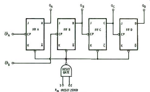
Fig. 6-1. Block diagram for a 4-bit binary counter.
Except for the reset function, the IC consists of two completely independent circuits. Flip-flop A has its own input and output, while flip-flops B, C, and D work from one input and their outputs are interconnected.
Flip-flop A provides a divide-by-2 function. ( It counts up to 2 since its output is one pulse out for every two pulses in.) Fig. 6-2 shows a master-slave, negative-edge-triggered flip-flop, such as circuit type 7473, set up to act as a divide-by-2 counter.
When the Reset button is pressed, Q goes to 0 regardless of its previous state. When the Count button is pressed, the circuit will respond as shown in the truth table. If the Count button is not operated, the flip-flop obviously stays in the reset state ( or count 0). On the first negative-going clock signal, Q goes to 1 and remains there when the clock returns to 1. The next negative-going count signal sets Q back to 0. Successive counts repeat the sequence.
If the number of pulses ( 1s) coming out of Q is compared with the number of pulses put in at the clock input, we see there are only half as many. Thus, the input frequency has been divided by 2. If a 60-Hz pulse train is applied to the clock input, a 30-Hz train comes out of Q. Flip-flop A of the counter ( Fig. 6-1) operates as described above. Flip-flops B, C, and D are similar to flip-flop A but are interconnected. If a pulse train is applied to CP of flip-flop B, the same divide-by-2 output will be present at Q B as was present at Q A. The output of flip-flop B is the clock input to flip-flop C. Thus, flip-flop C will toggle when Q B goes to 0, as shown by the waveforms in Fig. 6-3. From flip-flop C, there are half as ...
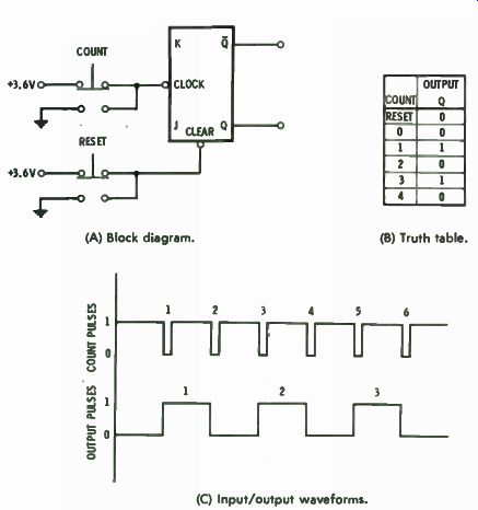
(A) Block diagram. (B) Truth table. (C) Input/output waveforms.
Fig. 6-2. Flip-flop used as a divide-by-2 counter.
... many pulses as at Q. Output Q, in turn, acts as the clock input to flip-flop D, and the output from flip-flop D is half as many pulses as from flip-flop C. So, 60 Hz applied at the CP of flip-flop B gives a 30-Hz output at Q B, 15 Hz at Q, and 7.5 Hz at output Q D. The circuit starts at 000 and returns to 000 at the eighth pulse.
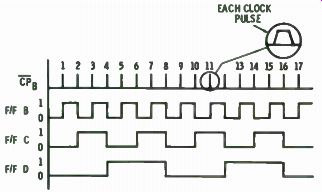
Fig. 6-3. Waveforms for Fig. 6-1.
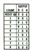
Fig. 6-4. Eight-count truth table for Fig. 6-1.
As pulses are applied at the CP of flip-flop B, we see that outputs Q B, Qc, and Q D are storing, remembering, or counting the number of input pulses. This is shown by the truth table in Fig. 6-4. The circuit can count from 0 to 7, where the binary number 000 is the first condition and the binary number 111 (which is equal to decimal 7) is the eighth condition. On the next input, the 3-bit counter overflows and the count starts over.
To count higher than 7, flip-flop A can be used in tandem with flip-flops B, C, and D. Output Q A is connected to input CPB, and the signals to be counted are applied at input P. Conversely, the inputs can be applied to UP ; and, output Q D can be used as the input to rir, ; then output Q A becomes the output of the counter. Four stages of binary counting will identify 16 numbers ( 0 through 15) as shown in Fig. 6-5.
Overflow occurs on the sixteenth count.
Binary counters can be connected in tandem to count as high as desired. Each flip-flop added to the chain doubles the capacity of the counter. It is possible to count to 32 (0 through 31) with 5 flip-flops; to 64 with 6 flip-flops; etc.
DIVIDE-BY-TWELVE COUNTERS
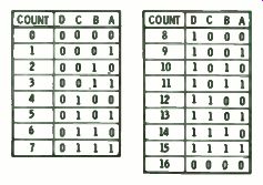
Fig. 6-5. Sixteen-count truth table for Fig. 6-1.
The binary counter considered previously provides divide by-2, by-4, by-8, etc., which are all powers of 2. In many circuits, however, division by other numbers is necessary. For these cases, binary counters with special internal interconnections and external gating can provide division by any number.
Divide-by-12 ( divide-by-2 and divide-by-six) ability is provided by a circuit type 5492/7492 IC, shown in Fig. 6-6. The only differences between this circuit and the previously considered counter are a few changes in the internal connections and the routing of the clock pulse. Reset is obtained as in the previous counter.
Flip-flop A provides divide-by-2 operation, while flip-flops B, C, and D provide divide-by-6. For divide-by-12, the two sections work in tandem, in either sequence, A before or after B, C, and D.
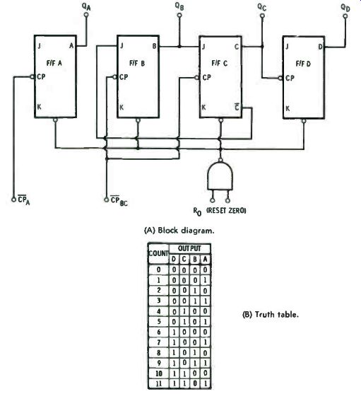
Fig. 6-6. Divide-by-twelve counter. (A) Block diagram. (B) Truth table.
Fig. 6-7 indicates how flip-flops B, C, and D provide the divide-by-6 function. The reset function sets all the outputs to 0 ( line 1). After reset and prior to the first clock pulse, the clock input can be thought of as being high (although the clock may actually be high for only a short period before the negative transition). Thus, immediately after reset, the circuit is in the state shown by line 2.
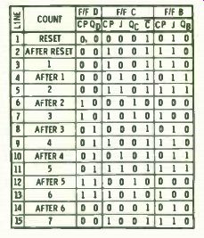
Fig. 6-7. Analysis table for Fig. 6-6
At line 3, the clock input CPBc in Fig. 6-6 goes high, which gives the same conditions as line 2. Line 4 shows the state of the circuit after the negative transition of the first pulse. output Q B has been driven to 1 (because its J and K inputs are both 1, causing the circuit to toggle). Input J to flip-flop C is also a 1; thus, flip-flop C is set up for a toggle. Flip-flop D has not been affected.
The next pulse sets up both B and C flip-flops and the state of the circuit after the negative transition is shown by line 6.
Output Q B goes to 0, Qc goes to 1, and Q D stays 0. At the same time, inputs J to flip-flops B and C go to 0, and the clock signal to flip-flop D goes high.
Pulse 3 goes high, setting up the circuit per line 7. When pulse 3 goes to 0 ( line 8), Q B goes to 0 because its J input was 0 and Qc also goes to 0 because its J input was 0. When output Qc goes to 0, it looks like a negative-going clock signal to flip flop D, operating in the toggle mode, and flip-flop D, therefore, goes to 1.
Pulse 4 ( line 10) sets outputs to: QB = 1, Qc = 0, and Q D = 1.
Pulse 5 is shown by line 12 and pulse 6 is given on line 14.
(Note that line 14 is the same as line 1, and line 15 is the same as line 2.) Thus, the circuit will repeat the above sequence as long as pulses are fed into it.
The circuit does not count up to binary 6 but counts in binary (Q D Qc Q B) as follows: 0 ( 000), 1 ( 001), 2 ( 010), 4 ( 100), 5 (101), and 6 ( 110) -binary 3 is missing. Nevertheless, six pulses are required to get one complete pulse at output Q D; thus, the circuit divides by 6.
When flip-flop A is used as the input circuit and output Q A is used as the clock pulse for the divide-by-6 circuit, divide-by 12 operation is obtained. The circuit does not count from 0 to 11 in binary (binary 6 and 7 are missing) but produces the truth table shown in Fig. 6-6B. The outputs are true for time periods immediately following negative-going transitions of the clock.
DECADE COUNTER
A decade counter needs 10 different output codes to represent numerals 0 through 9. Circuit type 7490, Fig. 6-8, consists of a binary counting stage (flip-flop A) and a quinary stage (flip-flops B, C, and D). The circuit is similar to the divide-by six circuit, except that one AND gate has been added and the internal connections are different.
Consider the reset function first. All outputs are set to 0 by putting is on the "Reset to 0" gate. The circuit can also be set ...
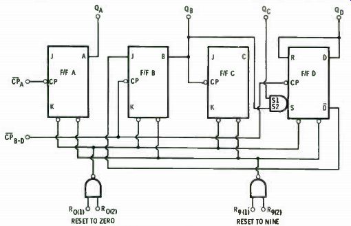
Fig. 6-8. Block diagram for a decade counter.
... to BCD 9 by putting is on the " Reset to 9" gate. Note from the Reset truth table ( Fig. 6-9B) that Reset-to-9 will take precedence over Reset-to-0. That is, if all four reset inputs are 1, the output will go to BCD 9.
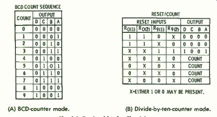
(A) BCD-counter mode. ( B) Divide-by-ten-counter mode.
Fig. 6-9. Truth tables for Fig. 6-8.
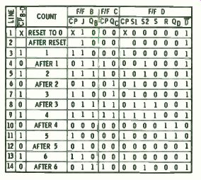
Fig. 6-10. Analysis table for divide by-five decade counter.
Operation of the divide-by-five ( or count to five) circuit is detailed in the analysis table, Fig. 6-10. Line 1 shows the status of the circuit after being reset to 0. Line 2 shows the circuit after reset and prior to any negative- going transition of the clock pulse. Line 3 shows the clock going high and line 4 is the status of the circuit after the first pulse goes to 0. When CPB-D goes to 0, flip-flop B, with input J = 1, is in the toggle mode and goes high (Q B = 1). Flip-flop C is in the toggle mode and toggles every time flip-flop B goes to 0. Flip-flop D is controlled by gate S and will go to 1 (on a negative-clock transition) whenever S = 1. This transition occurs on line 10 as the fourth count goes low. This, in turn, puts a 0 on input J of flip-flop B and inhibits B from toggling on the next pulse.
Output waveforms Q 11, Q C, and Q D are shown in Fig. 6-11.
The waveform for flip-flop A is not shown, but A is in the toggle mode and Q A will be a square wave if its input clock is a constant-frequency pulse train.
The circuit can operate in two ways. If output Q A is connected to input t1 5 ,77, and the incoming count is applied to in put A, the circuit will count from 0 to 9 and give a BCD output as shown in the BCD truth table ( Fig. 6-9A).

Fig. 6-11. Waveforms for Fig. 6-8.
For frequency division, a square-wave output (a wave with 50% duty cycle or high half the time and low half the time) is usually desired. In this case, the input frequency to be divided if applied at input CPD. D, and output Q D is used to drive input M. Output Q A is then a square wave at 0.1 the frequency of the input.
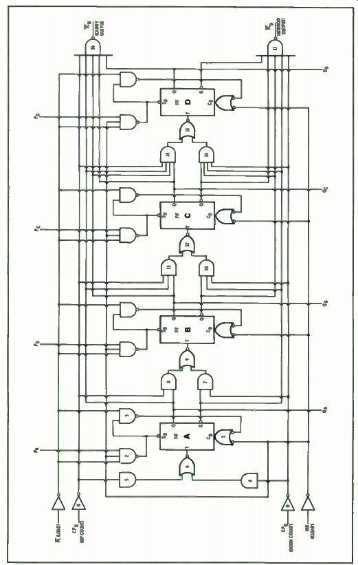
Fig. 6-12. Up/down binary counter.
UP/DOWN BINARY COUNTER
Counting up from 0 is similar to addition, adding 1 for each input pulse. Counting down is equivalent to subtracting one count for each pulse. The synchronous 4-bit binary counter shown in Fig. 6-12 is circuit type 54193/74193. It will count up or down, depending on whether the count pulse is applied to a count-up circuit or a count-down circuit. It can be set to 0000 using the Master Reset (MR) input and can be preset to any number from 0000 to 1111 by use of the Parallel Load (PL) input.
Consider first the reset function. When MR goes high, it puts Os on the four NOR gates ( which have active low inputs), and these in turn go high (to 1), which drives the four flip-flops to the Q = 0 state. The 0 input (from MR = 1) also acts to inhibit the AND gates of the parallel load circuit and prevents incorrect reset. Thus, for flip-flop A, Gate 2 is a 1; Gate 3 can be a 0 or a 1 without affecting reset. MR overrides the other functions, as indicated in Fig. 6-13.
The Preset function operates similarly to the MR function.
With MR = 0 and PL = 0, Gate 2 has two is and PA as the in puts. If PA = 1, Gate 2 is satisfied and goes to 0; QA goes to 1.
If PA = 0, Gate 2 will be a 1; Gate 3 then has two 1 inputs and goes to 0. This drives Gate 1 to 0, and output Q A goes to 0. The circuitry for flip-flops B, C, and D operates the same as flip flop A. The counter is quiescent when MR = 0 and PE = CPU = CP, = 1.
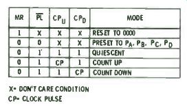
Fig. 6-13. Mode selection table for Fig. 6-12.
Circuit operation in the Count-Up mode is fairly complicated and is shown by the waveforms in Fig. 6-14. The starting condition for counting up is just after reset to 0000. The Down-Count input is held at 1, which makes Gate D = 0, set ting Gates 7, 10, and 13 to 0. Gate 4 is also a 0, which frees Gate 6 to follow Gate 5.
The Up-Count sequence is a series of positive-going pulses.
Assume input CP u is 0 immediately after reset. This drives Gate U to 1, which sets Gate 5 to a 1 and, in turn, Gate 6 to a 0. Flip-flop A will now toggle when Gate 6 makes a transition from 0 to 1.
As count pulses enter the CPU input, operation of the counter is shown by the waveforms in Fig. 6-14.
( To emphasize the operating sequence, the waveforms are shown with exaggerated rising and falling edges. The gate being driven does not begin to respond until the driving gate has completed its excursion.)
The sequence is as follows:
1. Input CPU goes to 1.
2. Gate U goes to 0.
3. Gate 5 goes to 0.
4. Gate 6 goes to 1.
5. Flip-flop A toggles and Q A goes to 1.
Nothing further will happen until the clock goes to 0.
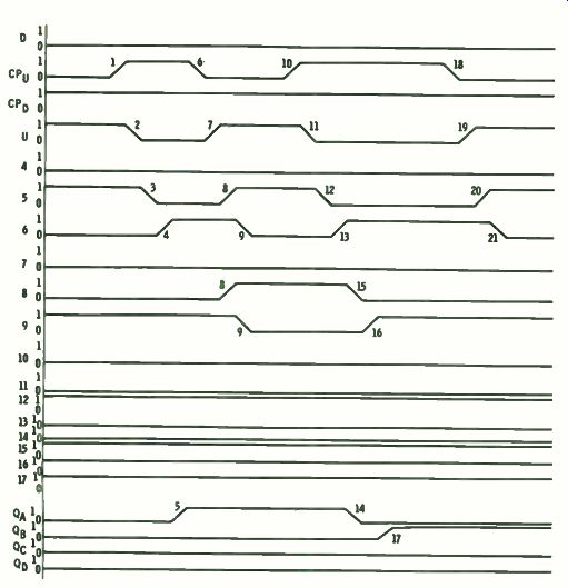
Fig. 6-14. Waveforms showing operational seq f gates in Fig. 6-12.
6. The clock goes to 0.
7. Gate U goes to 1.
8. The next two events happen simultaneously: A. Gate 5 goes to 1.
B. Gate 8 goes to 1.
9. Simultaneously: A. Gate 6 goes to 0. B. Gate 9 goes to 0. Nothing further will happen until the clock goes high.
10. CP, again goes to 1.
11. Gate U goes to 0.
12. Gate 5 goes to 0.
13. Gate 6 goes to 1.
14. Output Q goes to 0.
15. Gate 8 goes to 0.
16. Gate 9 goes to 1.
17. Flip-flop B toggles and output QR goes to 1.
Nothing further happens until the clock goes to 0.
18. CPu goes to 0.
19. Gate U goes to 1.
20. Gate 5 goes to 1.
21. Gate 6 goes to 0. Nothing further happens until the clock goes high.
The analysis can be continued in this manner and, the wave forms will show that the circuit operates per the truth table for counting up ( Fig. 6-15) .
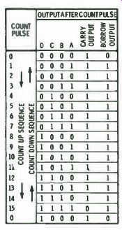
Fig. 6-15. Truth table for Fig. 6-12.
From Fig. 6-13, we see that, for Count-Down operation, CPL' is always 1, Gate U = 0 and Gates 5, 8, 11, and 14 are always 0. Therefore, Gates 9, 12, and 15 will act as inverters and will follow, respectively, Gates 7, 10, and 13. When input CPD goes to 0 after reset, Gate D goes to 1. Gate 4 goes to 1, driving Gate 6 to a 0, which prepares flip-flop A to toggle ( when Gate 6 goes from 0 to 1). Gate 7 has two inputs of 1 ( Q = 1 and D = 1) , so Gate 9 is driven to 0; thus flip-flop B is prepared to toggle when Gate 9 goes from a 0 to a 1. Flip-flops C and D are similarly prepared.
When input CPD goes to 1, Gate D goes to 0, making Gate 4 go to 0, and causing Gate 6 to go to 1; flip-flop A toggles. At the same time, Gate 7 goes to 0, causing Gate 9 to go to a 1, and flip-flop B toggles. Similar action takes place at flip-flops C and D. When input CPD again goes to 0, Gate D goes to 1. Gate 4 goes to a 1, again driving Gate 6 to a 0. When CPD goes to 1, flip-flop A toggles, but Gates 7, 10, and 13 inhibit flip-flops B, C, and D, respectively. As a result, the circuit follows the Count Down sequence shown in the truth table in Fig. 6-15.
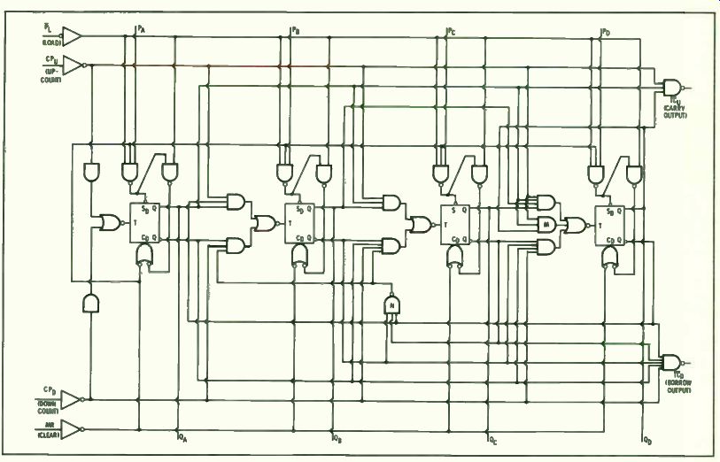
Fig. 6-16. Up/down BCD decade counter.
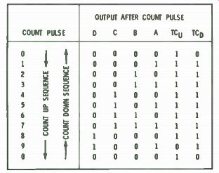
Fig. 6-17. Truth table for Fig. 6-16.
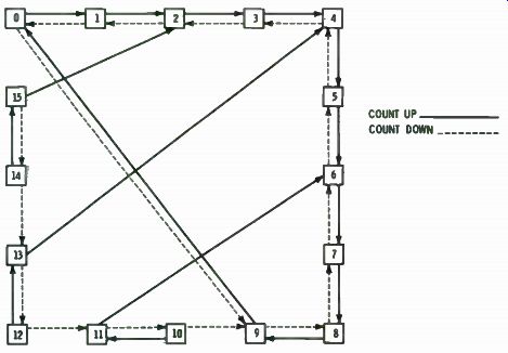
Fig. 6-18. State diagram of count sequence for Fig. 6-16.
The Carry Output goes to 0 when the counter is full and the next count-up pulse occurs. Similarly, the Borrow Output goes to 0 when the counter is empty and the next down-count pulse occurs.
UP/DOWN DECADE COUNTER
A synchronous up/down BCD decade counter, similar to the up/down binary counter, is type 54192/74192 shown in Fig. 6-16. Circuit operation is the same as for the binary counter, except that the count sequence is forced back to the 0000 state on the tenth count. This is accomplished through the actions of additional Gates N and M.
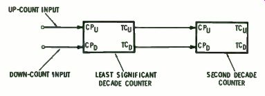
Fig. 6-19. Decade counters in tandem operation.
The counter can be preset to any count through the action of its parallel load circuit. Note that the counter can be preset to states that are not part of its regular count sequence. If, for example, the counter is preset to 1111, how will it respond on the next count pulse? The sequence of events is shown in Fig. 6-18 for all "out-of-normal-count" preloads. With the counter preset to 1111 ( decimal 15) , the next up-count will drive it to 0010 (decimal 2) , from which point it will proceed through the normal decade count. If the counter is preloaded to 12, the next up-count will drive it to 13, while a down-count would drive it to 11. Two up-counts in succession will drive the circuit into the main sequence at state 4.
By operating two decade counters in tandem, as shown in Fig. 6-19, the count capacity can be increased to 100. The Carry Output signal of the first counter is used as the input to the Up Count clock of the second counter. The Borrow Output signal is used as the Down-Count clock. More decades can be added in the same way. The binary counters shown in Fig. 6-12 can be operated in tandem in the same manner.
Prev: Link | --Link | --Link | --SHIFT REGISTERS
Next: ARITHMETIC CIRCUITS
Guide Index : Transistor-Transistor Logic (early 1970s)