Fig. 2-1. Measurement of speaker impedance.
| Home | Audio mag. | Stereo Review mag. | High Fidelity mag. | AE/AA mag. |
2-1. To Measure the Impedance of a Speaker
Equipment: Audio oscillator, resistor.
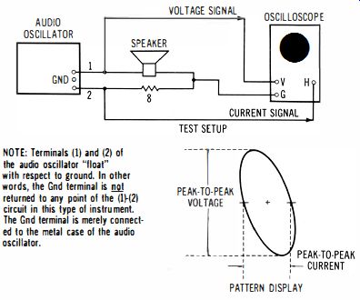
Connections Required: With reference to Fig. 2-1 , the speaker and resistor are connected in series across the push-pull output terminals of the audio oscillator. The voltage across the speaker is fed to the scope's vertical channel, and the voltage across the resistor is fed to the scope's horizontal channel.
Procedure: Use a suitable value of resistance (such as 8 ohms) to obtain a Lissajous figure of convenient size. Observe the value of the maximum vertical deflection and the value of the maximum horizontal deflect ion on the calibrated screen.
Evaluation of Results: The amount of vertical deflection indicates the peak-to-peak voltage applied across the speaker, and the amount of horizontal deflection indicates the peak-to-peak current flowing through the speaker. The impedance of the speaker is equal to the number of volts divided by the number of amperes. For example, if there are 2 volts dropped across the resistor, there is 1/4 ampere flowing; and if there are 4 volts dropped across the speaker, the impedance of the speaker is 16 ohms.
NOTE 2-1
Speaker Impedance Versus Frequency
The impedance of a speaker changes when the frequency of test is changed. Speaker impedance is customarily measured at 1 kHz. As the test frequency is increased, the impedance value ordinarily increases due to the fact that the voice coil is inductive, and inductive reactance increases with frequency. The phase angle between voltage and current may be measured as explained in 1- 3. This phase angle also varies with changes in the test frequency. At one or more test frequencies, it will be observed that the speaker is purely resistive (pattern is a straight diagonal line). When the speaker impedance becomes purely resistive, the reactance of the voice coil is being cancelled by the mechanical reactance of the vibrating cone assembly.
--------------
NOTE:
Terminals (1) and (2) of the audio oscillator "float" SPEAKER with respect to ground. In other words, the Gnd terminal is not returned to any point of the (1-2) circuit in this type of instrument. The Gnd terminal is merely connected to the metal case of the audio oscillator.
VOLTAGE SIGNAL OSCILLOSCOPE
PEAK-TO-PEAK
PATTERN DISPLAY
Fig. 2-1. Measurement of speaker impedance.
----------
2-2. To Measure the Input Impedance of a Transformer
Equipment: Audio oscillator, resistor, normal load for transformer (such as a speaker). Connections Required: Same as in Fig. 2-1 . Audio oscillator drives the primary of the transformer under test, with the speaker connected to the secondary of the transformer. (See Fig. 2-2.) Procedure: Same as in 2-1 . Evaluation of Results: Same as in 2-1 .
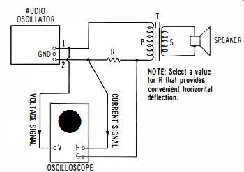
Fig. 2-2. Measurement of input impedance of a transformer.
NOTE 2-2 Transformer Turns Ratio, Voltage Ratio, Current Ratio, and Impedance Ratio The turns ratio of a transformer is measured on open circuit (no load connected to the secondary) . An ac voltage is applied to the primary; in turn, the ratio of primary voltage to secondary voltage is equal to the turns ratio of the transformer. Observe that the primary power (V" I,,) is equal to the secondary power (V.I,). Thus, a step-down transformer with a 10-to-1 ratio, for example, will have a secondary voltage equal to 1/ 10 of the primary voltage, and will have a secondary current equal to 10 times the primary current. As the secondary current demand is increased, the primary current drain also increases. The primary will draw a very small current when the secondary is open-circuited; this small current demand results from the facts that the primary reactance is not infinite, that the primary winding has resistance (12R loss), and that the core of the transformer has a small power loss in its magnetic circuit.
Note also that the primary/secondary impedance ratio of a transformer is equal to the square of its turns ratio. For example, a 10-to-1 transformer will have a primary /secondary impedance ratio of 100-to-1 . Thus, if an 8-ohm speaker is connected to the secondary, the primary input impedance will be 800 ohms. Or, if a 4-ohm speaker is connected to the secondary, the primary input impedance will be 400 ohms.
2-3. To Measure the Output Impedance of a Transformer
Equipment: Audio oscillator and two resistors.
Connections Required: Connect the test setup as shown in Fig. 2-3.
Procedure: Same as in 2-2.
Evaluation of Results: Same as in 2-2.
Value
NOTE: Rs has a equal to the source impedance of the intended
(Usually the output transistor driver. impedance of a amplifier).
OSCILLOSCOPE
NOTE: R has any value that provides ample horizontal deflection on the scope screen.
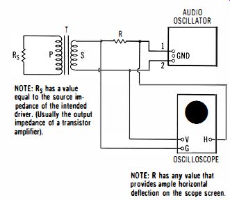
Fig. 2-3. Measurement of output impedance of a transformer.
NOTE
2-3: Output Impedance and Maximum Power Transfer
The output impedance of a transformer for coupling an amplifier to a speaker is of importance because maximum power is transferred when the source impedance matches the load impedance. For example, suppose that the source (amplifier output) impedance is 1600 ohms, and that the speaker impedance is 16 ohms. Then, maximum power will be transferred to the speaker with a 10-to-1 output transformer. In other words, the impedance ratio of a 10-to-1 transformer is 100 to 1, so that a 1600 ohm source will be transformed into 16 ohms (which matches a 16-ohm speaker) . In practice, output transformers are less than ideal-for example, an output transformer introduces phase shift in its low-frequency and high-frequency cutoff regions.
2-4. To Measure the Input Impedance Characteristic of a Crossover Network
Equipment: Audio oscillator, and resistor.
Connections Required: Refer to the diagram in Fig. 2-4; connections are the same as in 2-1 except that a tweeter speaker with a crossover capacitor C is included in the system.
Procedure: Vary audio-oscillator frequency through the range from 20 Hz to 20 kHz, and observe the extent of change in impedance pattern on the scope screen.
Evaluation of Results: When the value of the crossover capacitor C is optimum, a minimum change occurs in the impedance value as the test frequency is varied through the audio frequency range.
RESISTIVE LEVEL CONTROL MAY BE INCLUDED IN SERIES WITH THE TWEETER. AUDIO OSCILLATOR GND 0 TWEETER WOOFER
NOTE: A tweeter level control affects the impedance characteristic of the crossover circuit. A cone-type tweeter may employ a 50 ohm 2-watt level control; a horn-type tweeter may use a 150-0hm 2-watt level control.
OSCILLOSCOPE
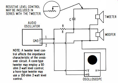
Fig. 2-4. Measurement of input impedance of a crossover network.
AUDIO OSCILLATOR
OSCILLOSCOPE TWEETER LEVEL CONTROL (IF USED)
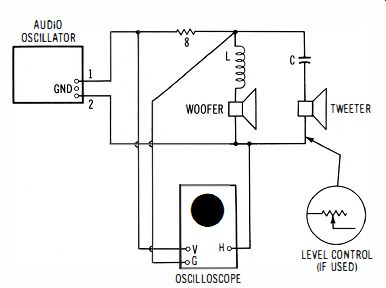
Fig. 2-5. Measurement 0' input impedance characteristic of an LC crossover
network.
NOTE
2-4 Crossover Circuit Operation
The simplest crossover circuit (which is sometimes adequate) is depicted in Fig. 2-4. A tweeter is connected in series with a crossover capacitor C, and the series arrangement is driven in parallel with the woofer. It is apparent that at some frequency, the reactance of the crossover capacitor will be equal to the tweeter impedance. This is called the crossover frequency. The crossover frequency depends on the value of the crossover capacitor. As an illustration, suppose that a 4-uF capacitor is used in series with an 8-ohm tweeter. Then, the crossover frequency will be 5 kHz, approximately. Or, if an 8-uF capacitor is used, the crossover frequency will be 2.5 kHz, approximately. At this crossover frequency, the tweeter consumes one-half of the power that it would consume with the crossover capacitor short-circuited. The crossover capacitor attenuates low audio frequencies, thereby preventing possible overload and damage to the tweeter. Although high audio frequencies enter the woofer, the overload potential is not as great. Note that better crossover network characteristics can be obtained by including an inductor in series with the woofer (see 2-5). 2-5. To Measure the Input Impedance Characteristic of an LC Crossover Network
Equipment: Same as in 2-4.
Connections Required: Connect the equipment to display an impedance pattern, as shown in Fig. 2-5.
Procedure: Same as in 2-4.
Evaluation of Results: When the values of the crossover capacitor C and the crossover inductor L are optimum, a minimum change occurs in the impedance value as the test frequency is varied through the audio-frequency range.
NOTE 2-5
Impedance Relations of an LC Crossover Network
An inductor has opposite reactance with respect to a capacitor. That is, as the frequency increases, inductive reactance increases. A crossover inductor may have a value of 0.25 mH; in turn, it will have an impedance of 8 ohms at 5 kHz (crossover frequency). Or, if the crossover inductor has a value of 0.5 mH, it will have an impedance of 8 ohms at 2.5 kHz (crossover frequency). Observe that when 8-ohm speakers are used in the arrangement of Fig. 2-5, the net impedance is not 4 ohms, because the crossover inductor L and the crossover capacitor C have different impedances at various frequencies. In normal operation, with correct values of Land C, the input impedance characteristic is practically constant at 8 ohms over the audio-frequency range. At the crossover frequency, the inductor has an impedance of 8 ohms, and the capacitor has an impedance of 8 ohms; the network input impedance is 8 ohms. At 0.1 of the crossover frequency, the inductor has an impedance of 0.8 ohm, and the capacitor has an impedance of 80 ohms; the network input impedance is practically 8 ohms. At 10 times the crossover frequency, the inductor has an impedance of 80 ohms, and the capacitor has an impedance of 0.8 ohm; again, the network input impedance is practically 8 ohms.
2-6. To Measure the Inductance of a Crossover Coil
Equipment: Same as in 2-1 .
Connections Required: Same as in Fig. 2-1 (crossover coil is connected in place of the speaker). Procedure: Use a value for the resistor that provides convenient horizontal deflection. Set the audio oscillator precisely to a suitable test frequency, such as 1 kHz. Observe the current value (resistive voltage drop), and the inductive voltage drop, as shown in the diagram of Fig. 2-6.
Evaluation of Results: The inductance of the coil is equal to the rms inductive voltage drop, divided by the rms current, and divided finally by 2 pi f, where f is the test frequency. The rms voltage is equal to 0.707 times the peak voltage. Pi is equal to 3.14.
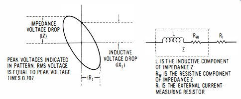
Fig. 2-6. Voltage indications in a Lissajous figure for a coil.
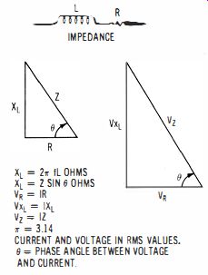
Fig. 2-7. Relations of resistance, inductance, and phase angle in coil in
response to ac.
NOTE 2-6
Inductance, Resistance, Reactance, and Impedance
When working with inductive impedance (R and L in series), it is helpful to observe the relations of L, R, XL, Z, VR, Vx .. , and Vz, as shown in Fig. 2-7. When an ac voltage is applied across R and L in series, the resistor drops IR volts, the inductor drops IXL volts, and the impedance drops IZ volts. Thus, a coil that has an inductance of 0.5 mH will have an inductive reactance of 3.14 ohms at 1 kHz. Its impedance depends upon its winding resistance, as depicted in the diagram. Observe that the peak IXL voltage drop is given in the Lissajous figure as shown in Fig. 2-6. The rms value of the IXL voltage is equal to 0.707 times the peak IXL voltage.