A Dynamic Range and Clipping Indicator-- What's really going into your power amp's input?
by DAVID M. WHITE, JR.
THIS ARTICLE IS A RESULT of listening to sonic aberrations in my stereo system.
I could hear my system break up, but I had no way of telling whether the problem originated in the amplifiers or the speakers. I thought of solving the problem through a device with a LED readout; but after reviewing TAA back issues, technical books, and commercial items, and consulting friends, I realized that what was available was either limited in dynamic range, or overly complicated, or both.
Another problem was that most devices measured the amplifier's output, which I could not do as I direct couple class A tube amplifiers to my mid-range and tweeter panels. So what started out as a simple clipping indicator quickly became a dynamic range indicator as well. Watching the fantastic dynamic range of some of the direct discs is a very illuminating experience (no pun intended)--I have observed over 60dB. I have also watched the 6-10 dB maximum range of some rock stations.
I am also amazed at how much of the time amplifiers in a multi-amp system can be noticeably clipped while reproducing wide dynamic range material. A friend once calculated it would take 8500 watts to drive AR-3As to live symphonic levels in a living room.
WHAT DO WE WANT?
Let's define the perfect dynamic range and clipping indicators: It: 1. has flat frequency response from 20Hz to 20kHz; 2. can detect both positive and negative wave-form clipping; 3. has fast attack and slow decay; 4. can display a single half cycle of clipping at 20kHz; 5. can easily be adjusted for various amplifier sensitivities from .5VRMS to 2.25VRMS for 0-dB; 6. has dynamic range of -100dB to +20dB; 7. is thermally stable; 8. is easy to build, adjust, and set up, and uses readily available parts.
How well have I succeeded?
( a) frequency response measured on a continuous sine wave referenced to 1kHz is 0-dB at 20Hz, -0.5dB at 20kHz, and only 1.7dB down at 100kHz.
( b) There are several reasons for the extremely wide bandwidth. The - 3dB low frequency rolloff at .16Hz will immediately reveal any rumble in the turn-table/arm/cartridge combination. The high frequency response will show any tape recorder oscillations or CD-4 carrier leakage.
The high speed precision rectifier allows display of both positive and negative peaks.
( c) I designed the unit to have a - 60dB to 0 dB turn-on time of 22u S and a decay time of 300mS. I chose 22uS attack time to allow display of . 5Hz at 20kHz, while the 60dB decay time of 300mS allows the readout to decay slightly faster than the reverberation time of a living room or a studio.
( d) Potentiometer P1 allows easy adjustment of the input sensitivity. All you need to set up the circuit are an audio oscillator and a sensitive VTVM.
( e) Thermally the unit is fairly stable; it settles to normal operating conditions in about 30 seconds.
( f) The unit is straight-forward and easy to build. Only a few parts are not readily available, although I have specified many 1% resistors. The LM334 is the only part you may find difficult to obtain.
( g) Only in the dynamic range did I have to make serious compromises: I had to cut the -100dB range to - 60dB. Even - 60dB is pushing things as it is 1mV AC RMS referenced to 1 volt at 0 dB. -100dB is 10uV, much lower than the 50uV noise output of most preamps. If you have had the opportunity to make very low level measurements, you know the difficulties you can run into: leads have to be shielded, hum is a constant problem, and the noise is not weighted. I waived the + 20dB be cause few preamps, crossovers, etc., can put out over 10VRMS and I would have required a power supply of more than ± 15VDC. In any case, the remaining 70dB range will more than tax your stereo system.
HOW TO DO IT
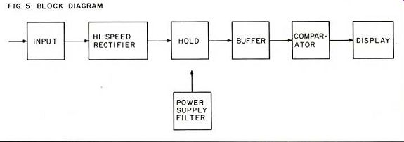
For an outline of the indicator's design and operation, refer to the block diagram in Fig. 5. The input block consists of C2 which prevents DC voltage from causing false readings, while R33 provides the 100k input impedance to avoid loading down the source.
The high speed rectifier consists of IC1 and IC2 . The precision rectifier allows us to measure both positive and negative peaks. I chose the LM301s for their high output current of 25mA. Resistors R27 and R28 are in the circuit for stability and to give the holding circuit an RC charging time of 22uS ( T= 0.22uFx 10x 100); I picked 22u S because a 20kHz sine wave has a half-cycle time of 25uS. The current required is:
-----Fig 5
dv __ dt c dvxc dt dv is 1.5VRMS reading) 2. 12V 2.lZx .22x 10_a x 1.414 peak
=i=2lmA 22iiS
The holding circuit consists of capacitor C1, C and zener diode D C is discharged by constant current source IC a National Semiconductor current source adjustable by one resistor from 1 to 10 mA. It can also be compensated for thermal stability, but we don't need to do that for this unit. Because the LM334 has to have a 1.5 volt differential across its terminals, I added the zener diode to provide -3V so the current sink will go below 0 volts.
You may be wondering why I made things so elaborate. Well, we could replace the whole set of parts with a resistor, but this causes one problem: the discharge through a resistor is not linear. In some cases it would take five minutes to discharge the capacitor.
I picked 300mS as the display decay time from 0dB to - 60dB because the reverberation of most living rooms and studios is more than that. Given that a 0dB, 1.5VRMS signal has peak voltage of 2.12 VDC, we can use the same equation to determine the - 60dB decay time:
dv/dt = i/c
Therefore a discharge the Current values R=
.22x10'
= 1.5, 1.5
current will capacitor in 330mS. Current values are determined by:
R_34= 43.2k
A quick note: a 1mS flash is visible. With our constant current source we will have a voltage drop of 7mV in 1mS or less than 0.03dB at 0dB.
Each of the 12 voltage comparators has varying input leakage current of Z5 to 300 uA. To calculate the current sink value we need the buffer block, IC to isolate the current sink from the voltage comparator. Pot P adjusts 1C offset voltage. I chose resistors R and R so the input leakage current would not trigger the -60dB LED. Those of you who have experience with LM339s will know of their tendency to oscillate at turn-on. Capacitor C bypasses them to ground.
The comparator block consists of three LM339s (ICs 4-6); these quad voltage comparators will handle 20 mA of current continuously at a price which won't wreck your budget. If you decide not to use all the LEDs be sure to ground the comparators unused inputs and outputs, to avoid oscillations in the LM339s.
I chose readily available voltage divider values which allow enough current through the divider so the LM339 leakage currents will not affect the values. Pot P allows you to adjust the unit easily for varying amplifier sensitivities. The turn-on points are - 60dB, - 50dB - 40dB,
-30dB - - -6dB
-3dB, 0dB, +3dB, +6dB, and
+ 10dB.
In practice the LEDs for the first four points are on most of the time,
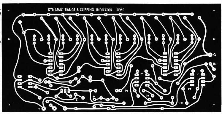
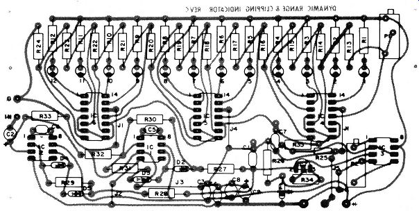
Fig. 3, Above, stuffing guide for the circuit board.
Fig. 2. Top, full sized negative of the etched circuit card the indicator.
-------
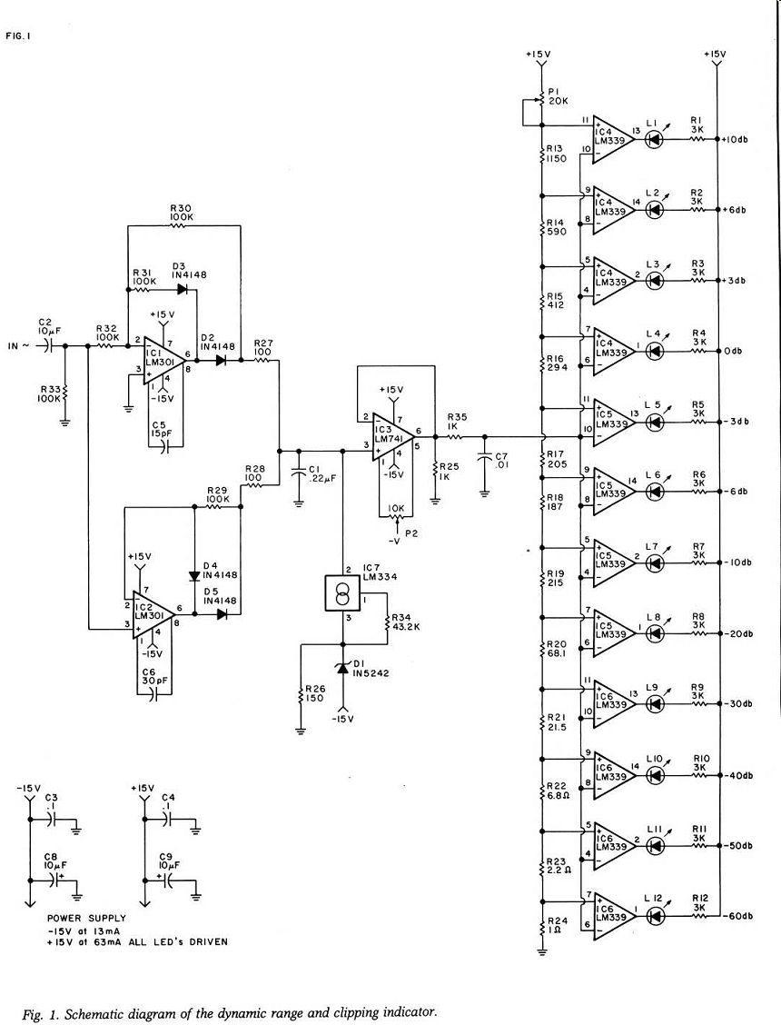
Fig. 1
... but they also allow you to measure surface noise on records and tape hiss. The - 6dB and - 3dB LEDs tell you when you are close to clipping.
The + 3and + 6dB levels are valuable to tape recordists, while the + 10dB level is useful for measuring output and distortion ahead of the power amps. If you decide to change the voltage divider values be sure to take leakage currents and turn-on points into consideration.
The display block consists of the 12 LEDs and their current limiting resistors, R1 - 12 . I set their value at 3k to minimize current requirements.
Six boards monitor the inputs to my six amplifier channels. If I were using 20mA in each I would need a 1.5 amp supply.
A 3k resistor will allow 4.3mA of current through the LED, as the LED has a forward voltage drop of about 2V. Do not use a resistor of less than 650Ohm for current limiting. Increasing the current in the LED only seems to increase the brightness off-axis. I chose green LEDs for -60dB to -6dB, yellow for -3dB, and red for 0dB to -10-dB.
The power supply block consists of capacitors C3 , 4 , 8 , and 9 . C3 and C4 are 0.1uF disc for high frequency bypass while C8 and C9 are high quality tantalums to eliminate the LM339 turn on oscillations which make IC3 to run rail to rail and cause a 1MHz power supply oscillation.
ASSEMBLY AND SET UP
Assembling the unit is straight forward. Refer to Fig. 4 for component layout, pinouts, and orientations. I laid out the board so you can use 1 /4 or 1 /2 watt resistors in most places and .3" or .4" capacitors. If you wish, you can, use vector board to space your LEDs out from the board and use the same holes to mount the unit to a front panel (see Fig. 00). The board also has mounting holes top and bottom to allow LED orientation in either direction into a panel. The board is single-sided to keep costs down and yet maintain simplicity and performance.
Maximum power supply requirements are 13mA @ -15VDC and 63mA @ + 15VDC. I strongly recommend using a separate supply for this indicator to avoid signal supply modulation. Please note the current requirements are for one channel only. The power supply in the Jung White PAT-5 modification is excellent for this use (see TAA 1/78, p. 7). Whatever you use, it should be fairly well regulated.
Set up and adjust are also simple and straight-forward. Connect an AC signal generator to the input terminals, set it to 1kHz, connect a sensitive AC VTVM and adjust the signal generator to the 0-dB input of your power amplifier. Most power amps need 1.5VRMS to drive them to full output, although some go as low as 0.75VRMS and as high as 2.25VRMS.
Turn pot P1 in the correct direction until the 0-dB LED stops flickering (i.e., just barely on). You will see flashes as the noise reaches the 0-dB point. You'll be surprised how much of the time you clip.
Reset the signal generator to -60dB (i.e., 0-dB level divided by 1000). This is the critical and difficult part of the adjustment. Adjust Pot P2 until the -60dB LED goes out. Change directions, turning the pot until the -60dB LED flickers on.
On one of the nine boards I built, one of the 301s had such high output voltage (due to offset bias) I could not null it out. Replacing the 301 cured this problem. On another board the - 60, - 50, and - 40dB LEDs all used to light up at the same time: swapping 339s cured this problem, and I added several bypass capacitors so you should have no trouble. I mention it, however, to prevent some poor reader from pulling out his hair trying to correct it. Repeat the adjustments to tweak the board into perfect adjustment.
CAVEATS AND COMMENTS
A few caveats about using the unit. If ...
-----------
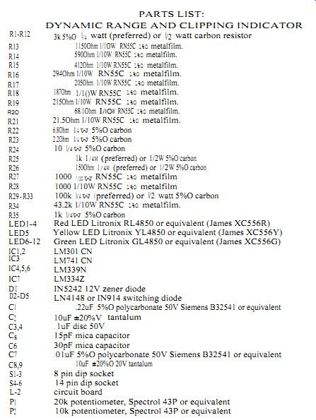
PARTS LIST:
DYNAMIC RANGE AND CLIPPING INDICATOR
------------------------------
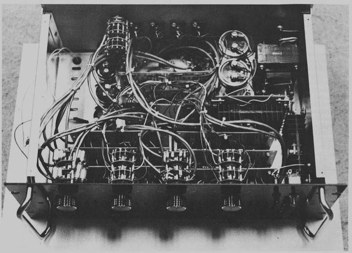
Fig. 6. Inside view of the author's unit which combines two three-way electronic crossovers with ±6dB adjustable gain adapted from Walt Jung's versatile 30Hz filter (TAA, 4/75, p. 14), and modified Old Colony crossovers, a Jung ±15V power supply (TAA, 4/74, p. 14), a PAT 51WJ-IA power supply (TAA, 3, 79, p. 24), and six dynamic range/clipping indicators. The six monitor the outputs of the two three-way crossovers. The Jung power supply feeds the six indicator circuits while the PAT-5/WJ-1A supply powers the crossovers and a pair of30Hz high pass filters.
... your preamp does not have a sub sonic rumble filter be sure to use one; otherwise you will measure the warp output of your cartridge-arm combination instead of the dynamic range of your records. The Jung 30Hz filter ( TAA 4/75, p. 14) is excellent. An easy way to determine whether you need a filter is to look at the output of a warped record between cuts.
The extended high frequency response will allow you to measure CD-4 carrier leakage and tape recorder bias leakage during rewind if you have these components in your system. This readout should also show if your system is oscillating anywhere.
If you use "surplus" LED's from other than the listed sources you may get a great variation in brightness. In such a case, it may be necessary to ...
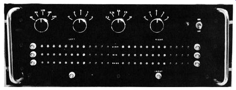
Fig. 7. Front panel view of White's crossover/range and clipping indicator.
The top switches control crossover frequencies and ±3 or ±6dB gain of
the crossovers.
... limiting resistor. Also you may want to swap the LM339's in the IC6 position. Due to internal cross coupling the first three LED's may turn on at the same time. During development of the circuit I noted this phenomenon, which seemed to be unit variation rather than batch problems.
A last correction is the calculation of the decay time. The 22uF capacitor C1, is effectively shunted by 60.31 until the switching diodes shut off at 0.7VDC at which time the shunt ...

Fig. 8A; Fig. 8b
... resistance increases to 231k. The current source keeps the -60dB LED shutoff at a reasonable time.
HOW TO USE IT
A few comments on uses for the readout other than as a peak reading meter in your system. A pair is light and portable for tape recordists' on location use to set record levels or measure ambient room noise. If you make R34 switchable and use two readouts (one fixed and one switch able) you can measure reverberation time (approximately) by matching the readouts' - 60dB decay times.
In the eight months that I have been using my readouts I have learn ed quite a bit about my system.
Record surface noise is clearly measurable, as are the outputs of ticks, pops, and scratches on records.
The phono preamp and cartridge output noise are clearly measurable with gain full up. You can also measure the hum going into the amp if that is the predominant noise in your system.
The dynamic range of various types of music and/or FM radio stations becomes evident. Some sources (FM rock stations) have only 3-6dB dynamic range, while one of the Boston PBS stations strains my tuner's abilities. On direct disc the peak-to-average readings will vary with the type of music and the way recordings are miked. On jazz records, e.g., Sheffield's Lab 3 The King James Version, some of the peaks are 30dB higher than the average level; the same company's classical direct disc recording of Prokofiev's Romeo and Juliet has mainly 10dB peak-to-average levels.
I think you will find the dynamic range and clipping indicator a very worthwhile and informative addition to your system.
----
Also see:
A Family of Power Amplifier Power Supplies -- A versatile circuit for regulated DC in quantity, by James E. Boak
A High Accuracy Inverse RIAA Network -- New light and hardware for the phono curve's basic shape, by Stanley P. Lipshitz and Walt Jung