IMPROVING THE CDB-650's DAC
---ABOUT THE AUTHOR: John Allgaier lives in Kalamazoo, Michigan with his wife and three children. His current passion is pursuing sonic heaven via tube electronics. ---
SINCE I PURCHASED a Magnavox CDB-650 16-bit player, I have made the upgrade modifications I proposed for the 14-bit players and a few new ones.
Areas of concern included DAC, analog section, clock jitter, grounding, and power supply.
TDA1541A DAC Remembering the "Debacle of the DAC" capacitor mods to the TDA1540 DACs, I wished to make this one cleaner and easier. I included provisions for zeroing the output of the I/V amp stage on this board for those who chose not to use a piggyback board from my previous articles (TAA 4/88, p. 19 and 4/89, p. 8). I also added + 5V regulators to isolate the DACs from the digital supplies.
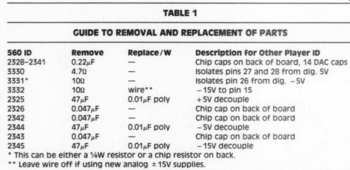
Everything is straightforward. Capacitor locations are provided for 1uF, 0.1uF, and 0.01uF. You must take parts off of the main board; follow Table 1 for correct removal and replacement. Use a three-level wirewrap 28-pin socket with machined pins (available from Digi-Key) at the DAC position. Work very carefully when unsoldering the DAC and other parts; the board/traces use better quality material than the older players, but you are removing a 28-pin IC that you will reuse. You might need to “chase ” the 28 holes with a small drill bit to fit your socket. If you use new * 15V supplies, the board pro vides voltage points for connection.
Remove R3332 (all references are for the CDB-560), the 10 ohm resistor in series with the - 15V supply. Omit the Table 1 wire jumper. If you use the existing + 15V supplies, add the wire jumper and bring the players' + 15V supply to the board's + 15V supply point. If you use a piggyback #3 or #4 board (TAA 4/89), leave the 100 ohm resistors, 10k pots, and 330uF caps off the piggyback boards since these parts supply current to the DACs and are better located close to them.
Analog Section
In the analog section I did all the usual things: POOGE the resistors with metal film; LO-ESR caps; short out the power supply decoupling resistors 3352, 3353, 3358, and 3359; and so on. If you are using a new + 15V supply, pull these resistors and connect the supply on the amp side of where the resistors were.
Replace caps 2358, 2359, 2364, and 2365 (22nF) with 330uF LO-ESR types paralleled with 0.1uF polys. Remove the output coupling caps 2366 and 2367 and resistors 3360, 3361, 3362, and 3363.
Run a high-quality wire from IC 6306, pin 7 to the right-channel output connector and from IC6307, pin 7 to the left-channel output connector. Cut the traces leading from the output connectors right at the connectors to re move the mute circuit from the audio signal, eliminating another degrading source from the music. This is optional for retaining the mute capability.
POOGE the analog filter around the 'B' section of each op amp per Jung's POOGE-4 article (TAA 1/88, p. 7 and 2/88, p. 19: resistors, cap value change, and coil removal). The caps in the analog section of my player were small blue tubular ones with a “KP"' designation. These are Philips polypropylene types so leave them alone.
Now for one of the biggest MUSICAL improvements you can achieve-a new op amp from Analog Devices. Forget the NE5535. Forget the AD712. Even forget the NE530/Jung special with video buffer. The AD847AN single amp IC (AD827AN for dual) puts them all to shame. It produces resolution, dynamics, clarity, and detail as I have never before heard from CDs.
TABLE 1
GUIDE TO REMOVAL AND REPLACEMENT OF PARTS
Description for Other Player ID Chip caps on back of board, 14 DAC caps Isolates pins 27 and 28 from dig. 5V Isolates pin 26 from dig. -5V
-15V to pin 15
+5V decouple
Chip cap on back of board
-5V decouple
Chip cap on back of board
-15V decouple
* This can be either a ¥W resistor or a chip resistor on back.
** Leave wire off if using new analog = 15V supplies.
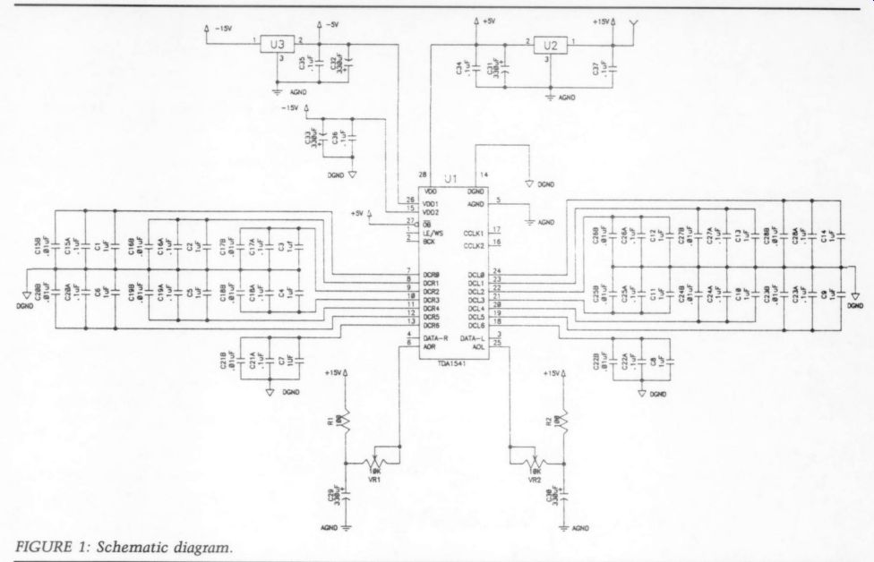
FIGURE 1: Schematic diagram.
--------------------
TABLE 2
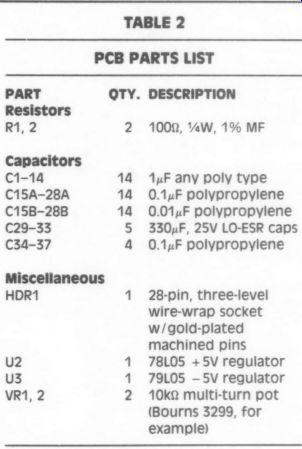
PCB PARTS LIST
PART | QTY. | DESCRIPTION
Resistors
R1, 2 2
100 ohm , 0.25 W, 1% MF
Capacitors
c1-14 C15A-28A C15B-28B
C29-33
C34-37
1uF any poly type
0.1uF polypropylene
0.01uF polypropylene
330uF, 25V LO-ESR caps
0.1uF polypropylene
Miscellaneous
HDR1
28-pin, three-level wire-wrap socket w/gold-plated machined pins
78L05 +5V regulator
79L05 -5V regulator
10k-ohm multi-turn pot (Bourns 3299, for example)
--------------------------
Complex musical passages of multi-instrument textures are resolved into individual voices easily followed. Sound staging is exceptional--left to right and depth. Bass dynamics are accurate and controlled. Acoustic drums are almost in the room. As the lower drums are played, you can hear the springs on the snare rattling.
Lest I seem to be raving, let me pause to wipe my chin and say friends in California and Connecticut have verified my findings without any prompting from me. You should try these amps.
I installed them after I did all the other mods. I used the AD847AN with the LM6321 video buffers on my piggyback #4 boards. This was more “in room' than the dual amps, though not by much. If you use the dual op amps, skip the piggyback boards with their servo amps if your preamp has capacitive coupling.
The audibility of servo amp circuits has been taking a lot of hits in purist circles. I believe the problem is using too short a time constant. In my piggyback circuits I was using a 1M ohm/ 1uF combination for a cutoff frequency of 0.9Hz. This first-order filter made with a high gain op amp will still influence the lowest frequencies of audio. A solid-state amp! have uses a cutoff of 0.04Hz. I have changed to a 1M-ohm/11 uF combo for a cutoff of 0.08Hz. The lowest registers are more tight and deeper as a result. It is highly recommended.
DAC Clocking Jitter
How well the bits for conversion arrive at the DAC and are moved through it determines the accuracy of conversion.
Lately this has become a major concern in high-end players (like yours now). In the TDA1541 DAC a provision for jitter free operation was provided, though not implemented. Early data sheets and application notes for the 1541A version stated this feature was deleted, but the August 1989 sheets continue to support it. Instead of the bits clocking them selves in, the system crystal does the clocking, producing more stability.
To implement this feature, cut the trace connecting pins 2 and 4 on the DAC, located on the back (non-component side) of the board. I used a piece of Belden Teflon coax to connect pin 9 (Xsys) of the SAA7220 digital (4x oversampling) filter chip to pin 4 (SCK) of the DAC. I grounded the shield at both ends--pins 12 and 13 of the 7220 and the fat trace next to pin 4 of the DAC (ohm it for continuity to be sure).
Looking further at the signal lines, I did not like the Xsys trace to the SAA7210 decoder chip. Cut and remove the trace from pin 19 (Xsys) on the 7210 decoder as far as you can. Be careful closer to the 7220 filter chip as there are added components not documented on the schematics to hold off the Xsys clock until the supplies stabilize, a system reset.
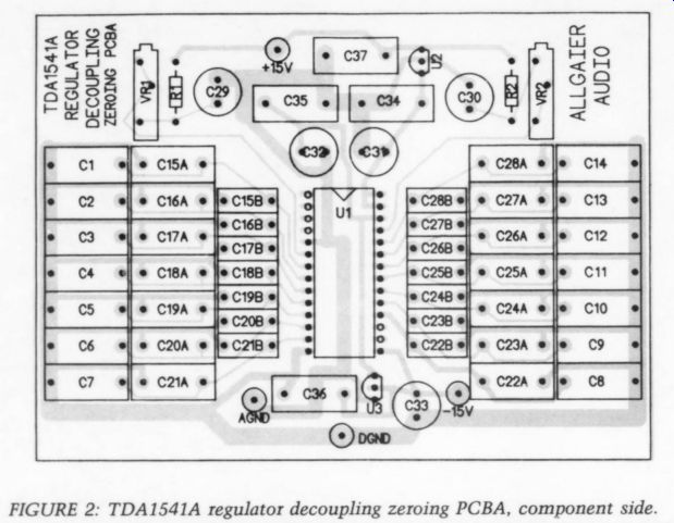
FIGURE 2: TDA1541A regulator decoupling zeroing PCBA, component side.
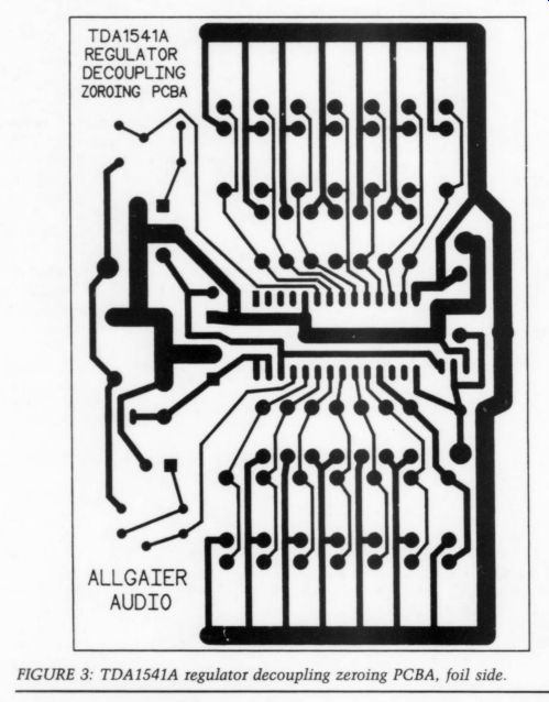
FIGURE 3: TDA1541A regulator decoupling zeroing PCBA, foil side.
When you come to a branching of the traces, stop. Again use coax to connect Xsys to pin 19 of the 7210, grounding the shield at pin 20. The other end goes to the 7220 pin 9 and is grounded at pins 12 and 13. Three other signals from the filter chip to the DAC are critical to accuracy of the conversion: the bit clock, word select, and left/right audio data signals. The traces between the filter and DAC pass through two wire jumpers on their journey to the DAC.
I lifted these traces off the board and ran individual, direct wires. I used three strands of separately insulated 30-gauge wirewrap wire for each signal to make the connections. What benefits are de rived from these mods? A certain gelling of the sound. A lowering of conversion noise. A more distinct accuracy in the transients and overall sound.
Improved Grounding
The more I examined the layout of the circuit board, the more amazed I was at the grounding scheme used on the PCBA. There is a total ground plane on the top side of the board, but the circuit ground is tied to the plane only in a few places. This did not appear to be a very low impedance ground scheme.
The ground scheme can be improved by soldering all ground connections of components, ICs, or jumpers (in the digital section, pre-DAC area only) to the ground plane. In the power supply section, locate the ground trace that has holes without components in them. Use a wire and tie these holes to the ground plane. I noticed improvements in a lowering of background noise and attendant clarity.
Power Supply Improvements
As a beginning, POOGE all the caps in the power supply area with LO-ESR types in values as large as is practical, observing voltage ratings. Be generous in the caps that filter any supply for the servo circuits. In the = 15V analog section, I used a separate twice-regulated servo-controlled power supply a la Borbely (improved Sulzer) as used in his low-noise pre-preamp project. I laid out the board to increase ground planes and keep the plus and minus supply grounds separate back to the center tap of the transformer.
I also reduced the size of the board and changed its voltages. To implement separate supplies for the analog section, you must remove the jumpers and resistors around the DAC and op amps to isolate them from the existing supplies. This assumes you used my DAC helper board, which you must connect to the new supplies. Also consider reducing the load on the existing supplies by un plugging the headphone amp boards if you do not use the phone output. You should do this anyway as it sonically loads the audio outputs.
In a CDB650, unplugging connector 48 on the main board removes the filter board and headphone board as a load on both the supplies and audio outputs.
You cannot physically remove the filter board unless you replace the regulator and associated parts that supply the FTD display. This circuitry is separate from the analog filter section, but uses board space on the filter board. I have been told leaving this display off reduces noise in the signal, but I have not tried it as I have no access to a CDB-650.
Conclusions
Once again, is all this worth it? I whole heartedly think so. It will make you re consider a separate digital decoder. It will make the large price for small gain a tough decision. It will make the effects of CD tweaks quite apparent. Greening the edges and center clear plastic area, washing off of the mold release oil using a plastic cleaner (Miller-Stephenson Cleaner For Plastic-Glass-Metal MS-260 203-743-4447 -quite an improvement in itself), and waxing the playing surface with a static-free wax (3M Imperial Hand Glaze available from body shop supply stores) are among these. All the usual cautions of voided warranties, careful circuit work, and undetermined long-term effects of tweaks to CDs apply.
Future areas to explore include stiffening the bottom chassis, internal damping all over the chassis, and a stiffening/dampening of the CD tray itself.
Any ideas or experience would be welcome information.
++++++++++++++++
Also see:
AN ACTIVE INVERSE RIAA CIRCUIT, By Dmitri Danyk and George Pilko
A SIMPLE CURVE TRACER--Part II, By Erno Borbely