INTRO; EDITORIAL; REVIEW; BOOK REVIEW; ASK TAA; AUDIO AIDS; CLASSIC CIRCUITRY, The Bell Model 2200B Hi-Fi Amp; JUST LOOKING; LETTERS
INTRO
Readers who own a Philips-based CDB-650 CD player will welcome John Allgaier's article. He has improved the player's DAC-among many other upgrades.
Next in the lineup, contributing Editor Erno Borbely introduces readers to balanced audio amplifiers. He discusses how to use the balanced topology in your equipment and provides many practical circuits.
Turn to Dmitri Danyk and George Pilko explain the procedure and offer a circuit to test a phono preamp stage with an active inverse RIAA circuit.
In his second offering this issue, Erno Borbely wraps up his curve tracer feature. He includes examples of curves from several devices.
Also in this issue (see below), Jan Didden reviews a circuit simulation shareware program, PC-ECAP. Turn to details for his evaluation.
EDITORIAL
Early Wisdom
An operator, using stereosonic reproducers for the first time, will almost certainly try to achieve perfect balance between channels. Indeed, he is exhorted to do so, more than one writer on the subject stating it is mandatory that the gain and tone controls be ganged for this very purpose. This, in common with the many other pontifical pronouncements by the engineering and hi-fi fraternity, is nonsense. To forestall righteous anger and condemnation, the author proposes to make a slight digression.
Engineers are, on occasion, apt to make definitive statements about subjective matters, without always considering all the available evidence. If this be not so, how can one account for the changing fashions in the 'hi-fi world'? Each new circuit is equated with the 'real thing,' and each subsequent one is so much better than the last; but it is also the 'real thing,' a sort of ultra-real realness.
"At one time, 10W was ample for the average living room; now, according to one concatenate authority admittedly not overmuch given to understatement, 100W is the figure. And we aren't really honest about it. We use coordinate geometry as proof of our statements and raise Fourier analysis to the dignity of a gospel; but a Fourier series merely happens to be a convenient tool in the manipulation of partial differentials, while, for statements about problems in which subjective perception is an important factor, tensors appear to be the appropriate discipline. Whichever way the matter is viewed, the figures are merely a manipulative convenience, and not statements of fact.
'The author is a very ordinary engineer, busily engaged in scratching a modest living in a competitive business; but he is, also, a professional musician of vast, literally, vast experience. This is not to say he is anything but a mediocrity, even in that profession, but his first public appearance was at the age of seven, and he is not going to say how long ago that was: (off the record, he would be a grandfather now if his children weren't so lazy!).
"On the strength of long acquaintance with hi-fi in the raw, his advice to the amateur using stereo for the first time is to give up listening with the slide-rule but use, instead, certain rather old-fashioned instruments, a couple of which can be found in most well-appointed homes.
They are known as ears, and their discrimination is remarkable--in fact, they are the standard by which all other instruments are, or should be, judged. If stereo sounds better with one channel slightly louder than the other, play it so. If the performer seems to be in the room, with treble up on track 1 and bass up on track 2, that's where the controls should be.
"If it sounds right, it is right, and don't let any long haired back room boys-including the author-tell you it's not. Your ears aren't perfectly matched, neither are the two halves of your room, nor your tastes with the next man's. All the controls are for use, not ornament."
Arthur W. Wayne wrote the heretical opinions I have reprinted above in the pages of Audio Engineering, precursor to Audio (and a quite different periodical), in November 1957. His article was a design for a tape record/play amplifier (based on the wonderful Ferrograph deck) and a delightful bass reflex speaker system to match. The article is included in Audio Anthology Four soon to be available as a reprint through our Old Colony division.
Mr. Wayne's views take us back behind all the conventions that have grown up in the audio business over the intervening 35 years. He combines, in one person, ideas that today are championed by opposing groups. Neither “side ” could accept both the views he holds. His experience as engineer and musician give him a perspective which is a healthy reminder.
His “concatenate authority not overmuch given to understatement ” is still with us. The Coca-Cola Company is not the only organization claiming its product to be
'the real thing." The prestigious Philips organization allowed its ad copywriters a few years ago to resort to an oxymoron to describe their newest CD player as 'more perfect." Notice that Mr. Wayne makes subjectivism the final arbiter-but not a universal one. This standard can serve only a very small population of one: yourself. Whether lengthy discussion between audiophiles can, in fact, find language to represent their experiences accurately to one another in comparisons that match is still a matter under question. We are fortunate to have, finally, the first codification of a proposed vocabulary from J. Gordon Holt.
My company is proud to have had the privilege of publishing The Audio Glossary. It may not achieve the status of Dr. Samuel Johnson's Dictionary or Noah Webster's, but it is the first consistent attempt to flesh out our small collection of terms for describing what we hear.
I am glad to see that attempts are being made to enhance our stock of objective information about how well equipment performs. The current issue (Feb. 1991) of Electronics World + Wireless World! carries Professor Ivor Brown's proposal for a new three-tone test of amplifier quality. We need more such proposals and rigorous testing of them. Subjective evaluations and technical measurements are not mutually exclusive standards.
-E.T.D.
Reed Business Publishing, 205 E. 42nd St., New York, NY 10117
REVIEWS
CIRCUIT SIMULATION
Reviewed by Jan Didden
TRADITIONALLY, CIRCUIT DESIGN has been not only a science but also an art. Amateurs and professionals alike start a circuit with a rough idea, calculate component values, and choose devices from data books. A prototype is built and tested. Seldom is it correct the first time.
So, the designer recalculates, makes changes, re-tests, substitutes devices, and continues this process until he has a working product.
Sometimes experienced designers get very close the first time and know that, say, a calculated resistor value must be increased by 20% to be right. This is the “art ” part. It gets more difficult if you must build 100 units of your design. For instance, you might be faced with spreads in transistor Hg from 100 to 500. The one in your prototype might be a 500Hg; unit. Will the circuit be within spec with a 100H; unit? Selecting transistors is expensive.
You would have to build several prototypes, with worst-case combinations, and make sure all meet the specifications. But finding the worst case combination for a particular spec can be a major project in itself. These problems were particularly important for the design of early integrated circuits, when engineers faced large spreads in IC production processes.
Therefore, it is no surprise that as early as the 1960s people began looking to computers to assist in the design process. The program that is the basis of almost all current circuit simulators was developed at the University of California at Berkeley and was called SPICE (simulation program with integrated circuit emphasis). This was a powerful R&D tool. An engineer could describe a circuit to the computer (using, in those days, a stack of punched cards). The program would ...
------------------
TABLE 1
CIRCUIT ELEMENTS SUPPORTED BY PC-ECAP
Resistors: RXOOX N1 N2 value N1 and N2 are the two element nodes. Value is the resistance in ohms. Example: R11 2 1009.
Capacitors: OOXX N1 N2 value N1 and N2 are the two element nodes. Value is the capacitance in farads. Example: COSC 2 3 22pF.
Inductors: LXXXX N1 N2 value N1 and N2 are the two element nodes. Value is the inductor value in henries. Example: L3 7 0 10mH.
Transformers: TXXXX +Pri -Pri +Sec -Sec N +Priand - Pri are the nodes for the primary. + Sec and - Sec are the nodes for the second ary. Nis the turns ratio between primary and secondary. The plus and minus signs denote the phasing of the windings. Example: T1 304 5 10 turns.
Bipolar Transistors (NPN and PNP): BXXXX NB NE NC Beta Rbe NB, NE, and NC are the b, e, and ¢ nodes. Beta is the transistor current gain. Rbe is the equivalent b-e resistance (in ohms) used in the Hybrid-Pi transistor model. Example: B190111001,25090.
Field Effect Transistors (JFETs and MOSFETS): OXXX NG NS ND gm NG, NS, and ND are the gate, source, and drain nodes, respectively. Gm is the FET transconductance in milli-hours (amps/volt). Example: F2 3 4 0 2,000.mhos.
Operational Amplifiers: 0X0XXX N+ N- NO gain rout N+,N-,and NO are the non-inverting input, inverting input, and output nodes, respectively.
The opamp output is referenced to ground (node 0). Gain is the open-loop gain of the op amp.
Rout is the open-loop output resistance for the op amp. Example: 01 1 2 2 100k 75 (yes, this is a unity-gain buffer).
Transconductance Amplifiers: CXOOX N+ N- NO+ NO- gm N+ and N- are the non-inverting input and inverting input. NO+ and NO- are the non inverting output and the inverting output. Note that these outputs are floating. In other words, the actual output is not from either output to ground, but is developed between the outputs.
Either output (but not both) may be tied to ground if a single-ended output is desired. Gm is the amplifier transconductance in milli-hours (@mps/ volt). The transconductance amplifier may be used in its own right or to perform a voltage-to-current conversion, sometimes useful when simulating other devices. Example: GXXXX 1 2 3 0 100 mmhos.
----------------
... then print a list of output values for the circuit according to the specified input values.
With the advent of the PC, circuit simulators have evolved from a science tool for the happy few to another piece of engineering software, within reach of almost anyone.
State of the Art
Modern spice-based programs are unbelievably powerful. A widely used commercial version called PSpice is marketed by Microsim Corp. To simulate a circuit with PSpice, you draw a schematic diagram and number the interconnection nodes.
Next, you create a text file that contains each component's description and connection node numbers. For a simple resistor the value in ohms describes it, but you can also specify parasitic capacitance and inductance. For complicated components, like MOSFETs, you can specify dozens of parameters, including physical properties of the transistor chip.
(PSpice comes with a library of thousands of pre-defined components.) You also tell the program which node is the input and the type of input signal
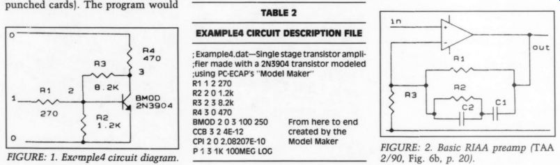
FIGURE: 1. Exampled circuit diagram.
FIGURE: 2. Basic RIAA preamp (TAA 2/90, Fig. 6b, p. 20).
------------
TABLE 2: EXAMPLE A CIRCUIT DESCRIPTION FILE
-----------
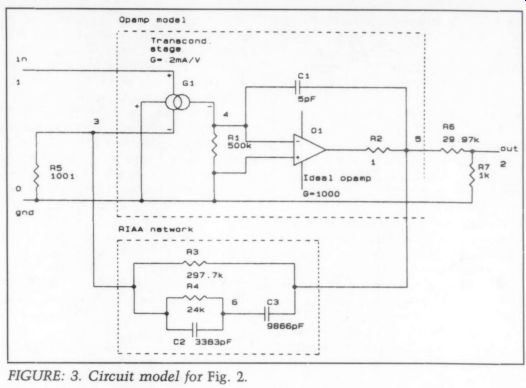
FIGURE: 3. Circuit model for Fig. 2.
... (which can be the wildest waveforms you can imagine) and what kind of data you wish as output. PSpice takes this list, constructs a mathematical matrix of the circuit, and calculates the output.
A full-blown system can calculate frequency response (amplitude, phase, and group delay), DC transfer curve, transient response, distortion, waveform Fourier transforms, the voltage/current/ power associated with a component, noise signal levels, and quiescent bias point. It can even calculate all this at different operating temperatures.
Options include Probe, to display waveforms and spectra graphically, a Monte Carlo statistical analysis that uses component tolerances you can specify to find those worst-case combinations. An option called Parts lets you build a component model from (limited) data-book information and measurements.
Also, the program requires a mathematical coprocessor in your PC. Not really within the amateur's reach. But there is an inexpensive limited capacity student version. P-Spice is so powerful it takes time and experience to use it adequately. But lately these types of programs have be gun to appear in the shareware circuit, which makes them particularly attractive to amateurs and professionals.
Share What?
For those unfamiliar with the term share ware: the shareware concept lets you legally copy a program and give it to others. You may not charge anything for it, except for copying and distributing (no more than $5 or $6). After you have examined the program and decided to use it, you are expected to register with the author and pay the license fee. You are considered using it if you would miss it if you did not have it.
Distribution of the program takes place mostly through shareware dealers, ? bulletin boards, and users. Many share ware authors (including PC-ECAP's) are members of the Association of Shareware Professionals. Its members agree to apply certain standards to their programs and to provide support for registered users. There even is an ASP ombudsman in case you and another member cannot resolve a dispute.
Shareware programs have low marketing costs, which is reflected in low-end prices. PC-ECAP costs $69 to register.
------------------
SIMULATION RESULTS EXPLAINED
I asked Mr. Volpa, the author of PC ECAP for his comments on my review, in particular on the differences shown in Table 5. His explanation follows.
Comparing the results of PC-ECAP to Mr. Williamson's calculations is mis leading. The latter represents the ideal response for an RIAA preamp. The circuit implementation is an approximation to this ideal.
In making the comparison, consider two things. How close is the circuit implementation to the ideal response? And how well does PC-ECAP simulate the circuit? Look at the basic circuit in Fig. 2.
As the input frequency is increased, the output level decreases due to the feedback shunting by C1 and C2. At very high frequencies, as C1 and C2 shunt R1 and R2 completely, the circuit degenerates into a voltage follower. Thus, the minimum gain is 1 or0dB. However, the ideal RIAA response continues to fall, even below 0dB. This means that the Fig. 2 circuit can never completely follow the RIAA response, even if all its components are ideal, and you should expect a deviation at high frequencies.
In the test circuit of Fig. 3, an out put attenuator of approximately 30dB is added, so the circuit gain can never drop below about - 30dB. This is precisely what is shown by Table 5. Iran a PSpice simulation on your circuit and compared the results to the PC ECAP's. They compare EXACTLY.
Now to answer the second question: the circuit is a good implementation of the RIAA response up to about 22kHz. This shows the useful ness of PC-ECAP. You may think a circuit has a particular response, but running an analysis shows you what it really is.
------------------------
This also gives you a right to technical support and update notes. The updates cost a nominal fee. For $10 more you get a printed manual instead of the manual on the disk.
Note that a lot of trust is involved. If nobody paid, no new or improved share ware would be produced.
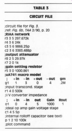
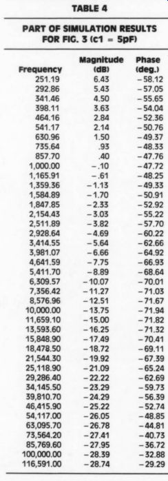
TABLE 4 PART OF SIMULATION RESULTS
PC ECAP
PC ECAP calculates the freq response (amplitude and phase) for a given circuit. Its simple but adequate built-in editor generates a text file that describes the circuit to be simulated (more on these circuit files later). On-line help is also available. The output data can be graphs (frequency versus amplitude or phase, but not both in the same graph), a tabular data list of output values, or a printout of each.
PC-ECAP provides a complete integrated environment for circuit simulation. Selecting or generating a circuit file, running a simulation, plotting, looking at the data, editing the circuit file, and so on are done from within the program.
Its user-friendliness is further enhanced by a menu-driven interface, obviating the need to memorize complex commands.
PC-ECAP's system requirements are modest. It can use MDA, CGA, EGA, VGA, and Hercules display adapters for its output plots. The printer output is tailored to 9-pin Epson-compatible print ers. You can also use 24-pin printers, but the page length may be incorrect. Sup port for 24-pin printers and the HP Laser jet series will be added in the near future.
The components PC-ECAP knows about are listed in Table 1. The program can handle circuits with up to 40 nodes and an unlimited number of components. It can best be explained by discussing a couple of typical uses. Figure 1 shows the circuit's program as ex ample4 and Table 2 describes the elements. Note the resistors with their connection nodes and values. The node numbers for ground and V,. are the same. PC-ECAP knows only AC, and for AC a power supply is transparent (or should be).
Now for the transistor. PC-ECAP has a clever feature to model transistors.
When you edit a circuit file, pressing F2 brings up the 'model maker."' You must specify the node numbers for b, e, and c, the collector current and current gain that goes with it, the gain-bandwidth product, and C_, (the internal feedback capacitor from collector to base). Model maker then puts in the lines you see in Table 2. The last line instructs PC-ECAP to plot the output signal at node 3 and the input at 1, starting at 1kHz up to 100MHz on a log scale.
The proof of the pudding is the eating: I built this circuit and measured 27.6dB midband gain on the real thing, while PC-ECAP calculated 27.73dB. Close. I guessed on the C_, (10pF) for the transistor I used, but I changed the model maker specification to 20pF to get the same - 3dB point on the bench as calculated by PC-ECAP (around 500kHz). The calculated phase shift at the -3dB point was given as 135°, which is correct. But I wanted to test the program with amore complex circuit of known properties, which I found (where else) in Audio Amateur.
The RIAA Connection
I turned to Reg Williamson's article in TAA 2/90 (p. 18) on the RIAA curve to get a benchmark. I built a circuit file for his Fig. 6b, which is shown in my Fig. 2. PC-ECAP includes a model for an ideal op amp, but the manual also gives a method to make a more realistic op amp model. This consists of a transconductance input stage followed by a high-gain amp, with a first-order rolloff.
The circuit model is shown in Fig. 3.
Those of you who followed the various discussions in TAA on op-amps will recognize the basic setup. The input transconductance stage G1 converts the input differential voltage to an output current, which in turn is converted by the load resistor R1 to an input voltage for the voltage gain stage O1. Capacitor C1 rolls the gain stage off from approximately 80Hz for a 5pF value. This stage is specified as having a gain of 1,000 at DC. Total DC gain is thus:
0.2mA/V x 500k x 1,000 = 100,000 or 100dB
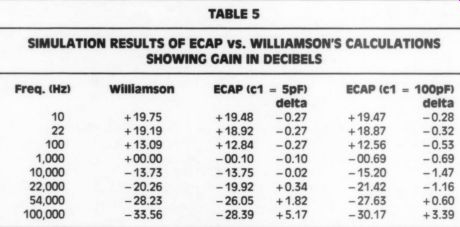
TABLE 5
SIMULATION RESULTS OF ECAP vs. WILLIAMSON'S CALCULATIONS SHOWING GAIN IN DECIBELS
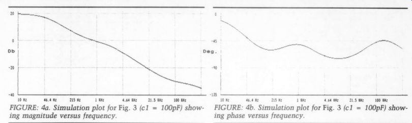
FIGURE: 4a. Simulation plot for Fig. 3 (c1 = 100pF) showing magnitude versus frequency.
FIGURE: 4b. Simulation plot for Fig. 3 (c1 = 100pF) showing phase versus frequency.
... with a frequency response rolling off as mentioned above: a cheap 741-type op amp. The resulting circuit file is shown in Table 3.
In his article, Reg Williamson provided a small BASIC program to calculate the RIAA components and the required gain versus frequency. The circuit as specified has a 30.97x gain. For comparison, I added an output attenuator to the model to get back to Reg's 0dB level at 1kHz.
Table 4 shows part of PC-ECAP’s results for c1 = 5pF. Table 5 shows selected values for two values of c1 compared to Mr. Williamson's calculations.
The model with the wider bandwidth (c1 = 5pF) is very close to the theoretical values for audio frequencies. In the case of c1 = 100pF, the deltas are higher and increase earlier. The open-loop gain of this model rolls off already from 4Hz. The high DC gain cannot be maintained at higher frequencies.
I am puzzled, though, by the high delta above 5.4kHz in the c1 = 5pF case. It is not clear whether this is a characteristic of the circuit or an inaccuracy in the model.
Yes, But . ..
As you can see, the program generates clear and useful graphs. Also, the data tables can be sent to a disk file and be processed by other graphing or presentation software. There are, however, a few re marks I must make.
It is not possible to save the graphs and overlay them on graphs from other simulation runs. This makes it much harder to compare results. The rather coarse scale marks do not help too much either.
You cannot set this scaling yourself.
What would help a lot here is a cursor that can be moved along the curve with readout of the x- and y-values. Note that these are things to make repeated use much easier and more efficient. The pro gram itself works fine.
The Map Is Not the World It is clear that programs like PC-ECAP can be very useful. You can verify a design idea and zero in on a particular result without having a load of components in stock. But like all powerful tools, a circuit simulator does not make you a seasoned expert. The paradox is that to get results that will correspond reason ably well to the real world, you must know what you are doing. It is like a bank loan: you can make creative use of it only if you do not actually need it.
In the above example on the RIAA preamp, if you find deviations from the benchmark, you are still back to your own knowledge and insight. Mostly you do not have benchmarks (that is why you use a simulator in the first place). Choosing the values for the op amp model carelessly gives unrealistic results. You should be able to recognize such a condition. Good planning is necessary.
Before I put together the complete RIAA circuit, I ran simulations on both the bare op amp and the combination transconductance amp/op amp. This gave me confidence that the model was reasonably accurate.
Another area where you can be misled is component values. For instance, you can multiply all resistors in the RIAA net work by 1,000 and divide all capacitor
REFERENCES
1. Spice, Guide to Circuit Simulation and Analysis Using PSpice, Prentice-Hall, ISBN 0-13-834607-0 (book only). Order #834614 (book plus disk) includes a student version of PSpice, limited to five nodes and ten transistors. This is a valuable book for anyone interested in analog circuit simulation.
2. PC-ECAP: The Public (Software) Library, PO Box 35705, Houston, TX 77235 5705, (713)-524-6394. Probably the world's largest shareware distributor, with thousands of programs. The latest version of PC-ECAP is 1.11, P(s)L disk #2273. values by 1,000 and get the same results.
But it would behave very differently in a practical realization (read the discussion on "reasonable values" by Reg Williamson in his article).
With care and a healthy dose of dis-trust, a circuit simulator is an excellent design and learning tool. Despite its limitation, PC-ECAP is no exception.
And for a price not much higher than a good soldering iron.
----------------
AD:
New England ANALOG
The Class A Design Manual is based on the author's experiences as engineer for Krell Industries and Mondail turers of high-end audio equipment. The work contains more than 100 equations and illustrations to offer analog hardware designers and kit builders a first hand look at the problems and solutions of real world designing not found in textbooks. Detailed discussions and schematics are given for unique designs which have been developed and tested by the author leading manufac
Constant Current Class A Reg. US Patent Office)
+»Class AD (Reg. US Patent Office)
« DC Regulator (no caps in the audio loop)
* JFET 3 Channel, 1, 2, or 3 Pole Crossover
+Noise Cancelling MC Headamp
« Balanced Circuitry
* Passive RIAA Audiophile quality double sided circuit boards are available for all projects
The Class A Design Manual
$25.00 & $2.00 shipping
NEW ENGLAND ANALOG THREE RUNDEL PARK, ROCHESTER, NY 14607
Please send $2.00 for complete catalog.
------------------
Book Reviews
AUDIO GLOSSARY
Reviewed by Peter E. Sutheim
The Audio Glossary, by J. Gordon Holt, 1990. Available from Old Colony Sound Lab, PO Box 243, Dept. A91, Peter borough, NH 03458-0243, (603) 924 6371, $9.95 (softcover), $17.95 (hard cover), $30 (limited edition).
A GLOSSARY, says a dictionary (which is not the same as a glossary), is a collection of specialized terms with definitions. The specialization here is entertainment audio-or what the lay reader would call “stereo ” (as in 'Wanna hear my new stereo? ”). It is the reference that, as an audio writer and broadcaster, I have wished for hundreds of times to respond to perplexed queries from readers and listeners. "Do you know,' goes the typical question, “of a book that would teach me the basic stuff or at least explain the terms so I could understand them?' Again and again, I would sigh and say I knew of none, at least no one book, to satisfy that need to know. Textbooks, professionals' handbooks, engineering manuals, directories, and consumer guides proliferate (and have, typically, a three-year half-life, or so it seems). But books directed at the ordinary Josephina, who wishes only to inform herself well enough to stare down an audio salesperson, have been few.
None of the more or less current books! has a glossary close to the scope of Holt's-understandable but hardly acceptable. Granted a glossary is a book in itself. Readers of these techno-texts feel a need (and, one could argue, have aright) to have things spelled out. What's more, few things aid clear thinking like wrestling to the ground a term such as absolute phase (or polarity) in 29 words, as Mr. Holt has done. Aside from the space requirements of a glossary, the labor demanded is of a heroic order (Holt's glossary boasts 1,900 definitions); moreover, many skilled writers lack the nearly lunatic methodicalness called for.
A good glossary includes alternative terms, draws distinctions between sim ilar notions, and, perhaps most importantly, tries to be reader-friendly. It is, therefore, full of cross-references, part ly to implement two conflicting goals:
comprehensiveness and conciseness.
Cross-referencing allows the definitions to be complete without needless repetition. Cross-references also adds depth to a glossary. They stimulate curiosity. Extensive cross-referencing is one of the most attractive features of Mr. Holt's book, which received extensive editorial assistance from fellow audio journalist Peter Mitchell.
Almost every time I found a technical term that, from the standpoint of a non technical reader, needed an explanation, one was available in its proper alphabetical place. However, I would have preferred not to guess at whether or not a term was defined elsewhere: I wish such terms embedded in a definition had been distinguished typographically (boldface, italics, small capitals) to pop out.
---ABOUT THE AUTHOR
Peter Sutheim has written for numerous audio and electronics magazines for the past 25 years. He heads the Audio-Visual Department at Occidental College in Los Angeles and produces a weekly audiophile radio show.---
The Choice of Words
What of the terms chosen and their definitions? Obviously, one of the most fundamental decisions is what to put in a glossary and what to leave out. Holt seems to have leaned toward inclusion, resulting in some eccentrically playful entries: blivet and thingamabob are in, but gizmo, one of my favorites, is not;
in the perhaps slightly more earnest department of subjective sonic description, chalky and plummy are in, but chocolaty is not.
For those wishing to make sense of subjective reviews using metaphors, Holt's glossary will be of some help, but words whose semantic fields overlap are not compared or distinguished. For ex ample, are sweet ('having a smooth, softly delicate high end) and silky ( “treble...that is velvety-smooth, delicate, and open ”) synonyms? Or could more be said about each and where they overlap? Editor Mitchell suggested a separate section of the glossary for subjective terms, but it was evidently not taken up.
I find this ironic because in the early years of Stereophile (founded in 1962), Holt promulgated a potentially helpful array of descriptive terms, two for each of the ten octaves of the audible spectrum. The first of each pair was used to name a deficiency in that band, the second an excess. The system never caught on, although the words were common and well chosen-perhaps because audio writers, all madly individualistic, would have had to grant Holt too much author ity. Absorbed into the mainstream of audio jargon, those words would have helped hundreds of equipment reviewers and millions of readers pin down more precisely the sonic attributes described, rendering subjective reviewing a little less arbitrary. Perhaps it's time to republish that list.
In its coverage of engineering, scientific, and mathematical terms related to home audio, Holt's book conveys the greatest authority. Almost all the terms for unfamiliar words and phrases you might find in a review are included. The book ranges widely, sometimes into surprising regions. Boolean logic is given a quick definition and so is three-phase supply, neither term in the first rank of audio-related terminology. My guess is they appeared in Stereophile and were tagged for inclusion.
I was surprised to find acceptor and donor (two arcane terms from solid-state physics) and surprised, though pleased, to find those terms meticulously cross referenced through doping, a technique used in producing semiconductors. A few oddball entries raise the eyebrows, such as v-audio ( “the audio portion of a video program ”) and bi-pole as distinct from dipole, even though the distinction is not made clear. (I have not been able to find bi-pole in any other dictionary I have, so I'm not sure what it means, either.) When Holt moves beyond the areas most familiar to him (he is not an engineer), the authority is wobblier. Tack ling acceptor, Holt adds to an opaque but correct one-sentence definition ('An electron-deficient dopant used to pro duce a p-type semiconductor material ”) the following unhelpful and almost ir relevant second sentence: “Indium is frequently used as an acceptor material in germanium. ” True, but when did you last see a germanium transistor in a new product? And is it useful to know the names of these elements without know ing anything about those properties making them useful in semiconductors? Music terms also contained boo-boos.
Holt defines bass clef as “the lower staff of two, which includes the key of F." It's not a staff at all but a symbol that designates the range covered by the staff it's written on. A staff so marked may not be the lower of two, even in the two staff piano scores implied; it may be one among several in an orchestral score. It no more and no less “includes the key of F"' than any other clef does-it's just that the F below middle C lies, by convention, on the fourth line up. Treble clef is clobbered with a similar solecism.
Is it important to have included these at all? And was it necessary to include piano, the instrument, along with the dynamic indication for soft? (Violin is not included, nor is cello, although violining is.) Some words ought to have been included that weren't. Uncorrelated is used in the definition of ambience extraction but is not defined. Correlated is, but only in the following sense: “high degree of similarity between the L and R stereo signals. ” This does apply in ambience ex traction, but leaves out the sense in which it was used. For example, Carver's autocorrelator is described as an ingenious analog noise-reducing device that gated-out noise by sensing its “uncorrelatedness, ” as contrasted with music, which had a much greater degree of correlation (harmonic relationship).
Dimension, a much abused buzzword in commercial writing, has its serious meanings, which ought to have been recaptured and fixed within an audio con text. A core concept of Richard Heyser's work was that music-listening is a multidimensional experience. Suitably chosen dimensions (such as pitch, intensity, width and depth, and time) are mutually exclusive and generally do not correlate well to the reduced number of dimensions in the audio signal (intensity and time). This, according to Heyser, has profound consequences, some seen in the seemingly irreconcilable arguments be tween the measurers (who deal with a reduced number of dimensions) and the listeners (who experience music holistically and yet try to make sense of what they hear in the engineers' universe of voltage and spectrum).
It is ironic this potentially major contribution to a resolution of the endless dispute between measurers and listeners has received so little attention since Heyser's death in 1987 and has been branded as too obscure to be helpful. A brief en try in Holt's glossary might have helped to stimulate more interest.
In a few cases, adding a word or two would have made a definition more complete, as with cathode-ray tube: “deflection coils control the position of the luminous dot."' To write “Deflection coils or plates ” would have included the family of electrostatic-deflection CRTs as well. Alnico, a magnetic alloy (not a compound as stated), contains significant amounts of iron and copper as well as the elements listed. These may be mere quibbles to many, yet it with this kind of thoroughness that real authority rests.
Then there are the off-the-wall, nutty inclusions that will make some giggle and others wince. Cassette: “(1) A removable case containing a length of magnetic tape and its supply and takeup spools. (2) A small cass. ” Or the second definition offered for backing: “investment capital." Concluding Remarks The personal preferences and prejudices manifested throughout Holt's book are endearing, if sometimes exasperating.
(See Holt's definition of hangover, hi-fi, exotic, and aleatoric.) They reveal it as the work of one man. Praiseworthy though the effort be, it is compromised by some of the qualities that commend it. One can't help wishing Holt had consulted a musician, a metallurgist, or even various dictionaries to check the accuracy of his definitions.
Errors in fact or judgment could have been fixed by peer review, a standard practice exhaustively employed in the preparation of every kind of authoritative dictionary. Holt's Audio Glossary is more like a Poor Richard's Almanac- pithy, witty, interesting, helpful, but hardly to be relied on as the final authority in the field.
I find this balance between the personal and the anonymously authoritative most exasperating about Holt's book. No reader would mistake Ambrose Bierce's Devil's Dictionary for a Merriam-Webster. The Audio Glossary, however, presents itself as a serious work larded with personal observations definitely not to be confused with Bluff Your Way in Hi Fi (Ravette, England, 1987). Yet reading it is like spending an evening with an af fable companion who seems to know what he's talking about, but who now and then pulls a fast one on you, straight faced-mostly intentionally, sometimes not. Fun, but not quite, well, reliable.
Aside from random minor editorial or typesetting errors, which are almost impossible to weed out completely in a first printing, a few more systematic typo graphical mistakes stand out. Hyphens appear where minus signs ought to be, sometimes confusing the sense of an expression. I also found it annoying, as mentioned earlier, that technical terms within a definition are not typographically highlighted.
The outcome of Holt's immense and well-intentioned labors is a useful but in complete book. Still, even with its faults, Holt's glossary deserves a place on every audiophile and audio writer's shelf. It's a courageous work. Anyone who thinks he can do better is welcome to try.
JGH responds:
Some of Mr. Sutheim's criticisms are well taken. If ever a revised Audio Glossary is published, they will be taken seriously. The others are not, and will not be.
A bipole is a dipolar device whose front and back radiation is in-phase. That is clearly stated in the definition.
e Although silicon is the semiconductor material in most modem bipolar transistors, germanium is the material with which most people who know a little bit about transistors are most familiar.
Vaudio is a useful, if ugly, term to use when discussing a device that accepts in puts from audio/video and audio-only sources.
The bass clef is defined as that staff on which F below Middle C is on the second highest line.
Perhaps I overestimate Mr. Sutheim's opinion of my encyclopedic knowledge base, but his suggestion that I wrote this whole thing off the top of my head, with out consulting experts in their fields and dictionaries in those fields, is at once flattering and insulting. Peter Mitchell, certainly a worthy “peer, ” spent many hours annotating and commenting on the original version, and practically all of his suggestions were followed. It was further checked by editor/publisher Ed Dell and his technical staff. Is Mr. Sutheim really suggesting that this should have been a committee effort! The reviewer seems to feel I commit ted a grievous sin by not legitimizing his apparent worship of the late Richard Heyser’s writings. I will grant him that Heyser was a master measurer, but I am not the only intelligent person in high end audio who feels Heyser's forays into theoretical psychoacoustics were more New-Age than scientific. Physiologically, our ears are strictly Old-Age; even after several billion years of evolution or a few days of creation (whichever way you look at it), they still respond to nothing more than frequency, intensity, and time, no matter how exhaustively and tediously we try to analyze the sounds fed to them.
As much as I would love to be deliciously irked by Mr. Sutheim's nitty picky review of my book, I really can't be. After all, the magazine I founded in 1962 created an environment where equipment reviewers who had never de signed so much as a plug, felt free to explain to preamp designers how they should have done things and to demonstrate their hypersensitivity to sonic pollution by pretending a barely audible imperfection was a FATAL FLAW. Mr. Sutheim's review is in complete harmony with this "madly individualistic" approach to reviewing.
But “of some help ” to those trying to make sense of subjective reviews! Sheesh! Peter, you're a nice young lad, but your judgment needs more time to mature. This glossary was originally conceived specifically as a lookup reference for readers of Stereophile, The Absolute Sound and the other magazines whose product reviewers hear differences be tween products and try to describe what they hear.
Originally, it covered only subjective testing terminology, and this is the book's strongest area. No other has even attempted to explain subjective audio's "'arcane ” terminology, let alone do it this well. (And no other will ever be written by the person who devised and pioneered the use of most of these terms.) The rest of the glossary was added after I came to the rather appalling realization that most readers of audio magazines don't know diddly-squat about anything electronic, and were not likely to go out and buy a $75 book to find out about it. Yes, there may still be inaccuracies in The Audio Glossary, but there are very few, and none of them is outright wrong-only somewhat misleading.
My only remaining question about Mr. Sutheim's review is: Why the ill-concealed hostility! Perhaps, someday, he will explain.
REFERENCES
1. The most recent glossary is Laura Dearborn's Good Sound (Quill Div. of William Morrow, 1987), which I have not seen, al though a telephone query to the publisher revealed it contains a three-part glossary of musical terms, audio terms, and listening evaluating vocabulary, with about 100 entries.
2. Ivan Berger and Hans Fantel's The New Sound of Stereo (New American Library, 1986) is good as far as it goes but rather uncritical in its acceptance of the questionable position that more advanced technology means better results, and is already somewhat dated (no fault of theirs). It has an index but no glossary.
3. Judy Davidson produced a breezy, illuminating, tradition-breaking home-audio guide, The Quickest, Easiest Guide to Stereo (Lancaster & Harrow, 1985; out of print), that tilted in the opposite direction (after all, no one said a flat earth has to be level).
---------
ADs
“Recommended for music lovers and audiophiles who want to know more about the physics of musical sounds. ”-Stereo Review
FUNDAMENTALS OF MUSICAL ACOUSTICS by Arthur H. Benade
Fundamentals of Musical Acoustics is a landmark book in its field, hailed for its astonishingly clear, delightfully readable statement of everything of acoustical importance to music-making. Though directed primarily to the music student who is taking an acoustics course, it is must reading for all musicians, music lovers and audiophiles eager to expand their musical horizons.
This book deals extensively with the fundamental modes of sound production and with the special sound-producing properties of musical instruments in common use today-as well as the human voice. It further explores the critical roles played by the room and by the hearer's auditory apparatus. The basis of scales and harmony and the craft of instrument-making are also discussed in this masterly text, which includes numerous illustrations, bibliographical information, and a stimulating section of "Examples, Experiments, and Questions' at the end of each chapter. 1990, 608pp., 6.5" x 9.5" ...BKD-5 $15.95
----------------
CHAPTERS
1. Closed-Box Low-Frequency Systems: Definitions History, Driver "Q"" and Enclosure Response; Woofer Selection; Box Size Choices and Parameters, Design Equations; Design Tables; Maximum Input; Cut-Off Frequency; Filling the Box; Dual and Compound Woofers
2. Vented-Box Low-Frequency Systems: Definition History; Driver Q & Enclosure Response, Selecting a Woofer; Alignments; Box Size; Design the Vent; Design Tables; Locate the Vent & Tune the Box; Q, Measurement: Subsonic Filters; Damping; Electronically Assisted Vent Types
3. Passive-Radiator Low-Frequency Systems:
History; Driver Q and Enclosure Response; Woofer Selections; Alignments; Box Size; Finding Delta for PRs Design Tables; Box Tuning; Q, Measuring; Augmented PRs; Dual-Woofer Formats
4. Transmission Line Low-Frequency Systems: Line Length and Damping; Tuning a TL; Enclosures; Woofer Selection
5. Cabinet Construction: Shape and Damping: Rectangular Boxes; Alternate Shapes; Box Damping
6. Mid- and High-Frequency Drivers: Application and Enclosures: Application; Driver Bandwidth & Crossover Choices; Two-Way and Three-Way Formats; Driver Separation and Horizontal Dispersion; Midranges; Mid and High-Frequency Enclosure Dimensions
7. Passive and Active Crossovers: Passive Networks; Operational Principles; Two-Way Filters; First-Order Networks; First-Order Reverse Polarity; Second-Order; Third-Order; Fourth-Order; Design Formulas, Unsymmetrical Two-Ways; Three-Way Crossovers; Three-Way APCs & Formulas; Driver Load Compensation; Series Notch Filters; Equalizing Impedance; Attenuation; Correcting Phase; Shaping Response; Crossover Inductors and Capacitors; Active Crossovers, Computer Aided Design for Crossovers
8. Loudspeaker Testing: Terms; Break-In; Calculating Resonance; Impedance; Compliance; Voice-Coil Inductance; Amp Source Resistance; Series Resistance; Air Volume & Driver Compliance; Driver Q; Frequency Response; Conversion Factors
-----------------------
If you had to invent a new language, where would you begin?
Back when high quality sound reproduction was a new idea and J. Gordon Holt was a staffer at High Fidelity magazine, manufacturers and journalists alike depended on the simple technical quality tests which everyone accepted as the yard sticks for performance. As the industry grew, equipment got better, competition fiercer, and technical reviewing became more crucial to sales managers. Before long, J. Gordon began to realize that reviewing was becoming more and more accommodating, and where the reviewers continued to rely on the standard tests, the measurement data began to look more and more alike.
Finally, in frustration. Holt left Great Barrington and headed for home in Pennsylvania where he founded Stereophile magazine in the spare room of his mother's house. He became convinced that although equipment tests and measurements were important, they no longer accounted for the differences he could hear. Two devices could easily measure the same and yet sound quite different.
Holt abhorred the tendency of the larger magazines to depend almost entirely on measurements, which he saw as a safe way to review without disturbing the manufacturer with any bad news.
Not only that, he realized that not one of the US audio publications was publishing reviews that were critical of equipment. In fact, in some cases they were ignoring some flaws.
However, if the reviewer wishes to review how equipment sounds, he faces a severe problem.
Our sense of hearing has the smallest vocabulary of any of our five senses. Thus, Gordon faced the difficulty of describing sound differences with all too few words with which to do it. He not only had to invent the techniques and disciplines of what has become known as "subjective reviewing" but also the language with which to do it.
Today. the magazine he founded has become a major force in audio quality judgments around the world. And almost all the vocabulary definitions are his work.
Seldom will you have the opportunity to purchase a reference work backed by so much primary research and experience. Few reviewers have spent more time and energy in an honest search for a defined, factual account of what matters in good sound reproduction techniques. In audio equipment reviewing, J. Gordon Holt is not only a pioneer but a master.
THE AUDIO GLOSSARY is the first publication of not only a vocabulary for sound description, but also a comprehensive overview of over 1,900 audio terms: technical and subjective. Your copy is waiting-at your favorite dealer-or order direct using the coupon below.
DEALER INQUIRIES INVITED
-----------------
Audio Amateur's Publisher announces:
RECREATIONAL THE WORLD'S FINEST ELECTRONICS JOURNAL THE POWER .
Elektor Electronics USA is a 76-page monthly with an average of 14 articles per issue, covering virtually every technology. Over 80% are construction features which include circuit diagrams, schematics, parts lists, and sources. The magazine's service department will supply circuit cards, software, firmware, and front panels for most projects.
Tutorial articles by outstanding authorities explain the latest technological developments.
Elektor Electronics USA construction projects are writ ten, with few exceptions, by staff engineers who design and test them with the aid of staff technicians and sup port people. All project prototypes are built and thoroughly tested before publication and also reviewed by the Dutch government's equivalent of the US Under writers Laboratories.
Elektor Electronics USA originates in Beek, The Nether lands. The multilingual staff not only produces the magazine's content, but also translates the articles into Swedish, English, French, German, Spanish and Portuguese. The magazine is published in separate editions for Sweden, Germany, England, The Netherlands, France, Spain, Portugal, Greece, India and Pakistan-and now The United States and Canada. The North American edition will feature new product and conference news as well as reader correspondence and free classified ads.
THE FUN SAMPLES FROM SIX RECENT ISSUES:
A Facsimile Interface for the IBM-PC, Automatic Power-down for PCs, A Mini EPROM Viewer, A MIDI Master Key board, Remotely Controlled Stroboscope, Rear Window Wiper Coupler, A Four-sensor sunshine recorder, Power Zener Diode, An Electronic Load, PLL sine wave generator, A Horn Loud speaker, Intro-scan for CD Players, A PC Servicing Card, Centronics A-D/ D-A converter, Acoustic Temperature monitor, Experimental all-waveband ferrite rod antenna, Image segmentation, Budget sweep/function generator, Transistor characteristic plots, An RS-232 Splitter/Multiplier, Digitally controlled preamplifier, All Solid State Preamplifier (2 parts), A Visual Hard Disk monitor, Coded locking security circuit, The digital model train: (13 parts), A wiring allocation tester, A video line selector, A Q meter, A Video mixer, Bridge Rectifiers for high output AC-DC and Multiplier use, Automatic Power line isolator switch, A 3-pen, 20" plotter with parallel port, An AC Millivoltmeter, An FM tuner board for your PC.
--------------
Ask TAA
By Gary A. Galo Contributing Editor
THE CD PLAYER AS TEST EQUIPMENT
IN ISSUE 3/88 OF TAA (p. 48) I reviewed a batch of test records from CBS Labs, including the CD-1 compact disc. I commented on the potential of the CD as a source for acoustical and electronic tests for applications other than testing CD players.
Over the years, many long-playing records have been made with pink noise bands, spot frequencies, warble tones, and other features. But whatever the analog disc's merits as a storage system for music, the LP was clearly a catastrophe as a test instrument. Even if the disc cutting equipment could be verified as “perfectly flat ” in frequency response, phono cartridges were rarely close.
This made LP test records extremely inaccurate for measuring anything other than phono cartridges, tonearms, and turntables. Measuring loudspeakers or room response would invariably produce errors of several decibels or more due to the inaccuracies of the analog playback system. Such tests were usually of little value.
The compact disc is an entirely different matter. Audiophiles will debate the sonic merits of the CD until the day before the millennium, but no one will deny that even an inexpensive CD player will usually measure very well by conventional standards. Ruler-flat frequency response, low distortion at maximum out put level, and a rock solid accuracy of pitch are undeniable virtues. This makes a CD player an attractive test instrument for the audio amateur and the speaker builder.
With a handful of CD test discs and a $200 player, you might be able to replace hundreds, or even thousands, of dollars of test equipment. A few new test CDs have come my way that indicate a CD test disk can be used for much more than testing CD players (Photo 1).
Compact Test Demonstrations Essais.
Pierre Verany PV.784031 (1 CD).
Available from Old Colony Sound Lab, PO Box 243, Peterborough, NH 03458, (603) 924-6371.
In TAA 1/89 (p. 46) I reviewed an excellent two-CD test set {from Pierre Verany. Those discs are made specifically for testing CD players and are in dispensable. This disc does not duplicate ETRE ...
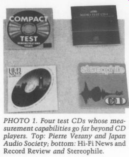
PHOTO 1. Four test CDs whose measurement capabilities go far beyond CD players. Top: Pierre Verany and Japan Audio Society; bottom: Hi-Fi News and Record Review and Stereophile.
... the previous set. Instead, it provides a selection of extremely useful tests for acoustical measurements.
What immediately caught my attention was the inclusion of 1/3-octave warble tones from 16Hz to 20kHz. As far as I know, Pierre Verany is the first to offer them on a CD. Most warble tone generators, including the Old Colony KK-3 and the Audio Control Richter Scale, have the warble frequency set around 5Hz. On the Pierre Verany CD, it changes randomly, using a principle they call Aleatory Frequency Modulation.
Warble tones offer an important advantage over filtered pink noise. The latter results in phase shifts that amplitude modulate the noise. This creates large variations in level, which are worse at low frequencies. Warble tones are free of this problem.
Although pink noise is useful for measuring the combined response of a room and loudspeaker, it cannot be expected to simulate an anechoic loudspeaker measurement because early reflections from the room will also affect it, even with the microphone 1 meter from the loudspeaker. Warble tones minimize the effects of early reflections and the random warbling method used on this test disk should reduce them even further.
With the microphone positioned out in the reverberant field, room response can also be measured.
The random warble tones have one drawback. Unless your decibel meter is damped to give a true average reading, the level will jump around and make the measurement difficult to interpret accurately. Most AC voltmeters are too fast in their response to be useful. Most SPL meters, however, have a “slow ” response setting that works well. One major annoyance-all of the warble tones are contained on a single track with no indexing. You must write down the time location of each frequency if you wish to return to specific spots on the disc.
The Pierre Verany disc also contains wideband white noise and pink noise, for those who have a real-time analyzer. The frequency response of any piece of audio equipment can be checked with the band containing Y;-octave sine wave tests.
These tones can also be used for tape recorder alignments, including bias and equalization.
Don't expect to verify that your latest power amplifier is flat from DC to be yond daylight. Remember, the CD is limited to a 20kHz bandwidth, and it is not possible to record tones higher than this on any test disc. 20Hz is the low frequency limit for these tests. Like the warbles, individual indexing is not used for these tones.
Pierre Verany also includes tests for channel identification, loudspeaker phasing, and dynamic range. The disc has 13 musical tracks (one of them is a steam locomotive, but I prefer it to the country music track). The booklet is in French and English.
Audio Test CD-1-91 Test Signals for Home and Laboratory Use. Japan Audio Society YDDS-2 (1-CD). $25 plus $2 shipping and handling from DB Systems. Order #DBP-CD-1.
The Japan Audio Society (JAS) test disc begins with wideband pink noise tests for channel identification and phasing, followed by left and right tones for cross talk measurements. These can be used to measure channel separation on any preamp or power amplifier. Sine wave spots at };-octave intervals are included, from 20Hz to 20kHz. Like the Pierre Verany disc, these are useful for frequency response measurements on a wide variety of audio equipment, as well as tape recording alignments.
The producers of this disc were much more thoughtful than Pierre Verany; each frequency is on a separate track. For those who do not have a real-time analyzer, but have a need for pink noise, filtered 1/3-octave pink noise bands are also included. Again, each band is on a separate track. Wideband pink and white noise are also included.
Sweep signals from 20Hz to 20kHz are offered in L, R, and L +R formats. The sweeps of 50sec and 150sec duration will be useful only if you have a chart recorder. With suitable filtering, you can perform intermodulation distortion tests with the JAS CD. The SMPTE test is simulated with 60Hz and 7kHz tones in the standard 4:1 ratio. You can measure high-frequency IM distortion with the 14 and 15kHz tones, mixed 1:1. Loud speaker builders will find the tone-burst measurements extremely useful. Tone bursts at 24 frequencies are included, from 20Hz to 11.025kHz, along with the standard 1kHz EIA/IHF tone bursts. The disc also has signals for measuring impulse response.
You can check phase and polarity characteristics with the raised cosine wave signal. It contains only half of the cosine wave, so you can clearly distinguish phase shifts from polarity inversions.
This test is best accomplished by triggering your dual-trace oscilloscope on the CD player's output, while observing the player's output on the top trace and the output of the equipment being measured on the bottom one.
The Japan Audio Society test disc contains a number of tests not found on other CD test discs, and the individual track numbers on each tone and test make it a pleasure to use. This JAS CD is an extremely well thought out package.
Hi-Fi News and Record Review Test Disc II. Hi-Fi News and Record Review HEN-015. $30 from Old Colony.
Hi-Fi News and Record Review, the respected British publication, has produced a test disc with one feature not offered on any others I have seen-spot frequency tones below 20Hz. The HFN/ RR CD begins the spots at 2Hz, followed by 4, 8, 17, and 20Hz sine waves. A total of 12 tones are included from 20Hz to 20kHz, not enough to cover every 1/3-octave, but sufficient for most frequency response measurements and tape deck alignments. Since the other discs I re viewed do not allow measurement of the low-frequency roll-off point of preamps, amplifiers, and CD players, this disk fills a serious void.
The HFEN/RR disc is also the only test CD with tracks specifically for tape deck alignment. These tests contain tones at 315Hz, 10kHz, and 3.150kHz, which will be most useful on cassette decks.
Three swept frequency tracks are also included. You can measure TIM distortion using tracks containing 19 and 20kHz tones at a 1:1 ratio. Like the JAS disc, you will need appropriate filtering or a spectrum analyzer.
The disc's impulse test can measure frequency and time domain response with an FFT analyzer. Tone bursts and tracks for testing CD players are also included. You can check low-level linearity with calibrated 1kHz tones from 0dB to -100dB in 10dB increments.
The Hi-Fi News test CD also includes a variety of musical tracks, including Denon’s anechoic recording of Mozart's Marriage of Figaro overture. This recording was made with 29 microphones. The selection is also repeated with digital reverberation simulating the Amsterdam Concertgebouw, the Vienna Musikvereinssaal, and Boston's Symphony Hall.
Several purist stereo microphone techniques are also demonstrated, ranging from spaced omnis to crossed figure 8s.
Stereophile Test CD. Stereophile STPH-002-2 (1 CD). $6.95 plus $2 ship ping and handling from Stereophile magazine, Record Dept., PO Box 364, Mt. Morris, IL 61054, (800) 435-0715 for credit card orders.
Let me state up front that I write for Stereophile and that they did not ask me to review this product. I thought it would be appropriate to include the Stereophile CD, since it also contains 1/3 octave warble tones for low-frequency room and loudspeaker analysis below 200Hz.
Unfortunately, something went wrong in the preparation of the warble tone tracks. The notes indicate that the Old Colony generator was used and that the warble frequency is approximately 5Hz.
But, the actual warble frequency is much higher and the sound more closely resembles a machine gun than the Old Colony generator.
I built an Old Colony generator several years ago and use it extensively for loud speaker measurements. Mine does warble at 5Hz, so I suspect a component is either incorrectly installed or way out of tolerance in the Stereophile generator. If warble tones are your only reason for wanting this disc, I would avoid purchasing it until the problem is corrected.
Stereophile's Test CD contains channel identification and phasing tests, but not with the usual boring test tones or pink noise. Publisher Larry Archibald's dog Ralph provides a healthy bark for these tests. Perhaps the most interesting section of this disc, especially for TAA readers who do their own recording, are the microphone comparisons. Stereophile founder J. Gordon Holt reads from his 1963 article "Why Hi-Fi Experts Disagree. ” Eighteen different micro phones, in succession, are used during this 6.5 minute segment. Even if you are not an amateur recordist, you will find the widely varying sounds of professional recording mikes highly educational.
Several musical recordings, engineered by members of the Stereophile staff, are offered, including four by J. Gordon Holt.
Like me, Gordon has a preference for ORTF stereo recording. This method was developed by French National Radio and Television (Office de Radiodiffusion Television Francaise). It consists of two cardioid mike capsules spaced 17cm apart and angled at 110°. Alive recording of the Delaware Symphony Orchestra playing Armas Jarnefelt's Praeludium is extremely natural and realistic.
Also noteworthy is an organ recording engineered by Peter W. Mitchell and Brad Meyer. Their recording of J.S. Bach's transcription of Vivaldi's Concerto in d minor was also made with an ORTF stereo pair, supplemented by two widely spaced omnis to enhance the hall ambience and the bass frequencies.
I hope Stereophile will fix the warble tone problem. If they do, their test disc will be a useful tool for low-frequency room analysis. In fact, I would like to see the ;-octave warble tones extended to 20kHz. The disk is currently quite full, with a total time of 70:54. I would rather eliminate one of the musical tracks to make room for warbles tones across the entire spectrum. This would make the Stereophile disk even more useful than the Pierre Verany for those who do not own heavily damped, average reading decibel meters.
These discs show that test CDs can be useful for testing many audio components other than CD players, including amplifiers, tape recorders, loudspeakers, and listening rooms. Probably no single disc will offer every test you will need, so I am sure many readers will purchase two or three of them. The Pierre Verany, Japan Audio Society, and Hi-Fi News CDs all offer a variety of extremely useful tests. Stereophile's CD will also fill a void if the warble tones are corrected and extended to 20kHz.
NEW FROM MOGAMI AND MARSHALL
Marshall Electronics, Inc. offers two new Mogami Neglex series gold-plated connectors. [ have found them excellent for high-performance audio equipment (Photo 2). Over the past few years I have used a large number of Neglex 7550 RCA plugs and 7552 jacks. These gold-plated connectors performed well when first in stalled, but all developed a green corrosion within a year, adding a layer of sonic grunge to my system. Fortunately, Mogami's new connectors appear to be free of this problem.
The 7551 RCA plug has a very high quality gold-plated finish, one of the shiniest I have seen. The center pin is solid, rather than hollow and the solder connection is made at the rear. The cover is sand-blasted nickel and will accept cables up t0 0.236" (mm) in diameter, including Neglex 2534 cable. Red plastic rings for right-channel connectors aid in identification. Several high-priced inter connect cables use this plug, including the Tara Labs Paragon Interconnect sold by Audio Advisor. By the time you read this, Marshall will also be stocking the 7204 connector. It is virtually identical to the 7551, but the heavy black chrome cover accepts cables up to 0.315" (8mm) in diameter.
One limitation common to most chassis-mount RCA jacks is the method for connecting the ground. Nearly all contain a solder lug that is forced against the jack when the bolt is tightened. This puts a contact in the ground path, which I find undesirable. The Neglex 7557G has no such connector. The jack's shield is a solder lug that protrudes from the threaded portion at the rear, eliminating the contact point. Each 7557G has a nut, lockwasher, and insulators.
This is one of the best RCA jacks I have used and mated with the 7551 plug, it offers performance that will complement your finest audio projects. Old Colony also sells these connectors. The 7551 plugs are $18/pair and the 7557G jacks are $16/pair.
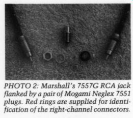
PHOTO 2: Marshall's 7557G RCA jack flanked by a pair of Mogami Neglex 7551 plugs. Red rings are supplied for identification of the right-channel connectors.
Hugh Neep at Marshall Electronics sent me a sample of their new Sound Runner Flat Speaker cable (Photo 3). This cable is a finely stranded, 16-gauge wire, with oxygen-free copper (OFC) conductors and PVC insulation. Hugh says that this is not intended to be a 'state of the art’ speaker cable, but should offer cost effective performance when a cable must be laid under a carpet.
Flat speaker cables are rare. One other that comes to mind is the AudioQuest F-14, which contains four solid OFC cop per conductors. Sonically, F-14 is very good, but the solid conductors are not particularly durable. I suspect that F-14 would not hold up very well if placed under a carpet that gets heavy traffic. The Sound Runner cable is extremely tough and should maintain 'like new’ performance under these conditions. If you must run cable under the carpet, it is a good choice.
Marshall Electronics, Inc., PO Box 2027, Culver City, CA 90230, (213) 390 6608, FAX (213) 391-8926.
SESCOM RACK CHASSIS
Last October, at the Audio Engineering Society convention in New York City, Ed Dell and I had a nice chat with Frank Miller, president of Sescom, Inc. Sescom is a regular exhibitor at AES conventions, and manufactures a number of ...
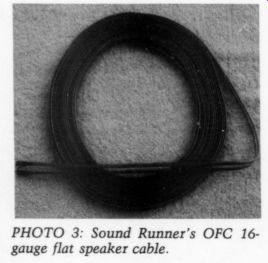
PHOTO 3: Sound Runner's OFC 16 gauge flat speaker cable.
...items of interest to audio amateurs. It's always a pleasure to talk with Frank.
Unlike many manufacturers who cater strictly to the large-volume, factory assembled pro audio industry, Frank has a keen interest in our needs and enjoys building equipment. One item in his booth which caught my attention was an all-aluminum rack chassis, which, as it turns out, is available in nine different sizes.
I have complained at least once in this column about the lack of attractive chassis which weren't made of steel.
Permeable metal is not a desirable material to use for audio cabinets, due to the sonic degradation caused by eddy current effects. I was delighted to find a line of chassis which did not contain steel. I asked Frank if he would submit a sample for review, in particular, model 2RU10, measuring 19 x 10 x 3.5 inches.
Frank was more than happy to oblige Audio Amateur, and in due time a sample arrived.
The Sescom rack chassis are supplied unassembled. Each unit consists of top, bottom, front and back pieces, as well as two L-shaped side pieces with holes drilled for standard 19-inch rack mounting. Four aluminum channels and eight machine screws hold the other six pieces together. All pieces except the front and back are black anodized. The front and back pieces are natural brushed aluminum, which allows the user to label them with black rub-on lettering.
The modular construction of these chassis allows drilling, punching and lettering of individual pieces before the en tire chassis is assembled. This makes the metal-working part of the project much easier. Completed, you have an extremely attractive piece of equipment.
These chassis will make ideal housings for preamplifiers and electronic crossovers. Sizes range from 19 x 5 x 1.75 inches up to 19 x 10 x 5.25 inches. The bottom plate is a bit too thin to support heavier power transformers, but these could easily be mounted on one of the side pieces, which are quite robust.
Sescom also carries a line of smaller aluminum cabinets, which are not rack mountable. Eight models, varying in size from 4 x 3 x 2 inches up to 8 x 7 x 4 inches, are available. If you prefer to house the raw, unregulated portion of your power supply in an outboard chassis, as I do, these will make excellent companions to the rack chassis. The largest models are big enough for an oversized toroidal transformer, hefty rectifier bridges, and filter capacitors.
This approach keeps AC out of the main chassis, while allowing you to place the regulation as close to the circuitry as possible.
Sescom is perhaps best known for their excellent audio transformers. If you are building a mixing console, or have other needs for low level audio transformers, Sescom has an extensive line. A copy of their catalog is free for the asking. It is not fancy, printed on newsprint, and the aluminum chassis are listed on a separate photocopied sheet. But, the bare-bones catalog helps keep very reasonable prices for the consumer. Sescom's $10 minimum order puts them within reach of any TAA reader. Sescom, Inc. 2100 Ward Dr., Henderson, NV 89015-9998, (702) 565-3400.
READERS' QUESTIONS
My replies to readers Harold Barstow and Eugene Welker regarding home recording equipment deserve a further comment or two (TAA 4/90, p. 47). First, due to an editorial change, my comments on the sound characteristics of Dolby and dbx noise reduction were altered a bit. When I noted that instrumental scoring was not bothered by dbx's harshness in the high frequencies, I was referring specifically to the instrumental combinations found in percussion ensembles and contemporary music groups. The slight harsh ness dbx adds to massed strings and choral sopranos does not apply to these ensembles.
Since I wrote that column, Sony has introduced an excellent affordable DAT recorder. The model DTC-700 uses their High Density Linear Converter circuitry and an extremely smooth four-motor transport. The D/A converters use 64X oversampling. Although I have not re corded with the DTC-700, I have heard one and was very impressed with its performance. Although the list price is $900, many mail-order firms are selling it for $799, including International Electronics World, 6330 Frankford Ave., Baltimore, MD 21206, (800) 638-3920 or (301) 488 9600. Professional quality digital recording has never been more affordable.
In my last column I also discussed a high-performance regulated power sup ply using Linear Technology IC regulators. mentioned Walt Jung's preference for power transformers with electrostatic shielding between the primary and secondary windings. Unfortunately, I did not know of anyone manufacturing electrostatically shielded toroidal transformers. Reader P. Best of Dorset, UK has found a source. He tells us that such transformers are available from Holden & Fisher, Ltd., 64-72 Glentanar Rd., Glasgow, Scotland. He also notes that the shielded transformers are more ex pensive than unshielded ones. Overseas shipping on such heavy items will also be expensive, particularly if you have them shipped by air.
I have also found a US source for this type of transformer. Toroid Corporation of Maryland offers what they call “static shielding ” as an available option on their transformers. Quoting from their brochure, 'Static shielding may be required to minimize capacitive coupling be tween primary and secondary windings when the transformer is used in an extremely noisy environment. ” Audio amateurs whose power lines suffer from RFI and other electrical interference should find the use of these transformers sonically beneficial. Using electrostatically shielded power transformers in your equipment may eliminate the need for costly power-line conditioning ahead of your power cords.
Pricing is on an individual basis. Write or call with your specific requirements.
Toroid Corp.'s address is 6000 Laurel Bowie Rd., Bowie, MD 20715-4037, (301) 464-2100, FAX (301) 464-4657.
Reader Larry Campbell, whom we have heard from before, is having diffi culty getting a pair of three terminal IC regulators to operate properly. He is using the 7818/7918 combination and has no problem with the negative regulator, but cannot make the positive one operate properly with any combination of pin configurations.
The 7818 positive regulator has this pinout: 1 is IN, 2 is GND or COMMON, and 3is OUT. The 7918 negative regulator is different; pin 1 is GND, 2 is IN, and 3 is OUT. The pins are numbered from left to right as you face the plastic side of the regulator (the metal tab is on the back).
If your 7819 was originally connected incorrectly, you may have damaged the regulator so that now it will not work even when connected properly. I would try anew 7819, making sure the connections are correct.
Fred G. Sutton needs advice on modifying CD players. He asks if any of the TAA modifications for the Magnavox players are applicable to his five-year-old ADC CD-100X player. He would also like to know if his CD-100X is worth modifying and if any Old Colony kits can be used with his machine.
A few years ago I would have responded positively to his first question. Since Philips introduced the first 4X oversampling players in the summer of 1986 (the original CDB-650), many improvements have been made in the digital circuitry of CD players. Philips' upgrading of the digital filter and DAC (see 'Ask TAA" 3/90, p. 49) has kept their technology competitive with recent offerings by other manufacturers.
Spending money modifying any CD players using pre-650 digital technology is not worthwhile. No matter what you do with analog circuitry and power sup plies to these earlier players, you are still saddled with their limitations. Poor low level linearity, a single D/A converter shared by two channels, and the excessive high-frequency phase shift found in players designed prior to oversampling and digital filtering all add up to sonic limitations that cannot be fixed else where. Applying POOGE-4 techniques will certainly improve older players, but their performance will not even be close to more recent players with the same mods. I would purchase a new Philips or Magnavox player and use it as a modification vehicle.
One Old Colony kit could be fitted to your CD-100X. The inexpensive KW-1 modification will work fine, since the CD-100x uses dual IC op amps following the standard pin configuration. I would replace U-504 and U-505 with the 5535s or AD-712s (see comments below on op amp selection). You can also eliminate the “safety ” resistors in the power supply rails to U-505.
The 330uF Panasonic capacitors are probably better than the electrolytics used for C-530 and C-540. They were only 2.2uF since they were terminated by a 100k load, rather than the 4.7k resistors used by Magnavox. You could use a high quality film cap here; 5uF would be just fine. Even if you buy film caps, you will be spending around $25 on you CD 100X, about as much as I would recommend on such a dated player. If you are thinking of a POOGE-4 level of modification, begin by replacing the CD player.
Reader Mark McCaslin has a related question. He wonders why Old Colony gives buyers a choice of op amps for the KW-2 kit. The 5535 and AD-712 are both fine devices, but they are not identical in their sonic performance. The 5535 has better drive capability, which is important if your cable runs are unusually long.
The AD-712 is a bit more detailed in the ...
--------- FIGURE 1: A 2N5457 N-channel FET can be used as a current source. R45, should be trimmed for the desired drain current.
... high frequencies, but the difference is subtle. I would change the pull-down resistor values if the AD-712 is used. The 3.92k resistors pull 4mA of current from the 5535s. The AD-712s sound best with about 2mA of current. A resistor of 6-7k will work fine.
I recommend using a pair of machined pin, gold-plated IC sockets, along with a pair of 8-pin gold-plated headers, for this mod. After removing the old ICs from your player, solder in the machined pin sockets. Then, carefully solder the new op amps and the pull-down resistors to the top of the header. This makes an extremely neat arrangement and allows you to make comparisons of different op amps easily. Simply build up as many op amps as you wish on headers and com pare their sound by swapping them in and out of the sockets. Turn the power OFF before switching op amps, however.
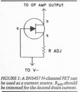
Biasing op amps for Class A operation can also be done using a current source rather than a pull-down resistor. This method, which I discussed in Ask TAA 2/90 (p. 47) is sonically superior to the pull-down resistor method. In that column I suggested using 2N5457 FETs, hand picking them for 2mA. Since that time, I have found that most 2N5457s will not result in 2mA of current. I got lucky with my first batch, only to find that most of the transistors in my next two orders were off by as much as 100%.
The solution is the same as the one shown in Fig. 3 of issue 2/90: add a resistor between the source and the negative supply. For new subscribers, the correct connection is shown in Fig. 1.
The drain of the FET is connected to the op amp's output. The gate is connected directly to the negative supply, and the source is tied to the same point through the resistor (Ryn).
I have needed resistor values from 125-375 ohm to produce the desired 2mA.
You will need a digital multimeter with 1mA resolution on the current scale.
Simply connect your milliammeter be tween the op amp output and the drain of the FET while swapping resistors. I usually set up a breadboard circuit, with the op amp set as a unity gain voltage follower, to test the FETs. I simply plug the FETs and resistors into the bread board and sort them according to the necessary resistor value.
You can connect and disconnect the FETs and resistors with power applied to the circuit; no potential for damage exists. If you must perform the test in side your CD player, I would definitely cut power before changing components.
You could damage your CD player if a resistor or transistor lead accidentally touched the wrong component.
The 5535 requires 4mA of current for best performance. Many 2N5457s will yield 4mA without the resistor. The AD-712s require 2mA, which will normally require trimming the FET. Most other op amps I have used will work well with a 2mA current source. The 5535 is unusual. One final point: once you have trimmed the FETs for the amount of current needed, the current will be the same with any op amp.
Be careful of your connections. With the standard dual op amps used in the KW-1 and KW-2 mods, pins 1 and 7 are the outputs and pin 4 is the negative supply. Single op amps normally use pin 6 for output and 4 for the negative rail.
Gold-plated sockets and headers are available from Mouser. The sockets are Augat, #506-508-AG10D. You will have a hard time finding 8-pin gold headers, though. I buy 16-pin headers and cut off eight of them. If you are careful, you might be able to get two 8-pin headers out of a single 16-pin assembly. I usually cannot make a cut that fine, so I wind up losing the other eight pins. The headers are made by Circuit Assembly, #544-16P-02. Mouser's toll-free number is (800) 346-6837.
Audio Aids
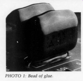
PHOTO 1: Bead of glue.
HOT GLUE I HAVE FOUND THAT a bead of hot glue does a good job of supporting electrolytic capacitors and other bulky components on printed circuit boards. The glue re mains somewhat pliant after it cools (Photo 1), and the bond is not so strong that it can't be broken when replacing components. This miniature glue gun from a local hardware store does a good job dispensing small amounts of glue (Photo 2).
RON SAWYER, Seattle, WA 98144
A PERFECT FIT I DON'T LIKE HEAT-SHRINK tubing. It's stiff, expensive, and awkward to work with. Even if you buy an assortment, the size you need is invariably missing.
Finally, many places are too crowded to get heat into, or the parts themselves are too delicate to withstand the necessary blast of heat.
A solvent-based shrink system is cheaper, gentler, and gives far better results. You probably already own a modest supply of vinyl tubing. In addition to the store-bought variety, it disguises itself as cable jacket, insulation, and even aquarium tubing. All you need to get started is a can of Zylol or Toluol (toluene) and an unused pint paint can, both available at any good paint store.
First, a word of caution. These are paint thinners and should be handled as such. Read the safety instructions on the can. Cover all containers whenever possible, store only in metal cans, and do not flush down the sink. Dispose of by dumping used liquid into a bucket of dirt, or by donating unused solvent to a painter.
Solvent-based systems work backwards from normal. Start out by selecting a size slightly smaller than the finished diameter, and cut to length. Pour enough solvent into the paint can to cover the tubing, and let soak for at least five minutes. The tubing will swell and become rubbery.
After removing the tubing from the solvent, you will have about a minute before it starts to regain its former size.
Don't be afraid to force it over moderate sized bumps, but if you go overboard, it will probably split under the strain as it dries.
Except for the presoak, this system is about as fast as heat shrink. To save time, you can pre-treat tubing in the solvent and store it for as long as you wish.
I have kept some of my tubing soaking for several years without deterioration.
ROBERT MCINTYRE, Maumee, OH 43537
STICKEM LICKEM--THOSE TEMPORARY' LABELS on your equipment may be more permanent than you think. The next time you can't get one off, or it leaves a messy residue, try this simple trick.
You will need cotton swabs, a wooden or plastic spatula, facial tissue, a light penetrating oil such as WD-40 or LPS-1 and, for you really impatient types, a sharp single-edge razor blade.
Begin by spraying the label with a generous amount of penetrating oil and spreading it around with a swab. Let this set for around half an hour, then probe cautiously with the swab. If the label appears loose, try breaking the bond by rubbing the swab near the center of the paper. You may be able to catch the edge by gently sliding the razor blade through the oil with a shoveling motion.
Your label, of course, will be the one whose adhesive has turned to concrete.
Use the spatula to apply just enough pressure to score the paper and not mar the work. Spray it again, Sam.
After the work sets awhile, you should be able to roll off bits of dried paper. Once you expose the adhesive, the oil will quickly dissolve it, and you can clean it up with more oil and facial tissues.
Whether you clean off the remaining oil depends upon the nature of the surface. On wood, you merely spray the rest of the surface and polish, but matte finishes require that you remove the oil completely. Use alcohol and a soft rag- facial tissues are too abrasive and may scratch.
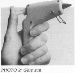
PHOTO 2: Glue gun.
Most pressure-sensitive tapes and their residue will clean right up without extreme measures. Neither oil nor alcohol will damage most surfaces, but if in doubt, by all means test before using.
ROBERT MCINTYRE
Maumee, OH 43537
TOWARDS A NO COMPROMISE TONEARM UNTIL VERY RECENTLY, the tonearm has been the major weak link in Thorens turntable systems incorporating a proprietary arm. In particular, the TP-16 Mark III, used in the TD-126 Mark IIIC, TD-147, early TD-320, and Jubilee, has a number of compounding structural compromises which degrade the overall sound reproduction of the turntable system.
The TP-16 Mark III has an attractive but complicated headshell design that makes it almost impossible to tightly secure phonograph cartridges. Also, the headshell rotates to adjust for azimuth alignment, but you cannot tighten it once proper alignment is achieved. Finally, the arm tube is a two-piece mechanism with a bayonet attachment. Although this makes cartridge changing easy, the structural rigidity of the tonearm is compromised. The net result is an audible deterioration in transient detail and dynamic range, lending a rounded and softened sound to the music.
This is unfortunate, not only because the basic Thorens turntable is generally
excellent, but also because the TP-16isan otherwise excellent tonearm. For example, the bearing tolerances and friction levels in both planes are first rate, exceeding the quality of some highly touted audiophile favorites. Moreover, the anti skating mechanism is a magnetic system which varies the anti-skating force, de pending on how close the tonearm is to the end of the record.
In contrast, many audiophile tone arms still use the comparatively crude nylon fish line and sinker system, which allows no such variation. The Thorens arm also allows vertical tracking adjustments through the use of two 2-mm Allen screws mounted at the base of the tonearm. Finally, the tonearm's vertical tracking force is dynamically balanced, which carries the potential for improvements in tracking over more conventional systems.
If you own a Thorens turntable with the TP-16 Mark III tonearm, you can substantially improve the sound quality of your turntable system by eliminating the detachable wand and non-locking head shell mechanisms from the arm. The modification requires a certain amount of mechanical dexterity and patience. Be prepared to set aside a Saturday to complete the operation.
The Modification To modify the tonearm you need parts from the "Mark IV ” tonearm, which first appeared on the $2,295 Phantasie turn table by Thorens. The parts are all avail able from the manufacturer, and they include the TP-16 Mark IV one-piece, medium mass arm tube (#7-876-400,
$40), the TP-68 locking headshell (#57 891-01, $16), and high-mass counter weight (#Y7-875-011, $15). The total cost of the conversion is $71, plus $2.50 shipping and handling. Parts requests should be directed to Noel Conley, Thorens Technician, Epicure Products Inc., 25 Hale St., Newburyport, MA 01950.
(This modification will probably void your turntable's warranty.)
GIMBAL ARM Rp -- TUBE s U-SHAPED NAIL
You will need a soldering gun, screw drivers, a pair of regular pliers, a pair of needle-nose pliers, a U-shaped nail, and a vegetable twist-tie wire.
Begin by removing the detachable wand and counterweight assembly from the tonearm. Part of the counterweight will hang down from a wire after detachment. Let it hang.
Remove the platter and detach the turntable platform from its base, using the appropriate screwdrivers. You cannot completely separate the platform from the base (because of wires), so it's a good idea to use plenty of towels to prevent the underside of the platform from scratching the base.
Next, remove the remaining arm tube from the tonearm gimbal. To do this, you will normally need to use a special screwdriver with a two-pin head. The availability of this tool is in question.
Even Thorens in Massachusetts doesn't have it. However, you can use a U shaped nail, available at almost any hardware store, to achieve the same end (Fig. 1).
To remove the remaining arm tube, use the pliers to adjust the distance be tween the two tips of the nail. Once the two tips match the two holes in the gimbal screws, you can loosen one screw to take out the arm tube. It's a good idea to write how many turns you make, to gauge the proper tolerances when in stalling the new tube.
Once the old tube is disengaged, you will see a group of colored wires attached to it and leading into a hole in the gimbal. These wires can be cut and dropped down the hole. Do not cut the counterweight wire.
Now you can install the new arm tube. To facilitate funneling the new wires through the gimbal hole, use a twist-tie wire. Strip the paper from the wire, and tie a knot around the ends of all the wires from the new arm tube.
Use the pliers to help you tie a tight knot. Then feed the twist-tie wire through the gimbal hole and carefully pull the other wires through.
From the underside of the turntable platform, you can solder them in place of the corresponding colored wires you previously cut. To make this replacement easier, you should remove the metal cage surrounding the tonearm mechanism from the underside of the platform. Use the solder remaining on the connection points and needle-noise pliers to make the soldering easier.
After soldering, refit the cage, re attach the turntable platform and base, and reassemble the counterweight assembly (with the higher mass counter weight). The cartridge leads should be connected with the aid of needle-nose pliers as follows (front of arm tube facing you): white to left top, red to right top, blue to left bottom, and green to right bottom. Once the connections are secure, you can slide the new headshell over the wires and secure it to the arm tube (Fig. 2).
For best sonic results, you can try abandoning the Thorens plastic cartridge spacers. Be aware, however, that the tonearm height adjustment range of the TP-16 is rather limited. Assuming that proper adjustment is possible with your cartridge, fine-tune the alignment with a good cartridge alignment gauge. Finally, make sure the tonearm’s horizontal plane movement is not inhibited in any way when adjusting the height.
The Results Once the conversion is completed, you should have a tonearm with far greater structural rigidity. The net sonic result should be musical reproduction with greater three-dimensionality, transient detail, and dynamic contrast. If the sound seemed a bit too rounded and soft before, this upgrade should yield a greater sense of solidity and impact.
This modification can be applied to the less expensive TP-146 and TD-166 Mark II models. However, the sonic benefits will probably be less dramatic since the basic arm on these systems is inferior in bearing quality. For more information about these conversions, contact Noel Conley at Thorens (800) 225-7932.
ROY NAKANO
Alhambra, CA 91801
FIGURE 2: Connection of the cartridge leads to the appropriate pins.
Classic Circuitry
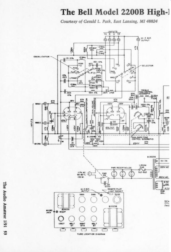
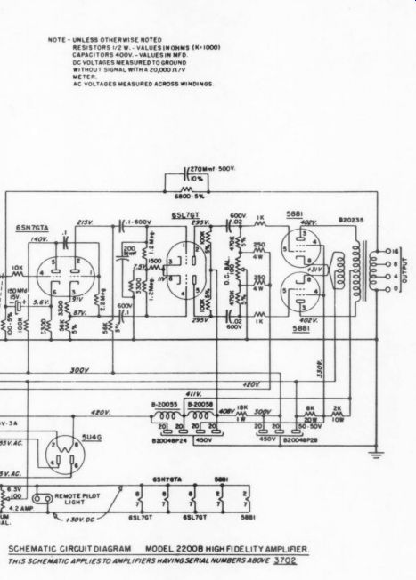
The Bell Model 2200B High-h-Fidelity Amplifier (1953) Courtesy of Gerald L. Park, East Lansing, MI 48824.
NOTE - UNLESS OTHERWISE NOTED RESISTORS I/72 W.- VALUES INOHMS (K*1000) CAPACITORS 400V. - VALUES IN MFD DC VOLTAGES MEASURED TO GROUND WITHOUT SIGNAL WITHA 20,000 N/V METER AC VOLTAGES MEASURED ACROSS WINDINGS 270Mmt S00V.
LETTERS
SHUNT VOLTAGE REGULATORSMY ARTICLE ABOUT shunt voltage regulators ( “Parallel Regulators for Audio," TAA 4/90, p. 39) contains a number of errors and misprints, the most serious of which I wish to correct.
The third paragraph under the heading
"Design Example' and the parts list should refer to Fig. 13, not Fig. 12. This circuit, however, was omitted. Figure 1 shows the missing drawing.
The designation of all electrolytic caps in all figures is reversed and shows in correct polarity. Reversed operation of elcaps causes their destruction.
The first equation under “Practical Circuits ” should read:
Rl = (Vimin - Vo) / | P- ¥ Izmin) The equation for R1 under “Advanced Circuits ” on page 41 should read:
Rl = (Vimin - Vo) / | - * 2c v Iz)
Also, the first formula on page 42 should be written:
I - (Vo oe Vz) / Rg
I apologize for any inconvenience caused by the mistakes and invite all readers to correspond with me if they are interested in a correct version of my article.
They should include $2 for postage.
ANDREAS SCHUBERT, Neckarstr. 5 D 1000 Berlin 44 Germany
CORRECTION
It has come to our attention from several readers that serious flaws exist in the Audio Aid in TAA 3/89, pp. 42-44.
Readers are advised against using the suggestions as published. We regret the inconvenience.-ETD
AS MANY TAA readers have already discovered, there are a few relatively serious problems with the voltage regulator featured in the 3/89 “Audio Aids" which should be addressed. I can't try to guess what regulation criterion Mr.
Aho was attempting to achieve with this circuit, as typical operational parameters of a regulator have not been met.
These could include things like line regulation, low dynamic output impedance, good transient response, ripple rejection, and so on. The following points should be considered:
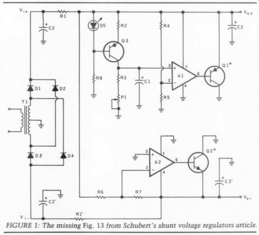
FIG. 1
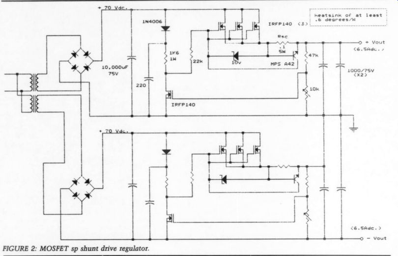
FIGURE 2: MOSFET sp shunt drive regulator.
1. If he has determined that the volt age rails should be 51.4V, then that is what they should remain over the anticipated range of input voltage (presume this to be 105-125Vgps). A 40V trans former is used which we must assume is a full load rating, with primary voltage of 117Vgys. From Schade curves it can be estimated the average output voltage will be about 52V with a ripple compo nent of approximately 9Vp-p at full load or maximum amplifier power. But guess what? The regulator output voltage has now fallen out of regulation, and has, in fact, added more series resistance to the allegedly too high output impedance.
Furthermore, even at low amplifier levels, the thing still falls out of regulation if the line voltage sags more than 3V.
2. As determined earlier, the ripple component is around 9Vp-p at full load.
This means that even when still in regulation, ripple will appear at the regulator output. The ripple will not likely be found at the sources of the output MOSFETs, but will instead appear as periodic noise across the drain-source channel up to the point of output clip ping. One could speculate as to the possible deleterious sonic effects, but in any event, it should not be happening.
Unfortunately, even with adequate voltage headroom, this regulator's rip ple rejection is very poor because the gate of the series pass MOSFET is being modulated by the input supply ripple through the Ry;-error MOSFET voltage divider.
3. Because of the MOSFET's relatively high transconductance, when even small voltage in excess of Vp appears at the gate of the “error ”" MOSFET, a large voltage swing takes place at the pass device's gate. This results in serious overshoot problems. Depending how the "error" MOSFET is biased into conduction, undershoot can also occur, detracting from transient response. This hap pens with this circuit, and as you may expect, this will result in less than ideal wideband dynamic output impedance.
I have tested this circuit using an IRFP140 MOSFET as the pass device and an MTP2N20 as the “error ” device. The dynamic output impedance measured 280mQ up to 15kHz, and then increased markedly with frequency. As could be predicted, by adding an output capacitor the impedance is decreased to a respect able 70mg up to 50kHz. The value of the capacitor is not as important as its high frequency impedance characteristics.
This leads to another problem mentioned in point 5.
4. This regulator does not use a volt age reference, but instead relies on a MOSFET's gate threshold voltage. This is not necessarily a bad thing, but the Vry of a MOSFET is temperature de pendent. Because the feedback voltage divider is about a 14:1 ratio, for each degree of temperature rise, the 6mV change in Vg results in an 84mV change in output voltage. At 4A of output the “error ” MOSFET is sinking more current, and dissipating more power.
In fact, as shown in the original drawing by Mr. Aho, in TAA 3/89, it would be dissipating 0.5W. This will result in a temperature rise of 40° and an output voltage shift of 4V. If a higher input volt age is used for proper regulator operation (say 70V DC), the power dissipation will be substantially more, and the MOSFET eventually would fail without a heat sink, as its junction temperature would be in excess of 190°. Using a heatsink of at least 20k/W, the larger the better, will remedy this. Also because Vg at full load is about a volt higher than at no load, full load output voltage will decrease, adding to the apparent output impedance.
5. Mr. Borbely comments he would recommend using some capacitors at the output. This will, of course, improve transient response and dynamic output impedance, but some readers may not be aware of the potential pitfalls and possible surprises in store if this is done without caution. Anyone not familiar with the mechanism of second break down in bipolar transistors or interpreting SOA (safe operating area) data related to bipolars and MOSFETs should not experiment recklessly with capacitive loads, especially at voltages greater than 50V DC.
It can really put a damper on your inventive mood when you have to pick parts of a TO-220 case out of your face after your 400V preamp regulator explodes on power up into a restrictive load. If an eager hobbyist adds the traditional capacitor bank (of 100 times the theoretically required value) to the Aho regulator, two things will happen. On power up due to the capacitors' reactive nature, the output current will lead the voltage, causing charge current to be limited only by the total of all series resistances including MOSFET channel resistance and capacitor ESR. This will, of course, result in the instantaneous failure of the pass device.
Also, while the gate is held high by resistor Rg,;, the source will be at a considerably lower voltage, likely in excess of the absolute maximum Vi specification. This isn't as much fun to watch, but the MOSFET will be destroyed. It is easy to design current limiting circuits for series pass devices, which as long as they are contained in the feedback loop, do not affect output impedance.
Recommendations:
1. Use high enough input voltage to avoid regulation dropout. In this case, a transformer secondary of about 55V would have been ideal.
2. If really low impedance is important to you, use a monolithic three terminal device configured with a differential voltage limiting pre-regulator. The Linear Technologies LT1038 can output 10A with an output impedance of 3.5 12 m-Ohm (I measured it) across the audio bandwidth with a tiny value of output capacitance. Bear in mind the pre-regulator will dissipate a lot of power. (If you don't know what the input decoupling capacitor is for, I suggest you read some basic voltage regulator handbooks.) UA723 regulators can be configured for high voltage use too and can provide superb performance with adequate pass devices.
Voltage regulator data books will show how these circuits can be used at high currents and voltages and are the best place to start when seeking applications information. I recommend the out of-print Fairchild Regulation Handbook for using the 723.
3. If you must use large output capacitors, add current limiting circuits to avoid failures. Figure 2 shows a typical current limiting circuit which will en sure the pass device's SOA is never exceeded. The resistor Ry is chosen to limit current at a figure above the anticipated maximum output requirement and below the pass device's limit. For high currents and voltages, pass devices are simply paralleled to reduce individual drain currents to safe values. Be sure to clamp the gate to the source with a zener diode of appropriate value.
4. If you make a bipolar regulator using MOSFETs, use only N-channel types. They have a much lower Rp than P-channels and are more rugged.
You will need isolated secondary windings to do this (Fig. 2). The duplicate supplies are then stacked in series to develop the bipolar voltage.
Let's face it, if high power voltage regulators were simple and efficient and cheap, all high-end amplifiers would have regulated output stages instead of regulated voltage amp and driver stages only.
LLoyD S. FLEMMING, Grimsby, Ontario, Canada L3M 1P6
Edward Aho replies:
I must admit, I was pleasantly surprised and delighted to see my letter in 'Audio Aids."' To be published in your quality publication is quite a feather in my cap.
However, I was beginning to wonder if I was the only person concerned about regulating power supplies for power amps. I thank you for your shared concern, and I must report that since publication I have had several calls from readers who also share this concern.
I thank Mr. Flemming for his feedback and for taking the time to analyze and modify my design. I must say, though, we could learn more from Mr. Flemming if he would share his knowledge of the 'pitfalls and possible surprises' in selecting both input and output capacitors. Simply directing us to read out-of date handbooks is not very enlightening.
Most of us have enough trouble finding components; not all of us are engineers who have access to distributors of such products.
I wish to take this opportunity to try to vindicate myself. The design I pro posed was meant to facilitate the components (transformer, caps) that Mr. Borbely had suggested for his design. 1 was trying to provide a means of regulating the power supply without having to buy a lot of new components, and so this was the criterion my design followed. I did use output caps in my de sign, but I inadvertently left them off the schematic. I think everyone caught that obvious error.
The most serious problem associated with this design is its inability to regu late at or near full load. Even more troublesome, a 40V transformer is not capable (without a little creative thought) of delivering the power Mr.
Borbely's 100W designs demand. How ever, I felt the people who had bought these transformers needed to have some kind of regulation. This design will achieve higher performance than the simple capacitor bank, and in fact operates quite nicely.
In the mathematical analysis of Mr Flemming's modifications, I would like to point out a couple areas which may require further investigation, as well as a caution sign.
la. If we use the suggested “ideal ” transformer secondary voltage of 55V, we may see some serious trouble at the storage capacitors which are rated at 75V. I personally would not like to test the failure mode of a capacitor of that size and energy potential. To elaborate mathematically:
+ Vin = 55Vpms (1 + 10%) x sqrt2 85.6V
This (85.6V) would indicate we need to invest even more money to buy caps with higher voltage ratings.
1b. The second problem with this transformer is its cause for inefficiency.
Mr. Flemming's schematic indicates 70V at the input caps, and though it's not shown, we can assume the voltage at the output is the 51.4V I used. Since + Vj can be as much as 85.6V, the 70V must have come from 117V AC line voltage and the use of Shade curves.
This will cause the pass devices to dissipate (P, = (70V --51.4V) x 6.5A) 120.9W. I suggest a good heatsink. I am also interested to learn what Mr. Flemming used for Rg and R; when using the Shade curves.
2. It is not good practice to put a high impedance at the gate of a FET, as has been done here with the 22k resistor.
The IRFP140's gate capacitance is about 1,500pF in this application; that capacitance, three times multiplied by the 22k resistor, yields an RC time constant of about 99S. This will drastically reduce the rise and fall times of these devices, thus adversely affecting the transient response of this power supply. I would hope this is a typo, and that the value should have been 2202.
3. It was suggested that since Rg is within the loop, its resistance would not affect the output impedance. I do not agree. Any series resistance, whether in side or outside the loop, will affect the output impedance. (What about those Shade curves, don't they take this series resistance into account?) When the pass FETs are turned on to re-energize the output caps, the Rg (on) of the FETs as well as any other series resistance makes up an RC time constant with the out put caps. Consequently, our dynamic impedance is affected.
Implementation of the three FETs in a parallel configuration will enhance the output impedance by paralleling their series resistance. Individually their Rg (on) is 0.1622 (Rpg(on) = 0.077 x 2.1), and in parallel the combined Ry (on) is 0.0549, about half the value of Rye. I would say Rg. could play a major role in the dynamic impedance if not properly accounted for.
The FETs shown in the modified schematic happen to have the lowest Rg (on) of a FET in that package, and I think this was done by some design criteria Mr. Flemming was trying to meet. | know the intent wasn't to achieve low regulator dropout-we have plenty of headroom with the new transformer, so they must have been chosen for low out put impedance.
4. Mr. Flemming has me a bit confused. First he tells us the loop gain is high enough to cancel any effects of the series resistance within the loop, then he tells us the loop's gain is not high enough to correct for any disturbance which the pass device's gate might see.
I will do a little more guesswork since he didn't provide us with detailed information on his modifications. The 220uF cap and diode seem to have been added to filter the input ripple from the pass device's gate. This regulator's gain should be high enough to correct for any low-frequency modulation at the pass FET's gate. However, if the 40V trans former is used, this scheme would help keep the regulator from falling out of regulation, to a point, by adding storage at the gate of the pass FET.
5. I wish to ask where this 'traditional capacitor bank of 100 times the theoretically required value' came from! If there were any theory used, it would not only be impractical but absurd to overrate by 100 times. I would be sorely disappointed if this approach were taken with any regulated power supply.
6. I wish to clarify two points:
a. While manufacturers provide SOA curves for both transistors and FETs, they have entirely different meanings.
They define a transistor's secondary breakdown limits. FETs do not have a secondary breakdown. In fact, these curves are somewhat useless since they apply only to pulses at 25°C. The SOA can be calculated directly from the transient thermal impedance data the manufacturer provides.
b. P-channel FETs are just as rugged as N-channels, and the P-channels also come in low Rpg (on) values. They just cost a bit more. If the design can benefit from using P-channel FETs, I for one will certainly use them.
I thank Mr. Flemming for his interest in this voltage regulator.
WRONG WORD
MY "AUDIO AIDS" article in Audio Amateur 2/90 (p. 60) contains an error. The top of column three, line four, should say uncompensated TL0O70, not uncompromising.
DARCY E. STAGGS, Orange, CA 92669
RKV CAR AMP CORRECTIONS
A FEW ERRORS appeared in my published reply to Mr. Endicott's letter (TAA 4/90, p. 56). First, a ground symbol is missing from Fig. 1. The common junction of R3, D2, D3, C4, C6, and C7 should be grounded. Second, the schematic in Fig. 1 is wrongly attributed to TAA. The schematic was taken from an article written by Richard J. Kaufman in the May 1989 issue of Audio (p. 51). The corrected schematic was published in the July 1989 issue of Audio (p. 6). Finally, the caption for Fig. 2 does not make any sense. It should read 'Power supply block diagram."
RANDOLPH K. VIKAN, Seattle, WA 98155
MISSING PARTS LIST
I CONGRATULATE YOU for another nice looking layout of my article (TAA 4/90, p. 18). The detail you get in the printed matter is very good. The small text under Fig. 9 comes out very well. There is an unfortunate omission of the parts list for this figure, however (Table 1). Also, the text at the end that refers to Table 5 should say Table 4 and microamps is used incorrectly for milliamps at the bottom of column one and the top of column three on page 27.
Bill CHATER, Rancho Palos Verdes, CA 90274
--------------
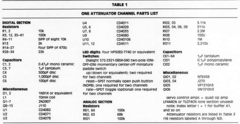
TABLE 1
ONE ATTENUATOR CHANNEL PARTS LIST
DIGITAL SECTION
Resistors R1, 2 R3, 12, 35-41 R4-11 R13 R14-27 R28-34 Capacitors 1,2 10k 100k SIPP of eight 10k 2k four SIPP of 4700 22k
0.47uF mono ceramic C3, 7 1uF tantalum ca 500pF disc ot) 1,000pF disc Cé 100pF disc Miscellaneous D1, 2 1N914 or equivalent 1 10mH coil Q1-7 2N2907 Q8-15 J110 U1 CD4082 u2 CD4071 u3 CD4078 ua CDa011 us, 6 CD4029 uz, 8 CD4035 U9 CD4060 u10 CD40106 U11, 12 CDas11 LED digits: four HP5082-7740 or equivalent
Switches:
Dialight 572-2321-0804-040 two-pole (ON) OFF-(ON) momentary center-off miniature paddle switch up/down (or equivalent); two required for two channels reset-SPST normally open push button (NOPB); one required for two channels rate-SPDT toggle (optional) one required for two channels ANALOG SECTION
Resistors R61, 64 R62, 63 RIO? RiO2, 05 RiO3, 04, 06, 09 RiO7 RiO8 R10 R311 Capacitors C61-64 Cio Cio2 5.11K 5110 2.2m 1000 mM 2,2100 1uF tantalum
0.14F polypropylene 1uF mono ceramic
Miscellaneous
Qi01, 02 Qi03, 04 Qios Qio6 NTEA458 J270 VP1310n3 VN1310n3 servo control amps = quad op amp LF444CN or TL074CN (one section unused) note: index letter i = 1 for buffer A1, and so on Attenuator resistors are listed in Table 3 (16 resistors labeled A through N2).
-----------------
CD CAVEATS
TAA's 2/90 ISSUE contained several interesting articles, and one of particular interest to me. I found Paul Marchese's "High Performance Analog for CD Players ” to be a good introduction to FDNR filters. While the potential benefit from a steeper slope/high-order filter is obvious in theory, I wonder about the affects of a large number of op amps and passive components in the signal path.
To his credit, Mr. Marchese used active and passive components of the highest quality. But I take issue with his concept that if the active GIC filters are not in the series signal path, this minimizes the demands on the op amps. Power supply circuits are not in the series signal path either, but have large effects on signal quality.
Climbing down off my soapbox for a moment, I wholeheartedly agree with his choice of Analog Devices' 846 for the current-to-voltage conversion from the DAC. This is the best sounding op amp for this function available. The device uses current, rather than voltage, for the feedback signal. The inverting input allows open-loop impedance in this topology. The amp is not stable with a capacitor in the feedback loop due to the use of a current, instead of voltage, feed back signal. I have been using these op amps in my CD player for over a year and think they produce truly outstanding sound. I know we will be hearing more about this wonderful op amp.
A couple of caveats are in order. The FDNR filter uses very high impedances as indicated by the 470pF coupling capacitor C1. A CD player is, electrically, a very noisy environment, due to the close proximity of the high speed digital circuitry. Stray digital signals coupled into your analog circuitry can undo the effectiveness of filter circuits which look great on paper. Building a shielded box for analog circuits may be in order. I speak from personal experience using high impedance analog circuitry near digital circuits in both audio and telecom.
Also, the parts list calls for 1uF stacked film capacitors for local power supply decoupling. A 1uF capacitor probably does not have high frequency characteristics good enough to provide quality high frequency decoupling for a fast op amp like the 450MHz gain-band width product AD 846. Since the board is remote from the power supply regulators, I would recommend 220uF Panasonic HFU series electrolytics, by passed with 0.047uF polypropylene or polystyrene film and foil caps. The REL CAP RT series polystyrenes from Precision Audio are the best I have found for low ESR. They sound much better than other polypropylene and polystyrenes I have used in the filter after the DAC in CD players.
I thank Mr. Marchese for an excellent article. I look forward to more articles from him and would love to see an extensive list of references for filter design, the FDNR type in particular.
FRED DIECKMANN, Dallas, TX 75231
Paul Marchese replies:
One thing I find consistent with books on electronic filtering: their introductions are all different. By far the best book on this subject is Filtering in the Time and Frequency Domains, by Her man Blinchikoff and Anatol Zverev (Robert Krieger Publishing Co., 1987).
This book is the complement to Zverev's Handbook of Filter Synthesis (Wiley, 1967), which has extensive tables for the passive circuit realizations. (I was fortunate to be Dr. Blinchikoff's student a few years back.) As for FDNR type filters, I have never come across a good paper on the basics, therefore I worked out all the transformations myself. Many excellent papers, however, treat the non-ideal effects of the components, sensitivities and comparisons and so forth. (See references.)
Reference 1 is a partial answer to your disagreement on the effect of series and shunt components. The oscillation problem was one example I used to show the advantage of this topology. Another ex ample is classical sensitivity analysis.
Leapfrog circuits have a lower sensitivity than the equivalent general impedance converter (GIC) circuits.
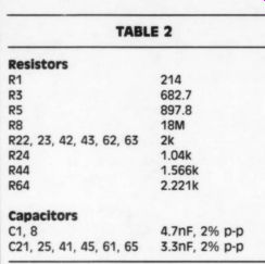
TABLE 2
The open loop gain of an op amp, and, to a lesser degree, the gain bandwidth product (GBWP), are parameters that typically have a wide tolerance (+ 25%).
It can be shown' that if the GBWP's are similar (matched, ideally), the finite gain errors have less effect in GIC type filters than the equivalent leapfrog ones.
This advantage is well hidden in the circuit topology. I agree with you that in most cases (a simple RC network for ex ample) the series and shunt components are equally important.
I was forewarned by Walt Jung about the pickup and generation of noise from the low value of the capacitor and high value resistors. Although I haven't had any problems with my player, the potential is there. I rescaled the filter to be less noise-susceptible and to reduce the generated thermal noise (Table 2). I have not built or modeled this new circuit.
One item to watch is the output level of the GIC op amps with respect to the input. (They should be equal to, or less than, the input level.) The recommended bypassing by Ana log Devices on the AD846 is 2.2uF electrolytic and 0.1uF ceramic. I have not conducted any experiments to evaluate the different bypass capacitors. Your suggestion is well taken.
REFERENCES
1. Bruton, L.T. and K. Ramakrishna, 'On the High Frequency Limitation of Active Lad der Networks."
2. Burton, L.T. and D. Treleaven, “Active Filter Design Using General Impedance Converters,"' EDN 2/5/73.
3. Antoniou, A. and K.S. Naidu, “Modeling of a Gyrator Circuit,' IEEE Circuits &) Systems, August 1975.
4. Ramakrishna, K., 'Noise Minimization in RC Active Filters Using GICs,"' Circuit Theory and Application, Vol. 6, 1978.
5. Ramakrishna, K., 'Effect of Amplifier Imperfections on Active Networks, ” IEEE Circuits & Systems, November 1978.
6. Bruton, L.T. and D.H. Treleaven, “Elec trical Noise in Low Pass FDNR Filters, ” IEEE Circuit Theory, March 1973.
7. Skritek, P., 'Comparison of Overload and Noise Characteristics of FDNR Circuits,' IEEE Circuits & Systems, July 1983.
CHATER MOS MODS
IF YOU ARE building the “Mostly MOS Preamp ” (TAA 1/90 and 2/90), please note the following correction items and suggestions.
1. As mentioned in Part I of the article, certain of the small-value capacitors in the line driver circuit may have to be experimentally determined in order to provide the most nearly flat frequency response. (Refer to the curves of Figs. 15 and 16 in Part I.) Capacitors C303 and 308 are two such items. The suggested values in the parts list are 39pF for C303 and 36pF for C308. Since stray capacitance may be a little different with each assembly, you may find other values for these capacitors which give flatter response in your tests. The schematic (Fig. 13) shows 68pF for C303, a value suited
to the prototype card. Feel free to make use of any value for C303 (and C308) in this range of capacitors that leads you to a satisfactory response.
2. Capacitor C315 is given as 470pF polypropylene in the parts list, but is 300pF in the circuit drawing, Fig. 13.
This is another example of the difference between the prototype and the completed circuit. I suggest you use the 470pF value for C315 and correct the de tail of Fig. 13 to agree with this. This capacitor adjusts the loop stability of the circuit and should not need tailoring.
3. The capacitors in the signal path of all boards in the design are polypropylene, with two exceptions. Small capacitors, below 100pF, are not available in polypropylene from the Digi-Key catalog, so I chose to use disc capacitors in these cases. (These are capacitors C1, 201, 206, 303, 304, 306, and 308.) You may prefer to substitute glass or mica dielectric for these capacitors or polypropylene if you can find them in these smaller sizes.
Most glass or mica types of the capacitance required can be fitted into the card layout by using the vertical 'Japanese cordwood' style of packing, if necessary.
The other exception mentioned is that of C217, 301, and 302. I have listed these three capacitors as monolithic ceramic non-polar units. If you prefer to replace these units with polypropylene, you can relocate C217 (a 2.2uF unit) along with resistor R225 onto the switch assembly S§5, instead of mounting these parts on the card. In this way there will be room for the larger poly unit without necessitating a change in the board. If you do this, be careful that the wiring run from the board to C217 does not have a chance to short to ground. Such a short can cause damage to the card if the servo amp A201 tries to force the node at the junction of R223 and 224 to a slightly non-zero volt age, as it would if A201 has a little off set. This action can lead to a large current flow in R223 or 224 and destroy a resistor. (I know-it happened to me.
C217 protects against this problem if accidental shorts occur outside the preamp in the Tape 1, Tape 2 lines.) If you prefer to substitute polypropylene units for C301 and 302, these capacitors, along with their associated resistors, R303 and 304, can be relocated off the card onto the phase switches S1.
Since this slight wiring change might | alter the total stray capacitance to ground of these parts, a subsequent readjustment of the high-frequency trimming capacitor C303 or 308 might be needed as mentioned in item 1.
4. It has been observed ('MOS Pre amp, “ TAA 2/90, p. 5) that have some times incorrectly drawn the symbol for the p-channel MOSFET in Figs. 6, 7, and 18. Refer to the corrections mentioned in this letter by Mark Johnson if you wish to correct your copy of these circuit diagrams.
5. Part I of the preamp article has an incorrect title in Fig. 17. This spectrum of the line amp output was done at a gain setting of 18dB. (There is no 10dB gain setting-sorry.)
6. If you are using the small drawings of the pin-outs of the TO-92 transistors (see between Figs. 10a and 10B of the article), please note that the caption for the upper of the icons should be "NTE458 or J270."
WILLIAM CHATER, Rancho Palos Verdes, CA 90274
JUST LOOKING
B&K Precision has introduced a 2MHz function generator featuring a four-digit display generator, which provides a full range of capabilities, including variable duty cycle, an accurate signal source for sinc, triangle, and square waveforms, plus TTL and CMOS pulse signals The Model 3011B covers from 0.2Hz to 2MHz in seven ranges. Special features include coarse- and fine-frequency controls, a separate TTL and CMOS pulse output and external sweep/source capability. Duty cycle is continuously variable from 1:1 to 10:1, and when inverted from 1:1 to 1:10.
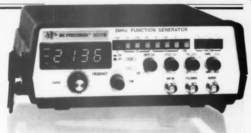
The built-in frequency counter with 10ppm time base permits precision frequency settings, previously unattainable without external test equipment. The bright LED display gives four-digit resolution and the fine-frequency control enhances settability.
For engineering applications, a switchable variable-DC offset introduces a DC signal on the generator output. This capability is useful for matching the DC voltage at the signal input point, to pre vent changes when the test signal is applied, and for evaluating effects of DC bias on AC circuits.
Sinc wave distortion is less than 1%, with square wave symmetry of better than 98% at 100kHz and triangle wave linearity at 98%. Output level is continuously adjustable from 0 to -20dB.
A 20dB step attenuator extends the range from 0 to -40dB.
The model 3011B costs $249. For more information, contact B&K Precision, Division of Maxtec International Corp., 6470 W. Cortland St., Chicago, IL 60635, or call (312) 889-9087.
Precision Monolithics, Inc. has released the industry's first instrumentation amplifier and low-noise amplifier SPICE models. These models are available on the newest version of PMI Spice (Release B), a free diskette containing PMI's entire SPICE macromodel library.
Previously, designers had to create their own macromodels to simulate instrumentation and low-noise amplifiers.
The OP-177 and OP-77 op amp models are the first to enable complete noise analysis simulations. These models accurately simulate the broadband noise and the 1/f noise for both voltage and current noise. Designers can easily simulate the total output noise and equivalent input noise of their circuits over the entire frequency range.
The latest version of PMI Spice also includes the industry's first SPICE models for the AMP-01 and AMP-02 instrumentation amplifiers. These models characterize the actual device, including their functional attributes, such as the sense and reference terminals and the gain setting resistors.
All PMI Spice models offer AC and transient response accuracy. Because the models have a high order of poles and zeros to shape their frequency responses, they closely reflect the actual devices' responses, allowing for higher confidence in circuit simulation accuracy.
The free 5% " PC-compatible diskette contains 54 complete model net-lists of PMI's operational amplifiers, instrumentation amplifiers and matched transistor pairs. To receive a complimentary copy, please call (408) 562-7470. For technical information regarding the PMI Spice models, call (408) 562-7302.
Coda Technologies has introduced an FET preamp, the Model 01. A single rack height unit, its features include: five line level, one phono input with switchable gain and loading; optional board to by pass the phono stage; two buffered re cording loops which operate independent of the source selector; and conventional and balanced outputs with switchable USA/European phasing. The chassis' structural parts are machined aluminum. The Model 01's price is $2,500. For further information contact Coda Technologies, Inc., 9233 Wausau Way, Sacramento, CA 95826, (916) 366-6420.
Carver Professional has debuted two additions to its line of magnetic field power amplifiers. The 45-1b. PT-2400 produces 1,200W per channel into 4 ohm, and 3,000W bridged into 4, 20Hz-20kHz. The PT 1800 weighs only 42 pounds, and is rated at 900W per channel into 4 ohm (2,200W bridged into 4 ohm , 20Hz-20kHz). Each is just 12%" deep.
The PT-2400 and PT-1800 are fully modular dual monaural designs from power switch to AC line cord, and are highly efficient (50% input to output).
Features include positive locking detachable dual AC line cords, rugged, quiet, 100CFM cooling system, a com pressed circuit for excessive long-term frequency signals, clipping eliminator circuit, four protection circuits, and re mote sequential power on/off feature.
For information call (206) 775-1202.
FM Atlas and Station Directory
by Bruce F. Elving shows on maps and directories 6,750 FM stations, both public and commercial, as well as low-power FM translators and boosters of the US, Canada, and Mexico. Programming trends, such as the loss of music stations in many cities, are also discussed, as is the demise of Canada's CKO FM news network.
The 192-page, 13th edition also lists stations with an FM-SC Subcarrier. It gives music formats and shows which stations are broadcasting in stereo and which are monophonic. The directory sells for $12 including shipping from FM Atlas, Box 24, Adolph, MN 55701-0024.
EEE Ss Soundings-ElectroTec has announced its appointment as North American import agents and distributors for Minim ambisonic surround-sound decoders and processors for the consumer hi-fi and professional recording markets. The catalog numbers several hundred and is exclusively ambisonic.
Minim currently manufactures two decoders. The AD10 is a high-specification, full-feature system including Loud speaker Aspect Ratio control, Focus, Position (you can effectively move your self forward or backward in the sound field for more/less audience/ambience), and Stereo Enhance for normal stereo recordings (variable from central mono image to a complete surround picture).
The AD10 sells for $595, the AD7 De coder for $325. For more information, contact Nigel Branwell, Soundings ElectroTec Inc., PO Box 10004, Wins low, WA 98110, (206) 842-7128, FAX (206) 842-5026.
We Enjoy Hearing From You.
Audio Amateur is a place for readers to meet and discuss ideas, projects, and challenges. When you write, please include a self-ad dressed envelope, with stamp attached with a clip, if you expect a reply. If the author lives outside of the US, please include two International Postal Reply coupons (available at your post office) in stead of stamps. Because of space limitations, we reserve the right to edit all letters. Although we read and note all letters, only those of general interest are selected for publication. When responding to an article, please cite the name of the magazine, article, letter, department, and the page number. Address all correspondence to the Letters Department, Audio Amateur, PO Box 576, Peterborough, NH 03458-0576.
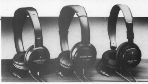
Audio-Technica US has introduced a new line of mid-sized stereophones, designated ATH-M2X, ATH-M3X, and ATH M4X, which are specifically designed for digital sources such as compact disk and digital audio tape. These sources, with their wide dynamic range, can drive conventional stereophones to distortion.
These stereophones use 40mm drivers, and the ATH-M4X uses Samarium cobalt magnets to provide extra sensitivity and power-handling capacity. The M2X and M4X are open-back designs, the M3X is a closed-back unit. All three use leatherette ear-pads and have adjustable headbands.
The ATH-M4X sells for $49.95, the M3X for $39.95, and the M2X for $29.95. For more information, contact Audio Technica US, Inc., 1221 Commerce Dr., Stow, OH 44224, (216) 686-2600.
connect terminals on one end. Pushing the end of the terminals opens a slot to receive and hold securely a bare wire or test probe. The other end of the plug terminates in one of several connections.
It is a useful item in any electronics toolbox for field work, for outside broad cast testing, or for experimental or maintenance work.
For more information, contact Connectronics, 652 Glenbrook Rd., Stamford, CT 06906, (203) 324-2889 or (800) 322-2537, FAX (203) 324-7027.
Carver has introduced the DPL-33 and the AV-63, audio/video products that en able you to add home theater surround sound capabilities to your video system.
The DPL-33 is a Dolby Pro Logic decoder and spatial processor with a built-in three-channel amplifier. Added to a stereo system, it creates a five-channel surround-sound home theater with remote control. The amplifier can be used to drive a center channel speaker with 25W and two rear surround-sound speakers with 15W each. The DPL-33 has switch able 20 and 30mS time-delay circuits.
The AV-63 is a three-channel add-on amplifier designed for use with surround sound decoders without built-in amplification. The amplifier is rated at 65W per channel, driven into 82, from 20Hz to 20kHz with no more than 0.5% THD.
The AV-63 has front-panel gain controls and vertical LED power displays for each channel.
The DPL-33 costs $449.95; the AV-63 (available in May) has a suggested retail price of $529.95. For more information, contact Gordon Sell at (201) 509-0097 or Lori Kaufman at (206) 775-1202.
Jung-Childress Audio & Electronics have announced a Philips CD80 upgrade, the JCA&E 8.0 Premium Mod. It is available in complete (C) or transport (T) version.
The latter is for those with DAC processors and does not include analog and some associated power supply upgrades.
The analog amplification system has been replaced with JCA&E-designed proprietary circuits. The player can repro duce the entire dynamic range of orchestral music without any strain, image shifting, or masking of detail.
Selected sections of the digital processing system have been upgraded and all power supplies have been re-evaluated.
Also, many factory-installed features have been retained or enhanced.
The JCA&E 8.0 Premium Mod is avail able installed in a CD80 (C, $2,995; T, $1,495) or as a mod (C, $2,295; T, $795).
For more information, contact JCA&E, PO Box 36141, Towson, MD 21286, (301) 557-6189 or 377-6443, FAX (301) 377-6109.
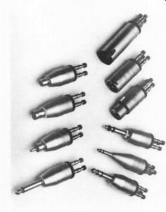
The Director from Audio Control is a speaker switcher and system controller capable of handling two different sources (like a TV and a stereo system) at the same time. It is a full sized unit, and other items in a stereo system, like a compact disk player, can be stacked on top. Since it uses speaker wires and speaker level, it is easy to in stall and can run all speaker systems in the house on one amplifier. The Director contains automatic impedance protection to safeguard the amplifier from problems of connecting too many speakers.
The Director controls up to six zones of speakers. Five are dedicated to one source (like the stereo system). The main zone may be playing the same music or it may be connected to a different source (like the TV), and it has a separate volume control.
The suggested retail price of The Director is $299 and is available at specialty audio stores. For more information, contact Tom Walker or Mark Eshom at Audio Control, 22313 70th Ave. W., Mountlake Terrace, WA 98043, (206) 775-8461, FAX (206) 778 3166, TX 3711409.
Also see: