IN HIS INITIAL building frenzy, the amateur discovers--much to his delight --he can actually put together something that works; does not smoke, spark, or blow up; and sounds better than what he started with. Afterwards, however, he may wish to probe a little deeper and make simple measurements.
The first investment is generally a multimeter, which these days is most often a digital model. This is the mini mum required for even the simplest checking of any electronics project. The next step may be (deep breath here) an oscilloscope, or perhaps an oscillator springs to mind. A good sine wave oscillator is useful for several purposes.
You can use it with a voltmeter to measure frequency response and with a distortion meter to measure distortion.
You can also use it to optimize tape recorder bias and frequency response, to inject a signal into a circuit for trouble shooting purposes, and to perform other functions.
I decided to get one because I was starting a speaker project and wished to measure loudspeaker response and impedance curves. A browse through any large electronics supply catalog will show several wonderful oscillators, distortion meters, and other equipment- unfortunately, at not so wonderful prices. While some inexpensive oscillators have continuously variable frequencies, I prefer switched frequency controls because of their better repeat ability and potentially better precision.
-----------
ABOUT THE AUTHOR: James Lin was a graduate student in physics before switching to medicine. He was an Oncology Fellow at Memorial Sloan-Kettering Cancer Center before moving to Galveston, TX, where he teaches medicine. He has built several electronic kits and projects from Audio Amateur and has written for Speaker Builder.
-----------
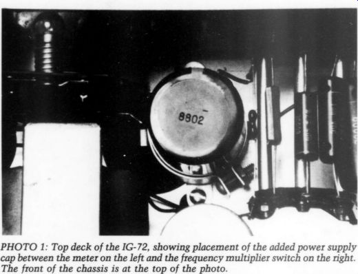
PHOTO 1: Top deck of the IG-72, showing placement of the added power supply cap between the meter on the left and the frequency multiplier switch on the right. The front of the chassis is at the top of the photo.
-------------
A price of $200 to $400 for such an instrument may be inexpensive for the local repair shop, where they are used daily, but is hardly so for the amateur.
Here is where used instruments come in. Tubed oscillators, distortion meters, and other devices from companies such as Heath, or even Hewlett-Packard, are available at reasonable prices. While they may not possess the ultra low distortion and conveniences of modem instruments, neither do they have their prices.
-------------
NOTES:
ALL RESISTORS ARE 1/2 WATT UNLESS MARKED OTHERWISE.
ALL RESISTOR VALUES ARE IN OHMS ' K = 1000, MEG ~ 1,000,000).
ALL CAPACITOR VALUES ARE IN ufd UNLESS MARKED OTHERWISE.
(CO WDICATES VOLTAGE READING.
ALL VOLTAGES ARE DC POSITIVE UNLESS MARKED OTHERWISE.
ALL VOLTAGES ARE MEASURED FROM POINT INDICATED TO CHASSIS GROUND EXCEPT AC VOLTAGES ON POWER TRANSFORMER WINDINGS.
VOLTAGE READINGS TAKEN WITH AN 11 MEGOHM INPUT VTVM.
VOLTAGES MAY VARY 210%.
SCHEMATIC OF THE HEATHKIT® AUDIO GENERATOR MODEL 1G-72
Heath Corporation.
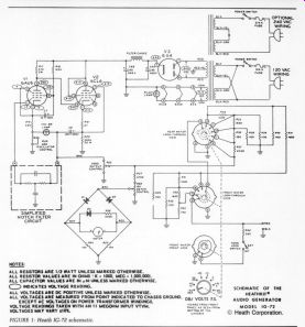
FIGURE 1: Heath IG-72 schematic.
--------------
Checking Under the Hood
After shopping around in a few local electronics stores, I purchased a Heath kit IG-72 sine wave oscillator, which I refurbished. The IG-72 was the predecessor to the solid-state IG-18, which has been the subject of several articles over the years in Audio Amateur, most notably by Reg Williamson (TAA 1/71, p. 7, with corrections in 4/71, p. 13) and Walt Morrey (TAA 4/75, p. 3, with corrections in 1/76, p. 40), along with letters and tips too numerous to list.
The IG-18 includes a square wave generator and continuously variable frequency control lacking in the older model. Lest you think all the advantages lie with the newer design, the basic distortion of the tubed model is at least as low, if not lower, than its solid-state successor, at least in stock form (see the review of the Heathkit IM 5258 THD meter in TAA 2/78, p. 48), and it also has a much bigger, easier to read meter.
The design is delightfully simple, consisting of two tubes, a 6X4 rectifier tube, and a handful of capacitors and resistors (Fig. 1). The frequency-determining network is particularly ingenious, in my opinion, using only five capacitors to cover four frequency ranges, and four pairs of resistors for each decade switch.
An abbreviated manual is still avail able from Heath; it contains the setup and calibration procedure, but omits the construction section. Since it is unlikely any unassembled kits remain, this isn't a loss, except this manual doesn't show the parts' physical lay out-it has no circuit board; everything is hard-wired. However, the circuit is simple enough that you should be able to work it out from the circuit diagram.
Naturally, if you plan to work on this unit, or any used equipment, have the manual on hand before starting.
After Market Mods
The store where I purchased my unit hooked it up to an oscilloscope to con firm it was working. At home, I opened it up to check in more detail. When I tested all the resistors to determine if they were within spec, I encountered my first problem. One resistor on the 10's frequency switch had an open circuit and required replacement.
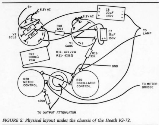
FIGURE 2: Physical layout under the chassis of the Heath IG-72.
I also noted that although Heath had used precision 2% capacitors for the frequency multiplier switch and precision 1% resistors for the 10's decade switch, the 1's frequency switch used ordinary carbon comp resistors. As a money-saving measure, this made sense, since an error at this position was much less critical than at the 10's switch, where a 1% error is comparable to a 10% error at the 1's switch. However, since metal film resistors are reasonably in expensive nowadays, I replaced these resistors with matched metal film units of equivalent value. As long as I was at it, I replaced the three AW carbon comp resistors in the circuit with metal film equivalents, and the 47k 1/2W resistor with a metal oxide equivalent.
Figure 2 shows their location. In some cases, I left component leads long and used them to connect two tube pins together. The resulting circuit is not mechanically identical to the schematic. Specifically, the 47 k-Ohm/2W plate resistor of tube V1 (6AU6) is located at the V2 socket, R17 is connected to pin 9, and so on. R17 is connected to pin 9 of tube V2 (6CL6) in the schematic, but to pin 2 in the layout.
Because the two pins are connected internally, however, the circuits are electrically identical.
Since we are mainly interested in closer tolerance and better stability, any metal film and metal oxide resistors will do. I see no point in using expensive premium resistors such as those in a state-of-the-art preamp. (This POOGE business can be carried too far; I once saw polystyrene bypass caps in a power output indicator.) Next, I turned my attention to the attenuation switch, which also contained carbon comp resistors. Checking the attenuation showed an error below the 1V range. Later, I discovered Carlstrom and Muller's note (TAA 2/78, p. 37), which described an identical problem in the IG-18's attenuator. Their suggested revision replaces R38 with a 910-1 k-Ohm resistor.
Although only one resistor change is required, I implemented it with 4W metal film resistors to replace all resistors with equivalent 1% types. Specifically, I used 412 ohm for R36; 9762 for R38; and 750, 1.13k, 1.65k, and 2.43 k-Ohm values for the remaining resistors. If you do this, remove the switch from the unit to make the process easier. I also replaced output load resistor R42 with a 590 ohm metal film resistor. A UW rating is more than adequate for these resistors, as their power dissipation is minimal.
As I mentioned above, Heath used precision capacitors in the frequency multiplier switch, and a check of these with a capacitance meter showed they were still within 1% of their nominal value. These capacitors are spaced a decade apart except for the smallest one, which is 47pF rather than the expected 50pF. This was done because it was expected that stray capacitance would make up the difference, giving a total of 50pF for the highest range.
In my unit, however, this cap measured only 45pF in circuit, and coupled with a low stray capacitance, resulted in the frequencies on the highest range measuring consistently high using a frequency counter. I therefore replaced it with a 50pF cap, bringing the high range frequencies much closer to what they should be.
Since the change is small, another way to accomplish this is to twist two lengths of solid core wire together and solder them across the 47pF cap. The two wires act as a very small value capacitor (using 18-gauge wire, I got just under 2pF/inch). You can adjust them by gradually cutting them shorter, until you get a total of 50pF measured by a capacitance meter, or if you have a frequency counter, you can adjust for the best frequency match between what the knobs say and what the counter says. Needless to say, if you use the latter method, turn off the generator and disconnect it from the line before trimming back the wire capacitor.
Since old electrolytic capacitors can become leaky, I replaced the ones in the circuit with new caps of equal volt age rating. I kept C17 the same size, but increased the output cap C18 to 47uF/350V to extend the low-frequency response slightly.
One problem reported in the IG-72 is the presence of power supply noise in the output. The power supply consists of a capacitor input followed by a choke/capacitor filter. The DC resistance of the choke in my unit was about 22092, which should make it safe to increase the following capacitor. It was hoped this would decrease power supply noise and increase low-frequency stability. Therefore, I increased the capacitance of the power supply's last stage by adding a 330uF/450V Panasonic capacitor, which I located on the top deck between the meter and the frequency multiplier switch, held in place by a capacitor clamp. To minimize power supply lead lengths, I mounted it with the terminals pointing down in to the large hole, which was already in the chassis (Photo 1). As you can see, it's a tight fit, but it does fit. But, be careful not to let any of the leads short out against the chassis.
At this point, things were looking good. At low frequencies, however, I noticed the meter followed each cycle of oscillation, making it difficult to read. Taking a hint from Reg William son's article on the IG-18 (TAA 1/81, p. 7), I added a 220uF/35V electrolytic cap across the diode bridge to improve meter stability at low frequencies. In placing this capacitor, make sure the polarity is correct: the positive lead of the capacitor should go to the positive meter terminal. Interestingly, the resistor and diode in series across the meter, which Williamson recommends adding to improve meter linearity in the IG-18, is already present in the older model.
Williamson also noted that the meter circuit caused distortion due to the non linear load of the diodes on the oscillator, which he corrected with a emitter follower buffer circuit. This could occur with the IG-72 also, although the larger buffering resistor (4.7 k-Ohm versus 620 ohm) in the older model should make this less of a problem.
However, I suggest the circuit in Fig. 3, adapted from Naim's buffer circuit for the IG-18 (TAA 1/73, p. 28), which you can build on a small piece of perf board and mount close to the output terminals on the underside of the chassis. The original circuit used a 40408 transistor, but any NPN transistor with a V_cbo of 50V or so, such as the widely available 2N5210, will do. Connect the input of the circuit to the top of the attenuator switch, the 160 k-Ohm dropping resistor to 410V, and the output to the ...
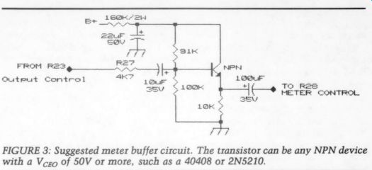
FIGURE 3: Suggested meter buffer circuit. The transistor can be any NPN device
with a Vo of 50V or more, such as a 40408 or 2N5210.
... top of the meter sensitivity pot. With my rather primitive instrumentation, I noted a very slight, but consistent, lowering of THD by 0.01% or so.
I would make one other change if I could find the parts: a continuously variable frequency control. A suggested circuit was published many years ago by D.W. Palomaki (Popular Electronics, December 1970, p. 65). However, it re quires a dual 10 M-OHM pot with a DPST switch (to disconnect it when set to zero), and I haven't been able to locate a source for such a high value. Nor am I optimistic about doing so since transistors generally work with much lower resistances, making demand for a 10 M-OHM anything likely to be very low. (The IG-18, which has a continuously vari able control, uses resistances that are ten times lower, and so works with a 1 M-OHM rheostat at this position.) Finally, the IG-72 has binding post outputs. Have you ever seen a piece of audio equipment with binding post inputs? I haven't. Of course, you could always create a cable with banana plugs or spade lugs at one end and a phono jack at the other, but my experience is that such special pieces tend to wander off just when you need them. On the other hand, I generally have a few spare phono patch cords lying around. There fore, I installed a phono plug output about 1/4 " to the left of the black binding post (to keep it out of the way of the output attenuator control), connecting the center pin to the red binding post.
Washing and Waxing
Before closing it up, I cleaned all the switch contacts with Cramolin. The amount of crud removed by this step was truly impressive, as the contacts changed color from black to copper.
This is more than a cosmetic step, since dirty contacts can measurably in crease distortion.
When I finished, I plugged in the unit and checked all the tube voltages against the manual to make sure everything was up to snuff. Measuring voltages in a live circuit is actually the best indicator of proper tube and circuit function, but requires care, considering the high voltages involved in tube circuits (not that I wouldn't exercise similar pre cautions around a solid-state super-amp that is capable of arc-welding your foot to your tongue). Perform such checking using the old military technique, with the ground lead clipped to the chassis, the probe lead in one hand, and your other hand in your pocket to prevent any unpleasant surprises. To coin a cliche, there are old voltage checkers, and there are bold voltage checkers, but there are no old, bold voltage checkers.
Since everything was satisfactory, I followed the manual's procedure to set up the oscillator and calibrate its meter. Then I closed up the unit. Harmonic distortion, as checked later on a Heath IM 12 distortion meter, was in the 0.23-0.04% range, increasing to 0.08% at 20Hz. These results, however, probably reflect the residual of the THD meter rather than true distortion.
Going 100,000 Miles
In summary, a tubed sine wave oscillator was a worthwhile addition to my test instruments. As a result of my experience, when purchasing a tubed instrument, I recommend the following (a lot of which is common sense and applicable to any used gear):
1. As far as possible, confirm that the unit is in working condition, unless you are specifically purchasing it as is, in which case, be prepared to trouble shoot. This can sometimes be difficult, as a unit with marginal tubes or over heated resistors may still ‘work,’ but not up to original specifications. You may also wish to look inside, especially if the unit was originally built from a kit. One occasionally hears rumors of kits built by first-time builders that look like a bomb went off inside.
2. Be sure a schematic, layout dia gram, and operating manual are avail able for any unit you purchase, especially if the company is no longer in business. Even if it is, you are not guaranteed is has documentation on old gear.
3. Check that the tubes are in good condition, either with a tube tester or preferably in circuit. But be careful! If you are buying from a store, you may wish to have an agreement as to who pays for any tube replacements that may be required.
4. If you are buying a unit as is, check all resistors and capacitors to be sure they are within spec. This is probably a good idea in any case, but if you are like me, you are probably lazy and not inclined to do such a thing unless something is obviously wrong.
Older units often contain carbon comp resistors, however, which are notorious for drifting out of spec due to thermal aging. Old electrolytic capacitors may have leaked electrolyte and you should view them with suspicion.
Replace any out of spec components and any that look or smell burned, discolored, or otherwise abused with components of equal value and equal or higher voltage and power rating before you plug it in and turn it on.
5. Finally, clean all switches, rheostats, connectors, and other devices with a SMALL amount of Cramolin (available from Old Colony Sound Labs and other sources) or another good con tact cleaner. Some people believe that if a little cleaner is good, a lot is better, which is not so. Be wary of using Tweek, as I have read unconfirmed re ports that it may damage some insulating materials.
This won't guarantee that you won't come up with a lemon, but remember, this far into the solid-state era, unreliable and dead tube units are most likely occupying landfills. Those tubed units that are still around probably worked and worked well for many years, and with some care, should be able to work well for many more.
SUPPLIERS
Digi-Key 701 Brooks Ave. South PO Box 677 Thief River Falls, MN 56701-0677
1/4W metal film resistors, Panasonic electrolytic capacitors, transistors
Mouser Electronics 2401 Hwy. 287 North Mansfield, TX 76063 (800) 346-6873
metal film and metal oxide resistors, electrolytic capacitors, transistors
++++++++++++++++
Also see: