- Intro
- EDITORIAL--Get Going
- AUDIO AIDS
- SHOWCASE
- BOOK REVIEWS
- JUST LOOKING
- LETTERS
INTRO
In the second installment in his series on feedforward error cancellation , Ron Bauman discusses the applications and measurements involved. He has built another version of his original line amplifier, only this time using better passive components. For those of you who missed it, Ron's first article on the principles and design appeared in TAA 4/89.
Modifying units is a favorite past time of amateurs. James Lin, in need of a reasonably priced sine wave generator with switched frequency control, decided to upgrade his tips for those purchasing used gear.
Ron Sawyer explains proper grounding techniques and why some common methods will pro duce noise spikes.
Next in the lineup, Joseph O'Connell writes about designing stepped attenuators for Borbely's suggested balanced audio amp designs.
In the final featured article this month, John Jackson proposes a cable that is phase coherent up to 100kHz. His construction process Heath's IG-72.
JUST LOOKING
Sescom has announced Audio-Tran, a development in audio transformer technology. Audio transformers used in professional audio applications are favorites in field and studio applications, but have suffered by comparison to developments in electronic circuitry. They exhibit low frequency, high-level distortion.
Audio-Tran can compete with the good features of electronic circuitry combined with features of audio transformers.
These new modules have specially de signed transformers with electronic circuitry to give high power levels with ultra-low distortion across the audio band. The distortion is less than 0.005% from 20Hz to over 50kHz.
Two types of modules are available: the AT-O series of output types and the AT-I series of input types, both micro phone and line units. These units are designed for OEM requirements only.
For more information, contact Frank J. Miller, Sescom, Inc., 2100 Ward Dr., Henderson, NV 89015, (702) 565 3400, FAX (702) 565-4828.
The OP-177 from Precision Monolithics is an ultra-precision operational amplifier. Its offset voltage is 10uV MAX at room temperature and 20uV MAX over the full military temperature range. The ultra-low Vpg of the OP-177 combines with its offset voltage drift (TCV) of 0.1uV/°C MAX to eliminate the need for external V,s adjustment and increases system accuracy over temperature.
The amp's loop gain of 12V/uV is maintained over the full + 10V output range. The OP-177 displays CMRR of 130dB MIN, PSRR of 120dB MIN, and maximum supply current of 2mA.
This low-noise bipolar input op amp is also a cost-effective alternative to chopper-stabilized amps. It provides chopper-type performance without high noise, low-frequency chopper spikes, large physical size, limited common mode input voltage range, and bulky external storage capacitors.
The OP-177 is offered in the -55°C to 125°C military and the -40°C to 85°C extended industrial temperature ranges. It is also available in 8-pin ceramic and epoxy DIPs, as well as the space-saving 8-pin Small-Outline and the Leadless Chip Carrier packages.
For more information, contact Precision Monolithics Inc., PO Box 612410, San Jose, CA 95161-9985.
AudioSource has introduced the SS One ($249) and SS Two ($299) systems. These packages include a surround sound processor, two LS Ten/A loudspeakers, 100 feet of 18-gauge speaker wire, and easy to-understand instructions.
The SS One's sound processor has a built-in 30W/channel amplifier and three effect models. Matrix synthesizes stereo sound from mono sources, Hall simulates a concert hall, and Dolby Sur round provides the Dolby sound encoded on most of today's program material.
A variable delay circuit (10-30mS) lets you alter the size of your listening area while in Hall mode or deepen the 3-D effect of Dolby-encoded sound. You can also add ‘presence ’ to the low and high frequencies by adjusting the dual boost controls. A fader control provides front to-rear balancing, and the volume control automatically adjusts the output of the front and rear loudspeakers simultaneously. The SS Two includes remote control.
For more information, contact Audio of Analog Devices' IC amplifiers is avail able from the company. The advanced modeling techniques used allow as many poles and zeroes as are needed to shape a model's frequency response accurately to conform to the device. For 26 of the devices, models include voltage and cur rent noise; this allows designers to predict system noise performance as part of the SPICE simulation. The library also includes models of two instrumentation amplifiers.
For more information, contact:
Analog Devices Literature Center, 70 Shawmut Rd., Canton, MA 02021.
KAB Electro-Acoustics has announced the Gliding Platter component kit, an upgrade for the Nitty-Gritty model 1 and Record Doctor LP cleaning machines.
With these machines, the LP is coated with a cleaning solution and then manually rotated across a vacuum slot. The kit's pancake rolling needle bearing and aligning spacer install beneath the existing machine platter without tools or modifications.
The Gliding Platter sells for $14. A free brochure is also available. For more in formation, contact KAB Electro-Acoustics, PO Box 2922, Plainfield, NJ 07062 2922.
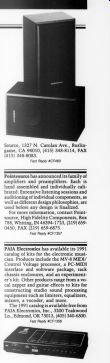
Source, 1327 N. Carolan Ave., Burlingame, CA 94010, (415) 348-8114, FAX (415) 348-8083.
Point-source has announced its family of amplifiers and preamplifiers. Each is hand assembled and individually calibrated. Extensive listening sessions and auditioning of individual components, as well as different design philosophies, are used before any design is finalized.
For more information, contact Point source, High Fidelity Components, Box 788, Whiting, IN 46394-1723, (219) 659-0450, FAX (219) 659-6875.
PAIA Electronics has available its 1991 catalog of kits for the electronic musician. Products include the MV-8 MIDI/ Control Voltage processor, a PC-MIDI interface and software package, rack chassis enclosures, and an experimenter's kit. Other products range from a vo cal zapper and guitar effects to kits for constructing studio sound processing equipment such as limiters, equalizers, mixers, a vocoder, and more.
The 1991 catalog is available free from PAIA Electronics, Inc., 3200 Teakwood Ln., Edmond, OK 73013, (405) 340-6300.
Audio Synthesis has available its ‘AMP-02 and Audiophile Parts Catalog, ’ designed for audio professionals and enthusiasts to help source components that may be difficult to obtain. To be selected for inclusion, the components must sonically improve on any existing alternative, within reasonable price boundaries.
Catalog and air postage are $5. For more information, contact Audio Synthesis, 99 Lapwing Lane, Manchester, M20 OUT, England, +4461 434 0126.
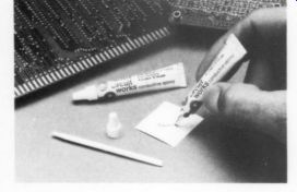
Planned Projects has introduced the 2400 Circuit Works Conductive Epoxy Kit for quick, solderless connection and conductive bonding applications in electronic design, prototype, and repair. Other applications include solderless surface mount connections, circuit board trace repair, die attach, static discharge drains, shield bonding, and grounding.
The conductor is a two-part silver epoxy featuring electrical conductivity with resistivity typically 0.0012/cm and 10-minute room-temperature curing.
The material approaches maximum bond strength in 24 hours. Bonding performance can be accelerated by mild heat curing at less than 100°C.
The kit provides 12 grams of silver epoxy in two tubes, instructions, and a reusable stir applicator. The epoxy, mixed at a 1:1 ratio, resists most sol vents and bonds aggressively to a wide variety of materials including solder alloys, aluminum, alumina, glass, Mylar, piezo films, copper, and epoxy laminate, as well as many plastics.
The kit sells for $14.95. For more in formation, contact Planned Products, 303 Potrero St., Suite 53, Santa Cruz, CA 95060, (408) 459-8088, FAX (408) 459-0426.
Caig's CRAMOLIN ProGold 100 is a nonabrasive/noncorrosive formula that conditions gold connectors, enhancing their conductivity characteristics to transmit electrical signals efficiently.
The product coats the entire connector surface, providing protection from abrasion (insertion resistance), wear, and atmospheric contamination.
CRAMOLIN Pro-Gold 100 is ideal for edge connectors, batteries, interconnecting cables, plugs, sockets, switches, relay, and so on. It is available in spray, liquid, precision dispenser, wipes, and pen applicators.
For more information, contact Mark K. Lohkemper, Caig Laboratories, Inc., 16744 W. Bernardo Dr., Rancho Bernardo, CA 92127, (619) 451-1799, FAX (619) 451-2799.
Carver has announced its TFM-6c Pro-Phile ($289.95) series of custom installation stereo power amplifiers. They were designed for use in multiple-speaker, room-to-room custom installations and include line-level outputs. This feature allows daisy-chaining of multiple amplifiers without Y cords. From one to 10 or more TFM-6c¢cs can be driven by a single preamplifier.
Only 1.5" tall, the TFM-6c is rated at 65W/channel with an 8 ohm load or 100W/ channel with a 4 ohm load, both from 20Hz 20kHz, with no more than 0.1% THD.
The front panel has left and right level controls, A/B speaker switches, on/off switch and indicator light, and ‘head room exhausted ’ LEDs that light when the amplifier begins to clip.
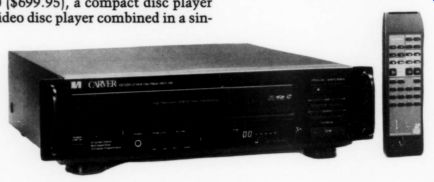
Carver has also announced the MD/ V-500 ($699.95), a compact disc player and video disc player combined in a single, attractive component with distinctive Carver styling. This versatile audio/ video source can play 3" and 5" compact discs, 5" CDVs, and 8" and 12" video discs.
The unit uses an 18-bit digital-to-analog converter with eight times over sampling. The player's many features include programmable access to 16 video chapters or 16 CD tracks, full skip search, freeze and frame-by-frame ac cess, multi-speed scan, direct digital output, and variable headphone volume.
It also has on-screen and front-panel displays, plus a full-function remote control.
For more information, contact Carver Corp., PO Box 1237, Lynwood, WA 98046-1237, (206) 775-1202.
Sescom has available a catalog of new products. It includes new product areas as well as extensions of other product categories. Categories are isolator series, hand-held test equipment, field pro series, new portables, and rack electron ics. For a catalog, contact Sescom, Inc., 2100 Ward Dr., Henderson, NV 89015 4249, (702) 565-3400, FAX (702) 565 4848.
R.F. Engineering has announced the AC-8, a two-channel, current-sensing programmable power panel that can detect when two pieces of equipment are activated. Eight switched outlets can be programmed to switch on when either sensed equipment turns on. You can also individually program each outlet for delays in power-on and power-off to allow sequential switching of equipment. The AC-8 features an external control link that lets it be activated by home automation systems and full home audio/video systems.
For more information, contact R.F. Engineering, Inc., 9215 Lowell Blvd., Westminster, CO 80030, (303) 430-8281, FAX (303) 430-4023.
NAD has introduced the Model 5425 CD player. It uses one-bit digital-to-analog converter technology for music-decoding accuracy and one-bit converter implementation--such ‘peripheral’ concerns as power supplies, circuit layout, and analog-filter design. It features 16 track random-access programming, bi-directional track skip and audible fast search, 3" ‘CD-single’ disc compatibility, and wireless remote controls. The unit also incorporates a low-inertia three beam laser pickup/disc drive.
The 5425's specifications include the following: frequency response, 5Hz 20kHz, +-0.5dB, A-weighted S/N (emphasis-on), 110dB; dynamic range, 98dB; total harmonic distortion, 0.0025% (IM is suppressed 100dB or more); channel separation, 100dB.
The unit sells for $299 (with remote). For more information, contact Bryan Stanton at (212) 752-1600.
Alpine Electronics of America has introduced their 5951 compact disc remote changer CD Shuttle with keypad controller and FM modulator package. De signed to simplify its addition to OEM or aftermarket systems by using an FM modulator, the 5951 installation is further streamlined by its two-piece controller/modulator. Instead of having separate RCA-type connectors for audio, the device will transmit audio through its DIN cable, simplifying installation and reducing noise problems.
The 5951 uses 8x oversampling, 18-bit hybrid digital-to-analog converters, and digital deemphasis/noise shaping. It also employs Alpine's DR-mechanism for trackability and 20% faster disc changing times. The unit can be mounted 30° from the horizontal or vertical position and the keypad controller is easy to install.
The 5951 sells for $620. For more in formation, contact Richard Frank at Frank Marketing Associates, 8 Mohave Rd., Medfield, MA 02052, (508) 359 5977, FAX (508) 359-5343.
Analog Devices' AD745 monolithic FET input operational amplifier combines the ultra-low voltage noise characteristics of a bipolar input amplifier with the inherently low current noise of a FET input device. Its 0.0002% THD at 1kHz makes the device an excellent preamp or current-to-voltage converter in systems with high-source impedances.
The AD745's combined low offset voltage and noise performance support a minimum of 140dB dynamic range. It is available in six performance grades, housed in an 8-pin plastic DIP, cerdip, or 16-pin SOIC package. Specified operating temperature ranges include 0-70°C, -40t o 85°C, and -55 to 125°C (S grade). S-grade amplifiers are available processed to MIL-STD-883B.
Prices begin at $3.36 in 100s. For more information, contact Analog Devices, Inc., 181 Ballardvale St., Wilmington, MA 01887, (617) 937-1428.
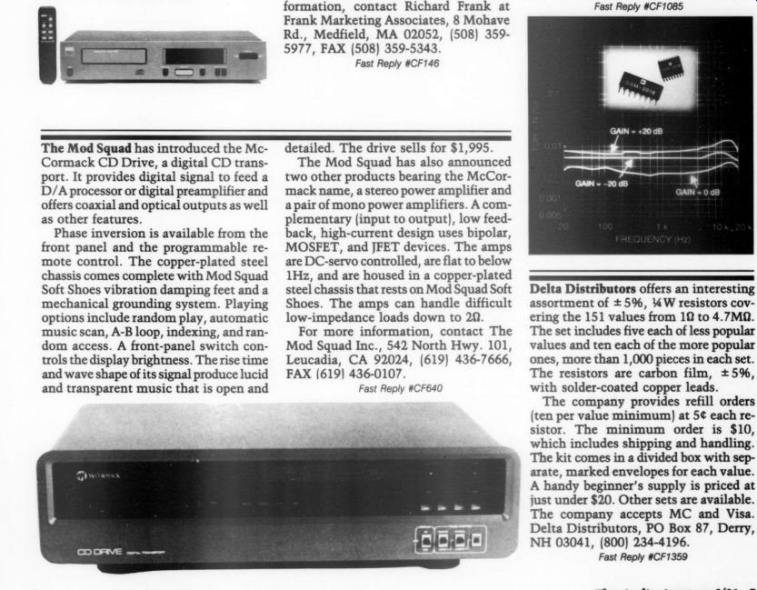
The Mod Squad has introduced the McCormack CD Drive, a digital CD trans port. It provides digital signal to feed a D/A processor or digital preamplifier and offers coaxial and optical outputs as well as other features.
Phase inversion is available from the front panel and the programmable re mote control. The copper-plated steel chassis comes complete with Mod Squad Soft Shoes vibration damping feet and a mechanical grounding system. Playing options include random play, automatic music scan, A-B loop, indexing, and random access. A front-panel switch controls the display brightness. The rise time and wave shape of its signal produce lucid and transparent music that is open and detailed. The drive sells for $1,995.
The Mod Squad has also announced two other products bearing the McCormack name, a stereo power amplifier and a pair of mono power amplifiers. A complementary (input to output), low feed back, high-current design uses bipolar, MOSFET, and JFET devices. The amps are DC-servo controlled, are flat to below 1Hz, and are housed in a copper-plated steel chassis that rests on Mod Squad Soft Shoes. The amps can handle difficult low-impedance loads down to 29.
For more information, contact The Mod Squad Inc., 542 North Hwy. 101, Leucadia, CA 92024, (619) 436-7666, FAX (619) 436-0107.
CE Delta Distributors offers an interesting assortment of + 5%, 4 W resistors covering the 151 values from 1 ohm to 4.7 M-OHM.
The set includes five each of less popular values and ten each of the more popular ones, more than 1,000 pieces in each set.
The resistors are carbon film, 5%, with solder-coated copper leads.
The company provides refill orders (ten per value minimum) at 5¢ each resistor. The minimum order is $10, which includes shipping and handling.
The kit comes in a divided box with separate, marked envelopes for each value. A handy beginner's supply is priced at 4 just under $20. Other sets are available. The company accepts MC and Visa. Delta Distributors, PO Box 87, Derry, NH 03041, (800) 234-4196.
Editorial
Get Going
Every audio amateur has one thing in common with every other: projects-mostly unfinished. We are a band who live on hope and anticipation. But that ingredient is usually far larger than it ought to be for a healthy avocation.
I have found, having files full of un-begun projects, several which are stillborn from having become obsolescent. They looked like good ideas, and probably were, had I gotten them started.
Lately I have been spending time documenting a proposed project with the hope of completing it. This consists of gathering relevant data in a file folder, from a synopsis of the first idea, and perhaps a copy of an article or two which started the concept. Usually a parts list begins to form and also ideas on where I might find the parts.
Eventually I pull down the catalogs and begin the search for what I need. This is also a good time to digress. I never search a catalog for a part without learning something. A well-written catalog is instructive about components, their relative performance factors, how they work, and what they do. No amateur deserves the name who hasn't a growing, evolving, up-to-date shelf of all sorts of catalogs. But keep your eye on the goal- locating the parts.
Once the parts are ordered and sitting on your workroom shelf, there is generally a pause. And the pause can sometimes stretch to years, or become terminal. How many parts do you own that were intended for some project which never came together in a working prototype? I suspect it is a universal hazard.
I began to wonder one day why my several dozen dream projects seemed caught in this limbo, some outer-space orbit where they circle endlessly and die of old age. It also dawned on me that I have built projects in two ways.
One is to spread all the parts on the bench (usually after one of my semiannual clearing-offs of all the detritus that gathers there: screws, nuts, a new package of gadgets picked up in a moment of weakness at Radio Shack, wire ends, and all the other stuff that accumulates while you're building something, or just making a new cable.
This clearing off is a matter of critical mass. Clearing your bench requires extraordinary motivation and the idea of laying out all the new parts which are all there together, deliciously promising something new and elegant for your system, and you begin to hand-fit things to a chassis. The whole approach is rather amorphous and usually without shape, direction, or result.
It works OK sometimes if it gets the project under way, but it usually turns out to be a mess and must either be rebuilt or begun afresh.
An alternative method is the older, and somehow more tedious, one of planning. Draw a block diagram, not only of the project itself to fully understand its elements, but of how this new bit fits with the rest of the system. Give time and thought to this process and put it in some form that someone else can read and understand. I often liberate, or buy, a loose leaf three ring notebook and label it. Then I punch holes in the planning sheets, parts order blanks, copies or originals that come with the parts, and place them in the book.
With this method, I find I have built a bridge which gets me started, and I have a plan to follow. I use quadrille or graph paper to do rough layouts for the box. Tape the sheets to the box and make sure the parts fit. By this time, of course, I find I am well on the way. The sheet metal punches come out, I assemble the needed size drill bits, and make sure my handy cordless is charged. (Although expensive, a second power pack is a wonderful comfort to have when you start a project.) I have treated myself to a new set of drills, titanium coated, which have tiny twin-points that keep the bit from wandering around trying to find the punched dimple. These are especially useful in the larger size bits whose points are broader and tend to wander more easily.
Keep notes as you work. Hard to do, but very handy if you plan to share your adventure with fellow amateurs. A photo graphic record is useful as well. Easy if you have a Polaroid, less costly in 35mm format. Try using Ilford's XPT-400 which acts like B&W 35mm film, but may be developed in a color processor. You get a bluish or sepia tone, but quite useful and convenient.
After completing drilling, punching and deburring, assembly usually goes quickly. In my early days when punches were expensive, I managed to buy one or two a year. Punches can con tribute amazingly to the neatness of your project and save a great deal of drudgery. I have been delighted to see that low cost sets of these great devices are available from Sescom in Nevada.
Tools are another area where planning and catalog browsing can be highly productive. Tool technology, especially in soldering, has developed in wonderful ways. Temperature controllable soldering stations are now relatively low cost and, considering the vital importance of soldering, such a tool is a sensible and prudent investment for the serious amateur.
Take time when at last the project is complete to do some realistic and rigorous tests. Record the results and put them in the project book.
After installing this new wonder in your system and checking the results, take time to reflect on how it could have been done better. Write out the notes on what you learned about technique, and what sort of mistakes you might avoid next time.
It is a truism that any new project requires at least three proto types. The first for making sure it works. The second for getting the layout and mechanics right. The third is for cosmetics--making it look as beautiful as possible.
I find planning techniques are helping me to get my projects out of the filing cabinet and into my music system. And the old rules I first heard crystallized in a vintage ice cream parlor in Marion, Massachusetts are still valid. As Viggo Petersen observed, if you're going to make good ice cream, or anything else, three simple rules are all you need: Use good stuff, keep good records, and please yourself. I'll add a fourth. Get going.
-E.T.D.
AUDIO AIDS
BALANCED VOLUME CONTROLS
IN HIS EXCELLENT ARTICLE on balanced audio circuitry, Erno Borbely discusses problems with balanced volume controls. [1] The ultimate common-mode rejection ratio (CMRR) of the dual-section per channel volume control (shown in his Fig. 18) depends on how well the two sections' resistance characteristics are matched throughout the rotation range.
Precise matching is difficult for conventional potentiometers.
The control sections can be realized with various types of stepped attenuators. The design equations are the same for the series stepped volume control whether used in an unbalanced single section or in a balanced dual section con figuration. The important thing to note is that the resistance ratios are the same for the unbalanced and balanced con figurations. Matching of the resistors be tween sections should produce a high CMRR. Also, the mechanical layout should be the same for both sections to prevent leakage variations from degrading CMRR at high frequencies.
I think Mr. O'Connell? dismisses other types of stepped volume controls too quickly. Others, beside myself, believe the multiple resistors and solder joints of the series controls audibly degrade sound quality, at least in the unbalanced configuration. It would be illuminating for someone to perform listening tests to determine whether audible distortions cancel in a balanced con figuration.
The topology shown in Fig. 1 allows you to adjust volume using a single control while maintaining balanced operation. CMRR is mainly controlled by the match between the two halves of R1 and R2, which are fixed resistors. The circuit in Fig. 1 does involve some compromises. If R3 is a conventional, audio potentiometer, the circuit will have a fixed loss and the attenuation versus rotation curve will be compressed.
Table 1 shows attenuation versus rotation for an Alps 20 k-Ohm audio taper potentiometer used as a normal, unbalanced volume control and for two cases of it used as R3 in Fig. 1. I computed attenuations from measured resistances.
The input resistance of Al was assumed to be much greater than R2. Intermediate rotations were ‘eye-balled. ’ The finite attenuation at zero rotation reflects a real, rather than ideal, component.
In many situations, use of a standard control may be adequate as most systems have excessive gain. You can minimize the fixed loss and customize the taper by switching fixed value resistors for R3. Figure 2 shows one possibility using dual, shorting (make before break) switch sections. Even though two switch contacts are in the signal path, some of their effects will be cancelled by the differential amplifier.¢ Note that between switch steps, level will be reduced approximately 6dB when two resistors are shunted.
Assuming A1's input resistance is much higher than R2, you can compute R3 using:
R3 =(G/1- G)R2
Where G = 10 db /20 (dB is the desired attenuation in decibels). Note that dB is a negative value. When dB = 0, R3 is an open circuit.
Choose R1 to minimize change in input resistance as R3 is varied.
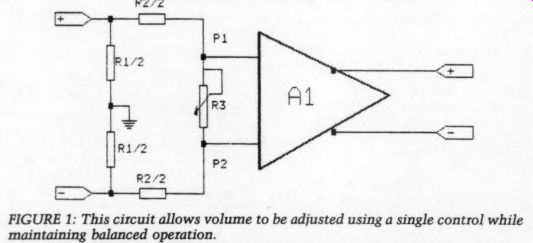
FIGURE 1
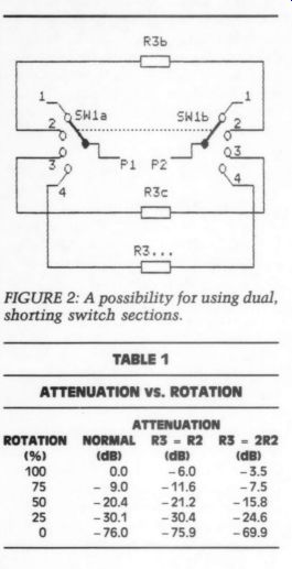
FIGURE 2: A possibility for using dual, shorting switch sections.
TABLE 1
ATTENUATION vs. ROTATION
Since most components with balanced outputs can drive fairly low impedances, it should not be difficult to find an accept able value.
A dual-concentric, switched control is convenient for adjusting volume and balance and it minimizes the number of controls in the circuit. Unfortunately, suitable dual-concentric switches are in short supply. I made one, with 1dB steps, from a pair of 32-step switches. The tricky part is to drill a hole through the front control's 0.25 " shaft for the 1/8" rear switch shaft.
After disassembling the control, have a machinist drill the hole with a lathe.
I used a standard 1/4 " coupling and a 1/8" to 0.25" bushing to adapt a 1/8 " shaft to the 0.25" rear control shaft. I attached the rear switch to the front using threaded stand offs. Large (2.5 " diameter) knobs let you easily control both channels. Drill the rear knob to allow the shaft from the rear switch to extend out the front. Another bushing lets you secure the front knob to the 1/8" shaft. To minimize flexing of the 1/8" shaft, keep it as short as possible.
For volume control use, you probably should lighten the torque of the detent mechanisms. When you are satisfied with the control's mechanical operation, use LocTite to prevent loosening of the hardware securing the 1/8 " shaft to the switch and knob.
FRED GLOECKLER, Woodbridge, VA 22192
REFERENCES:
1. Borbely, Erno, Balanced Audio Amplifiers, TAA 1/91.
2. Gloeckler. 'Switched Attenuators,' TAA 2/72, p. 14.
3. O'Connell, Joseph, ‘Computer Programs for Stepped Volume Controls,' TAA 4/88, p. 43.
4. Hupp, Leonard. 'A Ladder Attenuator,' TAA 5/82, p. 20.
5. Didden, J.M., 'A Remote Control Volume/Balance System,' TAA 2/91, p. 24.
6. Kerridge, B., 'Precision Parts Demand Kid-Glove Treatment, ‘ EDN, February 18, 1991.
CALIBRATING FREQUENCY COUNTERS
I HAVE NEVER been at a loss without a frequency counter, but at times a good frequency measurement can be very useful.
Quartz crystal-based frequency counters are very accurate, but are still relatively expensive, given the time the average amateur will use them. Some of the more recent digital multimeters, however, now incorporate a frequency counter, al though their accuracy is generally around 2%. This is satisfactory for most purposes. But what if you must be more precise or simply wish to find out how ac curate a meter is? If you own a CD player, you can calibrate an inexpensive counter at a number of spot frequencies within the audio range. Several test CDs, such as those from Pierre Verany, CBS, or Hi-Fi News & Record Review, contain spot sine wave frequencies between 20Hz and 20kHz (the new HFN/RR test disc contains frequencies down to 2Hz). These are accurate to within the accuracy of the crystal oscillator in the player or to the same or der of accuracy as a crystal-referenced frequency counter (approximately 0.01%).
Hook up your counter to your CD player and write down the counter readings as the player marches through the relevant test tracks. Then you will know that, for example, if your counter reads 2040 for a 2kHz tone, it will read about 2% higher in this frequency range, and you can compensate accordingly.
JAMES LIN; Galveston, TX 77551
Showcase
FOND FAREWELL
by John W. Newman
Dear Editor: I have periodically received notices from you urging me to re-subscribe to Audio Amateur. With regrets, I ask you to remove my name from your mailing list in the interest of helping you purge it for more economical operations.
My interests have departed from audio experimentation. Nowadays I service computers during the day and have a side business of building, repairing, and re storing clocks, which is a full-time hands-on avocation.
I now even use a commercial stereo while working on the clocks. I switched because the system I built would not lend itself to fitting in with my current one, which is running the TV audio through the stereo system with a surround amplifier. My home-built setup was in the back of the room (with speakers in the front); the new hookup uses remote control, which does not work well when aimed at the rear of the room. Don't even mention using mirrors! I have rationalized that my limits are determined by what my aging cars can enjoy, not by what spec sheets my eyes Photos 1 and 2 show my system just before I sold it. The tuner is a Dynaco FM-5, the preamp a Dynaco PAT-4 with some TAA mods, the tape deck a Sanyo RD5350, the turntable a Dual 1019, and the control panel (Dynaco Quadapter, multi-speaker switching, main power switch) and power amp (Photo 3) were my own design and making. I never had the amp tested, but the output transistors were Westinghouse military types with 6A collectors. They did not even get warm! This was all housed in an antique Victrola cabinet to fit in with my antique decor.
When I do meet people interested in audio experimentation who wish to get something better than what they can obtain commercially, I do not hesitate to tell them about your institution, and it is that, not just a magazine. Your following of audio amateurs is a cut above the so-called professionals of the commercial world because they truly love what they do and produce far better results. [Vale, John, and thanks.-Ed.]
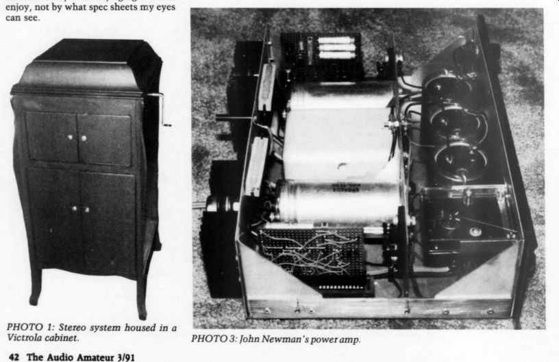
PHOTO 1: Stereo system housed in a Victrola cabinet.
PHOTO 3: John Newman's power amp.
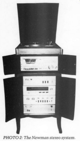
PHOTO 2: The Newman stereo system.
LETTERS
THE LT PREAMP
TAA READERS MAY LIKE to know about a bargain toroidal transformer for the Linear Technology preamp. Parts Express (800-338-0531) has a dual 20V, 5A toroidal transformer for $13.90 and it works great in the preamp. Its part number is #120-150.
I have built and tested the LT boards and believe I have caught all errors. The differences between the boards and the published schematics follow:
I put 0.01 or 0.001 uF caps in parallel with all the 1.0uF bypass caps.
I put 0.1 and 0.001uF caps in parallel with the 2,200 and 4.7uF caps that pro vide bypassing in the feedback loop of the RIAA stage.
I used LM334s as current sources in the RIAA stage and line stage instead of the FET shown in the RIAA stage.
The RIAA stage has two 3,900pF caps. used some precision Rifa 3,880pF caps from my junk box. The layout spacing reflects the size of the caps I used.
To do the board layouts, I purchased a copy of Quick CAD PCB version 1.2 from Micro Design. The program produced usable designs, but I have a few reservations as to its quality.
I found that only the simplest boards can be laid out using the program. The limiting factor is memory. I have 5Mb of memory in my PC, but the program recognized only the 640K of base memory and that memory went away quickly as I added objects to the design.
Another limiting factor is speed. As circuit complexity increases, the program gets slower and slower to use. It redraws the screen after almost every operation; each redraw takes perhaps seven seconds on a circuit with the complexity of this power supply. Even on an 80386 machine, it was slow. To compound matters, deleting a mistakenly placed trace
--------------
NORMAN H. CROWHURST: 1913-1991
I am profoundly saddened to report that Norman H. Crowhurst died on March 7, 1991 after a brief illness. He was 77. Born November 3, 1913 in Southend-on-Sea, England, he earned degrees at Streatham Hill College and at Goldsmith's College, S.E. London Technical College, where he was later a senior lecturer. Mr. Crowhurst's career began at Johnson & Phillips Ltd. In 1935 he became Chief Engineer at Tannoy, Ltd. where he remained for ten years.
He and his wife emigrated to the US in 1953. He was honored with a Fellowship by the Audio Engineering Society in 1959. He and Mrs. Crowhurst became naturalized citizens on Nov. 17, 1960.
Norman Crowhurst was certainly one of the most prolific of authors in the audio field, having contributed to 32 commercial publications and many professional journals. He once claimed that he had written more than 2,000 articles and papers and some 50 books. He also held a number of patents.
He was an associate member of the British IEE, Senior member of British Sound Recording Association, a member and fellow (1959) of the AES, a member of SMPTE, IEEE, ASE, National Council of Teachers of Mathematics, and Professional Engineers of Oregon.
He worked as editor at several British and US publishing houses both on staff and as a consultant. He also spent two years working at Fairchild Re cording Equipment Company.
Mr. Crowhurst was best known to electronics buffs, and especially audiophiles during the 1950s and '60s, as a well-known author on audio theory and construction. He developed many unique answers to problems, such as a stereo power amplifier which sported only one pair of out put tubes but two transformers. He had an unusually clear writing style and an exceptional ability to explain difficult theoretical concepts in terms beginners could understand. He had a remarkable number of admirers among his readers who credited him with being the first author to stimulate their appreciation for audio and electronics.
In mid-October of 1990 the bicycle he was riding was struck by a passing car, in his adopted home town of Dallas, OR. Medical examination revealed little or no obvious damage but he failed to recover completely. He be came ill in late February and was bed ridden for much of each day. His death came suddenly from heart failure.
-----------------
... requires exiting and entering several layers of menus and several redraws. This was quite frustrating.
Also, what you see on the screen is not necessarily what is printed. It is close when the circuit is printed at 100 dots per inch, but at 300 dots per inch, I found my screen quite different from the print out. There seems to be no way to display or edit a circuit at that resolution.
The manual does not describe how to use the program, and the on-line help is of little help. Learning to use the program is a matter of trial and error.
Enough about Quick CAD PCB, and on to other things. have been unable to locate a US source for the Toshiba FETs used in Erno Borbely's preamp, but Time Lord in Japan (3-5-10, Shinjuku, Zushi Shi, Kanagawa 249) supplies them.
I have written a stepped-attenuator program in C for IBM-PC compatibles.
I didn't have Mr. O'Connell's program and didn't care to wait for it. I did have a copy of the 2/72 TAA issue, though, with Mr. Gloeckler's article on stepped attenuators. This program is based on that article. It doesn't have fancy 1/0 routines, but it is quite usable. It produces a list of resistor values in order from the top of the attenuator to ground.
DAVE HALBAKKEN; Pauma Valley, CA 92061
A note from the Editor:
We reproduce the Linear Technology board pattern and stuffing guide for those who are interested. Copies of the source code for the Gloeckler attenuator are available for a #10 stamped, self-addressed envelope addressed to the magazine and marked Editorial Department.
Copies of the program on an IBM 360K disk are available for $7.50 plus $2 shipping and handling from Old Colony. Ask for part number SOF-GSA1BS.
Although Micro Design's program has the limitations cited by reader Halbakken, it is quite inexpensive. The alter natives begin at $500 and go as high as $50,000.
I READ WITH INTEREST Mr. Laszlo's ‘Audio Aid' in TAA 2/91 (p. 62), wherein he discusses a tube circuit he calls SRPP.
He attributes the invention of this circuit to Anzai who published an article about the circuit in the French magazine L'Audiophile. To set the record straight, the circuit dubbed ‘SRPP ’ was discussed extensively at least as early as 1948 by MIT professors Valley and Wallman in Vacuum Tube Amplifiers, published by McGraw-Hill. (See their section on direct-coupled amplifiers.) They refer to the circuit as a Two Tube Series Amplifier (TTSA). Its topology is identical to that of the SRPP.
In discussing this circuit, Mr. Laszlo refers to a design I proposed in an earlier letter (TAA 2/85, p. 53) as being essentially the same as the SRPP. The two circuits, however, have an important difference-the circuit I discussed has a much lower (easily better than a factor of 10) output impedance and a better power supply rejection than the TTSA/ SRPP circuit. Also, as a side benefit, the gain increases from the pu/2 of the TTSA/ SRPP to the x of my design (x being the familiar triode amplification factor). Because of the low output impedance of my circuit, its gain of x, and the need to distinguish it from the TTSA/SRPP (at least for the balance of this letter), I will refer to the circuit as the ‘u (mu) follower. ' To get an idea how these two circuits, as well as two other common designs, perform, refer to the schematics (Figs. 1-4) and their associated general equations for output impedance, gain, and power supply rejection ratio (PSRR).
Typical component values are supplied for each circuit, and the general equations have been evaluated using these component values co provide numerical results for the purpose of comparison.
Figure 1 is a simple resistor-loaded single-tube design. Its gain has been set to the u/2 exhibited by the twin-triode TTSA/SRPP design in Fig. 2. Figure 3 takes the single-tube design and tacks on a cathode follower. (For those disturbed by ‘naked ’ cathode followers, a buffering resistor is placed between the follower's output and its load.) Finally, Fig. 4 is the u follower.
The gains of the first three circuits are virtually identical. The output impedance of the TTSA/SRPP is lower than that of Fig. 1, but not nearly as low as that of Fig. 3. Also, the vaunted linearity of the TTSA/SRPP approach is no better than that of the first and third circuits. This is because the top tube in the TTSA/SRPP design supplies the same load to its bottom tube as does the plate resistor in Figs. 1 and 3. (The magnitude of the plate load in a triode amplifier pro vides the most important contribution to linearity.) Regarding PSRR, I disagree with Mr. Laszlo's assertion of the poor PSRR of the TTSA/SRPP. As the supplied equations indicate, the PSRRs of the first three circuits are much the same be cause (as mentioned earlier) the top tube circuit in the TTSA/SRPP looks to its bottom tube much like the plate resistor in Figs. 1 and 3. The TTSA/SRPP out put tends to follow the voltage at the bottom tube plate closely (the output of the first and third circuits) resulting in the same PSRR.
The mu (u) follower design would seem to offer the best overall performance. Its gain is almost u (mu) which is not so important in itself, but highlights the fact that the top tube is providing a very high impedance, nearly constant current source load to the bottom tube. Such a load supplies the enhanced linearity characteristic sought after but missed in the TTSA/SRPP implementation.
As far as output impedance goes, that of the u follower is less than Y, that of the TTSA/SRPP, although not quite as low as that of Fig. 3. However, the u (mu) follower shines in the area of PSRR, being much better than the first three circuits. You can understand this when you realize the top tube circuit is virtually a constant current source. As a result, B + voltage variations produce negligible changes in the current through the top tube and therefore through any of the p follower components. (The top tube plate absorbs virtually all the B + voltage variations.) Accordingly, the bottom tube does not see the B + variation, so its plate voltage and the voltage drops across the circuit's resistors remain stable, affording an excellent PSRR at the output.
The design of the u follower resulted from my reading a work Brian Clarke did on the TTSA which referenced the Valley-Wallman book. Mr. Clarke was also looking to reduce the TTSA output impedance. His approach involved connecting the negative terminal of a battery to the bottom tube plate of the TTSA, disconnecting the top tube grid from the bottom tube plate, and reconnecting it to the battery positive terminal. This allowed him to increase the value of the top tube cathode resistor, increasing the load impedance which the top presented to the bottom, while maintaining the same bias current. (Valley and Wallman also investigated this approach, but with a circuit similar but not identical to the TTSA.) In the u (mu) follower approach, I replaced the battery with two resistors and a capacitor to achieve the desired results.
This scheme works best when the value of R, is maximized subject to minimum plate voltage and current constraints for the triodes. I have never come across the p follower in publications prior to my original letter, but I am cautious about claiming credit for its invention. Can anyone refer me to a pre-1985 publication discussing a circuit with the u (mu) follower topology?
-------------
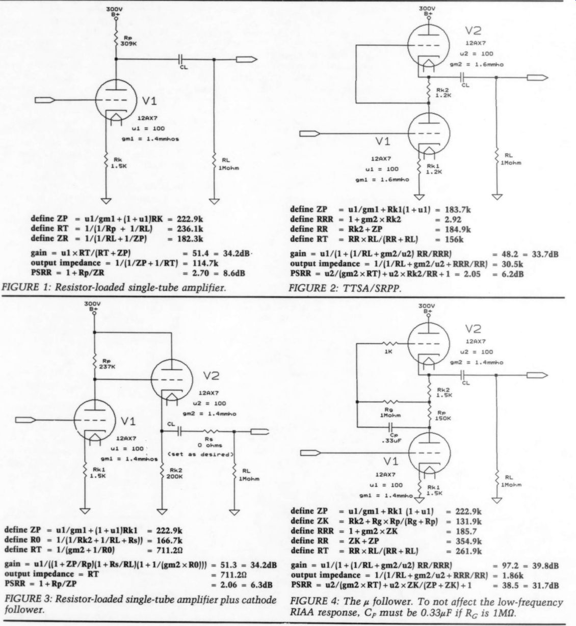
FIGURE 2: TTSA/SRPP.
FIGURE 1: Resistor-loaded single-tube amplifier.
FIGURE 3: Resistor-loaded single-tube amplifier plus cathode follower.
FIGURE 4: The u follower. To not affect the low-frequency RIAA response, Cp, must be 0.33uF if R. is 1 M-OHM.
---------------------
Finally, I note that the circuit Mr. Laszlo refers to as a modified SRPP has no connection to the bottom 6Dj8 grid.
(I assume this was not intended by Mr. Laszlo.) In any case, I believe the 24dB gain and 1.36 k-Ohm output impedance which he claims for this circuit could be closely matched by a simpler TTSA/ SRPP circuit consisting of a single 6DJ8 tube biased to 15mA with 80 ohm cathode resistors. (The circuit would also be much quieter than the one with a 12AX7 input.) Of course, even higher gain and lower output impedance could be achieved with a 6DJ8-based u follower.
CHRISTOPHER PAUL
Bayport, NY 11705
DANIEL FIXES
I'M SOMEWHAT OF AN electronics neophyte, so I purchased a used Curcio Daniel Preamp, built by one of your subscribers. I will share some minor problems I had with it, due, I believe, to an incorrect parts specification.
My preamp burnt out R125 and R225, specified as 1W metal films. I was unable to find any corrections in subsequent is sues that indicated they should have had a higher wattage rating. With help from a seasoned TAA kit builder, I attempted to find the problem. We replaced the resistors with 22k, 3W metal film resistors after adjusting the voltages via R8 as suggested in the 2/85 article. We changed Vier from 269V to 251V, Vc from 285V to 266V, and Vg; from 263V to 235V. The voltages across the new R125 and R225 now were 190V and 182V.
This computes to approximately 1.6W dissipated by each resistor.
We tried various 6Dj8s in the circuits during the debug process: 6922s, 7308s, and straight ECC88s. All seemed to vary the current draw (hence power dissipation) of R125 and R225. I believe my Daniel is substantively stock (it employs a variant of the recommended off-board power supply, omitting the TRIAC and the relay).
I measured every resistor on the board and my friend double-checked the circuit. Any Daniel owner can verify my observations simply by measuring the volt age dropped across R125 and R225.
Assuming my preamp is typical, I can make the following observations about current
Daniels:
R125 and R225 are operating on the fringe of burnout. Joe Curcio specified the power supply voltages of = 10V. Being on the plus side of the spec increases the exposure.
If an owner experiments with different types of tubes, it is possible a small percentage extra current draw could fry R125 and R225 if they are operating ‘on the edge.’
You should replace R125, R225 with higher wattage resistors and solder them with board clearance to allow for breathing to help dissipate heat.
My Daniel is very stable with the above changes. My line stage incorporated the change Joe suggested ( ‘Mail box, ’ TAA 4/85, Fig. 1) to increase the output impedance.
Despite the problems, I like the pre amp very much. My previous preamp was a Superphon Rev Il which I enjoyed, but the Daniel line section is outstanding. The phono section is only a pinch better (but sonically very good). I am accustomed to my best records sounding better than CD, so I believe some tweaking in the phono section still remains (CDs and vinyl sound about equal now).
I run premium quality RAM 6Dj8s for tubes. I have relatively good equipment, so shouldn't the phono section sound superior to CDs as in my previous pre amp? I purchased the Old Colony inverse RIAA kit to help answer that question.
BILL SZYMANSKI; Hartford, CT 06106
REGULATION METHODS I HAVE BEEN an avid reader and audio amateur for the last ten years. James Boak's efforts in this magazine have given me the opportunity to gain knowledge and enjoy my hobby in a way unavailable from any other source.
I am an experienced builder and modifier, but I'm no designer. I've had no for mal training and owe my knowledge to TAA and suggested readings. Although at times I am comfortable with the de tails (understanding and executing), my knowledge has significant gaps that often lead me in the wrong direction or just leave me stumped and frustrated.
I've been using a POOGE'd Hafler DH 200 (full treatment with Boak regulators) with much pleasure (and reliability) for more than six years. I've decided it's time to construct a successor.
I am planning to build the Borbely DC100A in a configuration that will ex tract the maximum performance with out a concern for parts, costs, heatsink area, and so on. I will build the units as fully mono amps, each on a separate chassis, and will use six pairs of output devices per amp as per Borbely (TAA 2/89, p. 7). I will use the amp with a dynamic loudspeaker, which does not pre sent any extreme current demand. However, based on my current reading, [ hope to hear some benefit from a high current/load-insensitive ‘ideal amplifier ’ approach. My questions concern power supply regulation to each stage and the regulation method to employ.
My basic plan is to regulate the early stages separately from the output stage.
A completely separate supply for the first stages will include separate transformers. For the output stage, I will use two 1kV/A transformers per mono unit, one for the positive rail and one for the negative. Tentative specifications for the transformers AC 2 X 65V/7.69A with secondaries in parallel 86.5V DC/6.8A regulated down to 65V DC per rail.
I've included my questions to Mr. Borbely as you may be able to add some comment.
Is there any benefit and how would I change the design if there were a + 20V DC (+ 24V) regulated supply to replace the zener string and current source? There seem to be many suitable and re liable +20V DC supplies from preamp designs.
What is the ideal voltage for the first/second stage and do you have suggestions for a regulation circuit for this stage?
Do you have any comments or suggestions on the output regulation circuit? My choices seem to be Jim Boak's (TAA 1/80, p. 6) or Kit Ryan's (TAA 4/89, p. 34). I'm concerned that this circuit will not current limit the output.
Can you offer any other advice given the parameters? My questions to you are:
Can I add pass devices to your regulator to increase the current available? Any concerns? What is the optimum capacitance before and after the regulators (or how do I calculate it)? I will use a soft start circuit to minimize any problems at turn on, feeding the line AC through a 50 ohm (or other?), 50W resistor for approximately 15 seconds before shorting it with a relay.
Do you have any comments on Kit Ryan's regulator?
PAUL H. LEVIN; New York, NY 10010
Contributing Editor James Boak replies:
You can add pass devices to increase the available current; however, single de vices with a current capacity of 30A are readily available (they are supplied with the Nelson Pass version of the kit), and you can obtain 50A devices with a little work. The demands of this amp would probably not exceed 15A even into a highly reactive load. All you must do is adjust the current control resistors as I describe in the article.
The thing to watch with these high currents is total power dissipation. Under normal circumstances, each rail pro vides half the total load power. Likewise, in steady state, the load current cannot exceed the RMS supply current. However, in a short circuit, or into a reactive load, the pass element may briefly have to carry as much as 15A (supplied by the input caps). Under these circumstances, it will have about 8V across it at 15A.
This will produce about 120W of heat, well within the device's short-term capacity if the heatsink is less than 100°F.
I recommend using a single 150W, 30A device, on a big heatsink. The devices Old Colony supplies will withstand al most any abuse at currents up to 15A.
Use the resistor settings specified for the Nelson Pass amp, and the zeners for the Williamson (which you can adjust for 65V DC output).
If you choose to use two devices, both of the big pass elements must have the same rating, as they will be dividing the 20V difference between your raw supply and the load. In other words, double up on both if you double up on either.
To parallel the pass elements, tie the collectors of the two (or more) devices together. Likewise, tie the base leads.
You must tie the emitter leads through a small resistance to control current sharing; this should be 0.022, 5W. You can use this parallel transistor much like a single resistor with the various units' combined current and heat capacity.
Optimum capacitance for the input side is 5,000 uF per amp of max RMS load current. For the output side, the value is 2,000uF per amp of max RMS load current, well bypassed with low ESR caps in accordance with POOGE principles.
When you're limiting current on start up, the 50 ohm value may be a little high.
Even 20 ohm provides an adequate cushion for input components.
I have not built or used Kit Ryan's regulator, so I can't speak for or against it.
I plan to see how it does work at some point in the future.
Your plans are interesting and ambitious. Please let me know how you progress. I will be glad to offer any assistance I can provide.
NAD 52555 HELP
I HAVE READ the many recent articles on greening the Magnavox machines, Yamaha and Sony CD players, and I find myself getting a bit green-with envy.
I have an NAD 5255, which I have improved a bit with a new output caps, but I have no idea how to proceed with respect to the D/A and filter chips. The other circuit mods (power supply changes and op amp upgrades) would be easy to implement now that I have the circuit diagram before me, but information on substitutes for the other chips is lacking. Could any of your contributing | editors or readers help me? The D/A converter chip is designated TD6705AP, and the low-pass filter chips are AFL89GB and contain an op amp as well. The uPD40553BC is likely to be a filter chip too, as it precedes the op amps in the analog section.
I would appreciate any help in modifying this machine. It is significantly inferior to my vinyl setup (which uses an Ortofon XM-3 cartridge into an NB-1 preamp) in terms of the immediacy or liveness of the recorded performance.
The effect of the cap mod I've done gives me hope there's room for improvement.
ALAN P. TOWBIN; New Haven, CT 06511
WHITE NOISE
THINKING THE CAPACITORS in the pink noise filter took part only in determining the slope, I never realized the out put at the 43k resistor should not see DC ground. I installed a 2.2uF NP 50V electrolytic between ground and the 1.8k resistor (Fig. 1) and it worked perfectly.
I used a nonpolarized cap only because I had plenty from audio work.
PAUL LONGTIN; Worcester, MA 01603
Bernhard F. Muller replies:
Thank you for calling my attention to a clear error on my part in the design of the white filter (SB 4/84, p. 16). I was apparently so certain no one would wish to have a white filter that I didn't proof read that schematic properly. In the seven years since the article has been published, you are the second person to call that error to my attention. The first occurred a week ago. Is there a sudden rush by the audio community to use white noise! When the filter is used in the original form, the op amp is biased into cutoff by the voltage divider action of the 43k and 1.8k resistors. The fix is to return the bottom of the 1.8k resistor to a positive voltage that is at AC ground. The most convenient way to do this is to follow Fig. 2.
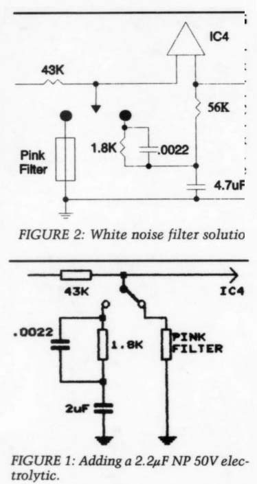
FIGURE 2: White noise filter solution.
POWER REGULATOR HELP
I AM NEW to the world of electronics and it is a foggy world to me, although the fog is being burned away as I learn more about electronics.
However, I can follow directions and I'm gathering parts to build Hans Mortensen's DC300B hybrid amp from TAA 1/89 and 2/89.
I would like to use Kit Ryan's output power regulator (TAA 4/89, p. 34), but I'm unsure if it will work with the + 63V no-load power provided by the 2X45V transformers specified. 1 will build it in dual mono with a 2X45 225-250VA transformer and a pair of 10,000uF caps per channel.
I'm not worried about less power out put from the amp. My small room and Jordan speakers couldn't use the full power anyway although all that head room would be nice.
Any help with parts changes, if necessary, to allow it to work in my application would be appreciated.
Otis Lewis
Stephens City, VA 22655
Kit Ryan replies:
The circuit should work fine in the DC300B if it can be physically mounted to a good heatsink. I suggest you run the amp without the regulator first and determine the lowest voltage dip at the raw * 63V supply under heaviest load.
Then set the regulator to about 3V below the 'dip' readings. This will probably be in the neighborhood of + 50V at the regulator output. It has a range of 45 90V as designed. If you need lower volt ages, drop R7 and R22 down to 3.9Kk (vs. 5.6k) and be sure they are ¼ W.
ADD DAMPING THE EFFORTS OF contributors David Foxon, David Ponta, and others regarding resonant structures in CD players ("Letters," TAA 2/91) have been mirrored here.
Most electronic structures I've seen are long on elasticity and rigidity (springy members), but short on damping (dissipative behavior). These undamped spring structures all have resonant frequencies, usually easily excited. Add damping.
My CDB-472 and AR turntable both rest on Sorbothane feet, which capture energy and dissipate it into heat. Across the top of the CD player rests a 2 1b. slab of iron, with a large paint-protecting rubber-band surrounding each end. The iron structurally ‘grounds ’ the thin iron shell and increases the preload on the Sorbothane. Though not beautiful like slate, it is extremely effective.
Adhesive-backed thin lead foil, marketed for the aviation industry, is used to damp acoustic vibration in the thin sheet metal structures. This and other dissipative layers will also work wonders in taming oscillatory members, correctly applied. Consult the Thomas Guide for a wealth of sources.
DARCY STAGGS
Orange, CA 92669
ARE MOVs PRACTICAL?
I FOUND L.B. DALZELL'S article ‘About Noise' (TAA 2/91, p. 10) very helpful.
It addresses many details in electronic construction and application that can affect noise.
In our increasingly electronic environment, surge protection with MOV varistors seems to be a smart idea. After reading the letter on page 71 of the same issue, I started to wonder just how smart it is. Michael Gergen points out, and Vern Mastel agrees, that fuses should be used between the MOVs and the power line conductors to prevent a fire.
I've built a few boxes with the three MOVs and gave one to a friend who lives in a rural area. After returning from work on a day when an interruption in electrical service had occurred, she discovered her stereo would not come on even though she had tried all the circuit breakers. She called me and I suggested that when the power returned, it might have caused a surge that shorted a MOV.
As she talked with me, she noticed smoke coming from the box with the MOVs. When I later disassembled it, I found the MOV between hot and neutral had blown, blackening the inside of the box. The MOVs had a rated ‘varistor voltage (maximum) ’ of 225V.
Use of MOVs appears to be a mixed blessing. Without fuses, they are fire hazards. With fuses, after the fuses blow, they no longer supply any surge protection. The fuses shown by Gergen are not in series with the electrical conductors so the ‘protected ’ equipment is still connected.
The photograph supplied by Mr. Dalzell appears to show a fuse holder on the boxes he built, but no mention is made of them. All commercial surge protection strips I have seen have a circuit breaker, which I assume is in series with the hot conductor.
LARRY GLENN
Eau Claire, WI 54701
L.B. Dalzell replies:
I have never experienced any problem such as you describe using MOV de vices. We did have a problem a few years ago, though.
A contractor (developer) was preparing the land near our home, and the powerline ran across the area. A tree removal crossed the powerline and the residential distribution lines. All over the area we lost power to all sorts of switches, lamps, computers, and sound gear. However, I had made extensive use of MOVs and lost power to only one light switch. As the MOVs were in metal boxes, I noticed only the odor of burned devices. Only a few master circuit breakers on the home supply opened during the incident.
Now, logic tells me the MOVs and the Siemens Surge Protector could be protected with series fuses, but the high power problem could exist long after the fuse blew, thus leaving the circuit un-protected. 1 do not advocate fuses in this position.
Looking at the specifications once more, surge protectors and MOVs can handle an astonishing current for a short period. Usually MOVs short when fully operated. The Siemens Surge Protector is considered self-healing and could be more to your liking.
The noise filters I built have a fuse I inadvertently omitted from the circuit drawing. It is in series with the line wire. It is there to protect the filter and this arrangement would be preferable to a fuse in series with the MOV. In this case, the MOV will truncate any high voltage and will assure the operation of the fuse, a 15A ABC15.
I hope this answers your concern about the use of surge protectors.
BOOK REVIEWS
AUDIO ANTHOLOGIES
Reviewed by Gary A. Galo
Contributing Editor Audio Anthology- Volume Two, com piled from Audio Engineering, January 1950 to July 1952 and Audio Anthology- Volume Three, compiled from Audio Engineering, August 1952 to June 1955. C.G. McProud, editor. Reprinted by Audio Amateur Press, Peterborough, NH. Each $16.95 from Old Colony.
TAA READERS WILL RECALL my enthusiastic review of the reprinting of the first volume of the Audio Anthology (TAA 1/88, p. 45). It has sold well enough to warrant further volumes, which are fine successors, offering much fascinating reading. Volume Two includes 45 articles from past issues of Audio Engineering, many of these authors now recognized as audio legends.
David Hafler, who needs no introduction, and co-author Herbert I. Keroes lead off with two articles on ultra-linear power amplifiers, the second being a modification of the famous Williamson design. The lead article's first paragraph reminds us little has changed since 1951. The authors point out:
'It has been claimed that there is no more room for improvement of power output stages since other elements of the complete sound system. . . are far inferior. There is a prevalent belief that 'one good amplifier is only marginally different from another.' The proponents of this line of thought imply that significant improvement in power amplifiers is extremely difficult to achieve, and with this idea the authors agree, but the authors disagree as to the need for further improvement."' Hafler and Keroes offer a design that optimizes the performance of tetrode output tubes to yield performance rivaling triode designs. Their unique arrangement energizes the screen grids from a tap on the primary of the output transformer. To modify the Williamson amplifier, replacing the output transformer is necessary along with a minor change in the feedback loop. Interestingly, arguments still persist among users and de signers of tube amplifiers regarding the merits of all-triode designs.
One of the most interesting articles is McProud's ' 'Recording Characteristics." Anyone still confused about disc equalization, constant amplitude, and constant velocity cutting will find this article as clear and as technically correct as any in print today. Also, his article on 'Construction Practice ’ is informative, covering parts selection, layout, and wiring practice. It begins by stating that ‘regardless of the design and layout, the final performance of an electronic unit depends upon its components and the way they are put together." McProud seems to be telling us parts quality may affect the performance (sound?) of our audio equipment. Today, with parts choices far more sophisticated than those in 1950, many designers still refuse to believe parts quality can make a difference in the sound.
Tenny Lode offers an article on ‘Stereophonic Reproduction, ‘ still a curiosity in 1950. The title is deceiving, how ever, as the article explains a method for creating electronically reprocessed stereo from monaural recordings. Those who still purchase reissues of mono recordings abhor such practices, since they usually degrade otherwise perfectly acceptable monaural sound.
By the late 1950s, all high-quality tube preamplifiers used DC filament supplies to reduce the hum level. L.B. Ledge, in his article ‘DC Heater Supply for Low-Level Amplifiers,' describes an outboard DC supply for operating phono and microphone preamps. One possible application for these circuits is G.H. Floyd's ‘A Mixer and a Preamplifier for the Recording Enthusiast, ’ which used an AC filament supply. Preamplifiers abound in this second volume of the Audio Anthology. The most extensive is Wade B. Denny's ‘For the Discriminating Listener: An Audio Input System."' This flexible six-input preamp features DC filaments for the low-level amplification, tone controls, and a dynamic range expander, which can be modified to function as a noise suppressor.
Ulric Childs' article, 'Dynamic Negative Feedback,' describes a system for using current feedback to counteract the varying loudspeaker impedance. His concept was most important at the time it was written, since vacuum tube amplifiers were rather sensitive to the load impedance presented by the loudspeaker. This is a contrast with modern solid-stage designs. Another article on feedback, by Warner Clements, explores the virtues of positive feedback to counteract the effect of the voice coil's changing impedance.
David Sarser and Melvin C. Sprinkle offer a sequel to the article printed in Audio Anthology- Volume One. ‘The Musician's Amplifier Senior' is a higher powered version of its predecessor offering an enormous 40W. The authors proudly state their previous amplifier has gained an enviable reputation in Europe and Australia for its excellent fidelity We are also told those who did not cheat on the quality of the parts used have been hearty in their praise." It is unfortunate some designers and builders believe parts quality is now good enough that even Radio Shack carbon film resistors are sufficient for high-performance audio equipment.
Several articles related to loudspeaker design are included. The bass-reflex loud speakers described appear crude com pared to modern designs based on the work of Thiele and Small. Nor will the horn theory appear sophisticated when compared to the work of Bruce Edgar.
Nonetheless, these articles provide excellent insights into the evolution leading to our present level of understanding. Volume Two is well worth reading.
Volume Three This volume of Audio Anthology contains 43 articles. Although power amplifiers form a small part of this collection, they present several interesting designs.
David Sarser and Melvin Sprinkle are household names to readers of the previous anthologies, and they return here with their latest version of their ‘musician's amplifier.' Called ‘The Maestro, ’ it incorporated the 6146 output tube, which had only recently been introduced by RCA. The authors note the usual 10-15W amplifiers lack the clarity and definition of live music in the concert hall. "The Maestro' boasts 90W of power from 25Hz-30kHz, an enormous amplifier for its time.
Stanley White describes an amplifier he calls the ‘Powertron.' An abundance of preamplifier designs are featured.
Wade B. Denney's 1954 article describes a dual-channel preamplifier that can be used for genuine stereophonic recordings or for creating pseudo-stereophony from monaural sources. His pseudo-stereo method employs multiple power amplifiers driving several loudspeakers, altering the tonal characteristics of the individual speakers to simulate a stereo effect. In Denney's opinion, the simulated stereo is preferable to a single monaural point source. Today, most collect ors of historical recordings are horrified when mono recordings are doctored for 'fake stereo. ’ Two other articles give further evidence of a new-found interest in stereo.
R.J. Tinkham clarifies the differences be tween binaural and stereophonic recording and reproduction in a 1953 article.
A photo in his article shows what he describes as a 'complete portable stereo phonic recorder, with amplifiers and power supply." Although he doesn't mention the brand name, the recorder is the famous Ampex 350-2, one I'm familiar with since the Crane School of Music had owned two. This three-piece ‘portable ’ recorder consisted of one case housing the transport (barely movable by one person), another containing two channels of electronics, and a third for the power supply. Putting handles on the cases made the 350-2 portable.
James Moir, in his 1952 article, ‘Stereophonic Reproduction ’ describes the reasons behind our ability to localize sound sources. Some startling information is presented in Mr. Moir's article.
He cites tests by Bell Labs ‘indicating that a stereophonic system having an audio bandwidth of 3,750 cps as having the same aesthetic appeal as a monaural system 15,000 cps wide. ’ Joseph Max field, co-inventor of electrical recording, is quoted as saying 'I would rather hear two-channel reproduction flat to 6,000 cps than a single-channel system flat to 15,000 cps; it is more pleasing, more realistic, more dramatic."' These opinions seem to run contrary to those expressed by many listeners in the late 1950s. Many audiophiles at the time were not willing to part with their wideband monaural systems, using very large loudspeakers, in favor of a two channel system with more compact speakers. Quadraphonic sound, in the early 1970s, was short-lived for similar reasons. For a given amount of money, most critical listeners preferred a two channel system that delivered true high fidelity performance to a mediocre four channel system. Of course, the lack of compatibility among the competing quad systems was another reason for its demise. I find it fascinating to discover how opinions have changed over the course of our audio history.
The lack of a standard for disc equalization is still evident in the preamplifier articles. Wayne Denny, in the article mentioned above, settled on the AES curve (later adopted by RIAA) since he believed it was the only one used to any great extent. Charles R. Miller, in de scribing a control preamp for the Williamson amplifier, offers five different LP equalization settings.
The transistor makes its first appearance in Basil T. Barber's article, 'A Transistor Phonograph Preamplifier for Magnetic Pickups. ’ Barber offers a tutorial on basic transistorized amplifiers and compares the grounded base, grounded collector, and grounded emitter configurations to their triode tube counterparts. His circuit is a two-transistor, feedback-based circuit using CK 721 and CK-722 devices. Barber gives a lengthy discussion about the advantages of using transistors and even recommends using tantalum capacitors de spite their high cost. According to the author, this preamp performs well in the listening tests, although he doesn't expect it to ‘render obsolete its vacuum tube counterpart." Would today's audio engineers find this preamplifier audibly indistinguishable from the best contemporary RIAA phono preamps, if the equalization and levels were matched within 0.1dB (double-blind, of course)? Volume Three features many designs for preamp tone controls and equalizers.
Stereo FM also makes its first appearance in the anthology. Editor C.G. McProud describes a two-channel converter for AM/FM receivers-not by adding a multiplex decoder to a mono FM radio, however. Instead, McProud offers a way to modify AM/FM radios so both receivers can operate simultaneously. At the time, some broadcasters were airing experimental stereo pro grams using an AM transmitter for one channel and an FM transmitter for the other.
No fewer than 12 articles on loud speakers appear in this volume. The early 1950s were certainly an age of large loudspeakers. Perhaps the article that drives home this point best is James Ferguson's 'The Concrete Monster.’ Ferguson describes a 16' concrete horn built into the side of his house. As the editor notes: ‘It could only happen in California. We envy his originality--as well as his apparent disregard for domes tic relations.’ Loudspeaker designers are finally paying attention to cabinet resonances.
Gladden B. Houck, of Hirsch-Houck Labs fame, provides a tutorial on internal bracing for bass-reflex loudspeakers, including mathematical justification for his methods.
Like the previous installments, Volume Three of the Audio Anthology pro vides a view of our audio history that is both entertaining and educational. I look forward to the remaining installments.
[Please see ad on the facing page for ordering information on Volumes 1-4.]
RECORDING HANDBOOKS
Reviewed by Gary A. Galo
The New Recording Studio Handbook, by John M. Woram and Alan P. Kefauver. First Edition, 1989, Elar Publishing Co., 203 Commack Rd., Suite 1010, Commack, NY 11725. 513 pages, hardcover, $44.50.
Sound Recording Handbook, by John M. Woram. First Edition, 1989, Howard W. Sams & Co., 4300 W. 62nd St., Indianapolis, IN 46268. 586 pages, hardcover, $49.95.
I'VE BEEN USING John Woram's The Re cording Studio Handbook for many years as the textbook for my Sound Recording class at The Crane School of Music. Mr. Woram's book is the standard text on sound recording, and most American colleges and universities offering degrees in the recording arts use it in their courses.
Mr. Woram and his former publisher (Elar) have parted company, in part, I suspect, because of Elar's inept handling of the revised edition of his book, which appeared in 1982.
The revised edition contained new chapters on digital audio, in-line recording studio consoles, and SMPTE time code-welcome additions to an already fine publication. The first edition of The Recording Studio Handbook, however, had several appendices that contained a great deal of useful information. The publisher deleted them in the revised edition, but not their references in the previous chapters.
I mentioned this to John Woram when I saw him at the Audio Engineering Society convention in New York a few years back, and he tactfully told me he was not happy with the way Elar was handling his book. At the same convention, I complained to the folks at Elar, but my comments were greeted with arrogance and abrasiveness. Mr. Woram's displeasure with Elar is evidenced by the existence of two competing books covering the same subject, both of which bear his name.
Elar hired Alan P. Kefauver to update Mr. Woram's text and incorporate the revisions into The New Recording Studio Handbook. Mr. Woram, in the mean time, has prepared an entirely new book for Howard W. Sams, the Sound Recording Handbook.
The New Recording Studio Handbook Elar's extensive update of Mr. Woram's previous book is a worthy successor.
The production problems that plagued the previous edition are refreshingly missing.
The general format is the same as The Recording Studio Handbook. Exhaustive overviews are given to the decibel and basic acoustics. Three chapters are de voted to transducers, microphone design is covered in detail, and one of this book's highlights is the extremely practical chapter on microphone techniques.
The authors provide many helpful photos and diagrams illustrating various live and studio methods of microphone placement. Woram's first law of correct microphone usage is still retained in the present text: ‘Never use more than two microphones. ’ It now seems that, after two decades of bad recording, many engineers are returning to the spirit of Woram ’s advice.
The chapter devoted to loudspeakers emphasizes the so-called ‘studio monitor' types, the lot of which would never find their way into the homes of audiophiles desiring accurate sound.
The section on room acoustics covers ideal dimensions, room treatment, and room equalization. All the common signal processing devices found in modern recording studios are covered in The New Recording Studio Handbook. Ana log noise reduction systems are given particularly thorough coverage, including Dolby A and DBX I.
Equal emphasis is given to coverage of analog and digital recording. The analog chapters cover the principles of magnetic tape recording, including bias and equalization. Both the NAB and CCIR equalization standards are explained in depth, with helpful charts showing how the audio signal is processed at every stage of the recording and playback chain. The authors also discuss in detail tape transport and its working parts.
Both authors' explanations of the principles of digital audio are among the best I've seen, with the section on error correction particularly clear and concise.
They explain the entire digital recording process in a step-by-step manner and discuss all the popular methods for storing digital audio, including rotary head and stationary head systems. The book also includes a discussion of DAT.
An entire chapter is devoted to the working of SMPTE time code synchronization. Mr. Woram and Mr. Kefauver devote two chapters to modern recording studio consoles and automation systems. These are particularly helpful in developing an understanding of the signal path in a mixing console and how all the various subassemblies operate as a unit. The New Recording Studio Hand book concludes with two extremely practical chapters on recording and mixdown sessions.
Mr. Kefauver's revisions and are exceptionally well-written and incorporated into the previous text in a manner that leaves Mr. Woram's imprint nearly intact. The now dated photos have been replaced with more current examples. Unfortunately, the previous book's glossary and appendices have been omitted.
The New Recording Studio Handbook uses essentially a nonmathematical approach, except for the first chapter, where some math is necessary to explain the decibel and logarithms. But math is used sparingly, as a tool for understanding certain concepts where no other approach is possible. This book, in the tradition of its predecessors, was not writ ten for the electrical engineer. Instead, it offers the student of recording engineering one of the best introductions available to the world of modern studio recording.
Sound Recording Handbook
John Worman's new book would appear to cover the same material as The Re cording Studio Handbook, at least that's what the chapter headings lead you to believe. His approach, however, is very different. After all, he couldn't rewrite the same book. The results, in my opinion, are not an improvement.
Unlike his previous book, and Elar's revision, Mr. Woram's Sound Recording Handbook employs a heavily mathematical approach. In the first chapter,
'Basic Audio Theory,' sections on trigonometric and sinusoidal functions obscure the essential information. The next chapter, 'Music, Electronics and Psychoacoustics,' follows the same course. For example, in explaining the square wave, we are given the equation for a Fourier analysis, rather than a straightforward explanation of its harmonic content. The chapter on micro phones covers all the various directional patterns and electrical types, but I question whether the recording student benefits from the formulas for internal and external phase shift, in radians, for single-element unidirectional microphones.
In Mr. Woram's old book, as well as Mr. Kefauver's revision, an excellent diagram illustrating how condenser micro phones switch directional patterns (p. 71 in The New Recording Studio Hand book) should clarify the situation for any recording student. But after wading through several pages of formulas in Sound Recording Handbook, you'll still have no idea how it's accomplished. The new information Mr. Woram provides may be useful for those who wish to design microphones, but the practical help found in his old book is missing.
He refers to condenser mikes as capacitor mikes, which is a technically more accurate description. Unfortunately, the recording industry has yet to convert to the more current terminology, so I question its adoption.
Mr. Woram's coverage of M-S micro phones contains all the mathematical theory behind this system. Unfortunately, the book contains no diagrams of active decoders to show how the left and right channels are derived from the L+R and L -R signals. A transformer based decoder is illustrated, but this type has declined in popularity due to the desire to eliminate transformers in the signal path. The New Recording Studio Handbook contains illustrations of both types of decoders on page 105.
The Recording Studio Handbook's excellent coverage of microphone techniques, recording sessions, and mix down sessions, retained by Elar in the revision, are not included in Sound Re cording Handbook. All this theory is of no value if chapters on application are missing. I won't go through the rest of Mr. Woram ’s new book, chapter by chapter, citing the same complaints ad infinitum. Suffice to say, Sound Recording Handbook is not nearly as helpful to the sound recording student as the work Mr. Woram did for Elar. He does include a glossary in his new book, but that's not enough of an incentive for me to adopt it as a text.
I believe this book will be useful as an engineering reference, but its approach is too mathematical for use as a textbook in a course on audio recording. So, for next semester's Sound Recording class, it's back to Elar and The New Recording Studio Handbook.
HOMEBUILT DYNAMO
Reviewed by Roger R. Sanders
The Homebuilt Dynamo, by Alfred T. Forbes, Todd-Forbes Publishing, PO Box 3919, Auckland, New Zealand, 1987, 182 pages, $87.90.
DURING THE ‘ENERGY CRUNCH’ of the 1970s, many dreamed about, designed, or built energy self-sufficiency projects.
These were usually wind- or water driven electric generators. The idea of free, private, and plentiful energy with independence from utility companies was exciting. Wind, sun, and often water power were there for the taking. OPEC, Big Brother, and Big Business couldn't dictate our use of these resources. All we need do was put together some hardware to harness it.
The idea was simple, but its execution turned out to be anything but simple.
Two large problems loomed in this prim rose path.
First was the discovery that our life styles require staggering amounts of energy. Electric devices can easily devour 30-50kW/H per day. Although a horse power is about 750W, various inefficiencies require us to use more than 2hp to generate a kilowatt. Running constantly, day and night, that 2hp is insufficient to run the typical American household.
What is necessary? Try 100hp for an hour per day. Now look at the summer breeze or sunshine. Does it look like a 100hp? Hardly. You can see we have some serious ‘harnessing ’ to do.
Generating power is only part of the problem. We don't use energy at a constant rate. Wind, water, and sun vary as well. This demands an energy storage system. The only practical method is lead acid storage batteries. Their power is DC, but most appliances are AC so you will need large inverters to convert the stored DC to usable AC. Suddenly things don't look so simple or cheap-and I haven't even mentioned the generating hardware yet. That brings up the second major problem.
The minimum practical diameter of a 4kW wind generator rotor is 18 feet.
Shock waves forming on the blade tips as they approach the speed of sound limit rotor speed to around 20 rpm. A water wheel is also a low-speed device, unless you use a Francis turbine or Pelton wheel (both require dams with high water heads).
While water wheels and windmills turn fewer than 200 rpm, commercially available generators run at several thou sand rpm. This discrepancy is a major engineering headache. The do-it-your selfer needs a way around complex, in efficient, large, high-power, costly, and unreliable speed step-up transmissions.
Low-speed, direct-drive generators are ideal, but are not commercially avail able. The Jacobs Company made splendid low-speed generators in the 1930s for use in their wind generators, but with the coming of rural electrification, they were abandoned. A Jacobs generator was impressive. Its output was around 3kW at about 200 rpm. It was built like, and as durable as, a tank, looked like a large bomb, and weighed more than 800 pounds. I shudder to think what one would cost today.
You can put 200V diodes in a car alternator and easily generate 25A or more at 120V for an output that will match the Jacob. The cost is less than $100, it weighs only 12 pounds, and it will fit in your palm. The only difference is rpm.
Since internal combustion engines drive most generators, the high speed of modern alternators is not a problem.
You need not pay the penalty of size, weight, and price of a low-speed generator for such applications, so nobody builds them.
Background Information Mr. Forbes lives in a remote area of New Zealand where centralized electric power is unavailable. He needed a source of electricity and soon discovered the need for a low-speed generator. The Home built Dynamo is a book that describes- in exhaustive, not to say exhausting, photographic detail--how he built a low speed, permanent magnet, three-phase alternator. He enjoys calling this device a 'dynamo.' His alternator's output is rectified DC at a maximum of 28A. Since it uses a permanent magnet rotor, the output depends on rpm. For charging 12V batteries, the output is about 15V and 400W at 340 rpm. Its maximum power is 1kW at 36V and 740 rpm. Besides the alternator, he details his power source-a stationary bicycle-and how it drives the alternator, and he describes how to make the flywheel he built for it.
In operation, he pedals his alternator for an hour or two each day to charge a battery to run up to eight 13W fluorescent lights. He generates 8A at 15V (120W). You're not going to do much cooking with this much power.
Mr. Forbes is a craftsman and prides himself on having built the device mostly without power tools, and from parts he believes are readily available.
He doesn't even use a soldering iron for the wiring. His workmanship is superb.
He makes no pretense at being an ‘expert.' His stated purpose is to record his work for others to use. He meets his intended goal. His design is well-thought out, scientifically valid, appears durable, and should be reliable. He also suggests ways to improve it and includes schematic diagrams and tables of test data.
Parts' sources are well-documented as are costs.
Hidden Costs
Despite my favorable comments to this point, I must ask why anyone would buy this book. I suspect many will believe this is ‘the answer ’ to their problem of a slow-speed alternator they can easily and cheaply build at home with a few hand tools. At best, however, this design can produce only 1kW at 740 rpm, not enough power to be useful, nor is it ‘low-speed ’ operation.
This is NOT a simple, easy, or inexpensive project-and you can't build it with simple hand tools. You will need many special jigs and tools-for example, ceramic magnets cut to a specific size, which requires a diamond saw.
(Mr. Forbes built one using a hand grinder for power.) Since cutting magnets weakens them, Mr. Forbes uses unmagnetized magnets and explains how to magnetize them afterwards with a telephone magnet.
You must shear the core laminations in the stator coils to exact dimensions with a small precision sheet metal cutter (which you must build). You also must make a close-tolerance wire winding jig for winding the various coils. These "hand tools ’ are significant ‘projects ’ themselves.
The cost of parts is about $275, but this omits many significant costs. For example, have you priced diamond saws lately? My catalogs list the blade alone for around $100. You probably wouldn't be mounting it on a hand grinder, so the cost should also include a power unit.
Often you will face expensive mini mum orders and many long distance phone calls to find specialized parts. Mr. Forbes' listed sources are in New Zealand, so are unlikely to be helpful.
His is an open-frame design. This is acceptable indoors, but you probably will prefer to use it outside. You must design a housing yourself as it is not outlined in the book. This will require considerably more work and will reduce performance because of cooling limitations.
Other costs include large power transmission wire and storage batteries. You should get the recommended test equipment (a voltmeter, precision calipers, and an optical tachometer) if you don't already own them.
Although Forbes performs most of the work by hand with jigs (like a hand-powered drill press with alignment jigs), he admits the project requires a lathe. Ma chine shop time is expensive. Realistically, you won't use hand tools to build this, as most of it is a job for a machine shop. A lathe is already required, but a milling machine would make many parts more precise and easier to make.
With machine tools, you could improve the design. For example, he uses industrial 0.5" formica for the magnet rotor.
A metal rotor would be stronger, run truer, allow closer magnetic gaps, and dissipate heat better than formica.
What will you use to drive the alternator? Wind, water, and pedal power all take specialized equipment. Since his 'dynamo ’ is not truly low-speed, you will still need a speed-up transmission.
Don't overlook the cost of the book ($87.90), which is a necessary ‘tool.’ This is the most expensive 'how to ’ book I've ever seen. Though it's unique, it adds considerably to the cost of the project.
Missing the Boat Fortunately, the book is profusely illustrated because it is not well-written al though the author does make himself understood. Not only is the writing marginal, but the drawings are done by hand and data tables are handwritten rather than typed. Considering the cost of the book, I expected a first-class publication.
Although Forbes succeeds in describing his project, the book would be genuinely valuable had he explained, in lay terms, how to design low-speed alternators. We need to know exactly how to make stators and rotors: what size wire, how many turns, what core dimensions, details of core lamination, how much power to expect, how to figure out the proper air gap, what types of magnets, what specifications to look for, magnetic flux, pole sizes, how to optimize efficiency, and so on. His generator, al though of little practical use, would make a fine model for advanced designs.
He has a wealth of information he could share with us.
Instead, Mr. Forbes devotes the book to pictures showing how to build his little dynamo, and covers the ‘meat ’ of design with three pages in the appendix entitled ‘Relationship of Size Increase to Output and Efficiency.' Not surprisingly, the book is incomplete and disorganized. A skilled and experienced do-it-yourselfer probably could make a useful machine with the details pro vided, but success is far from assured with such scanty information.
If charging a battery to run a few tiny lights is your need, it would be more practical and cost less to run a small, quiet, modern gasoline generator for ten minutes a day to charge the battery.
If you wish to pedal a generator, you can make a workable unit quickly and inexpensively by using a car alternator.
True, it is not as elegant as the Forbes' dynamo, but if you put your efforts in to an efficient step-up transmission, the result would be satisfactory. Tooth belt drives are simple, efficient, readily avail able, quiet, reliable, and work beautifully in such applications.
What you need is a generator that can produce 5-20kW at around 200 rpm. Mr. Forbes outlines a theoretical scaled-up model capable of 28kW at 700 rpm. It would weigh nearly a ton and have a 3' diameter rotor. Although unproven, it has possibilities.
If I were to use the Forbes' design, I would put several rotors on a common shaft and series-connect them electric ally so I could reduce the shaft speed while maintaining output. I also would enlarge it and enclose and seal it so it ran cool.
I admire Alfred Forbes for his efforts and superb workmanship, but his design has no practical use and is difficult to build. It is beyond the tool capabilities of most do-it-yourselfers and its cost is daunting. Although I have a machine shop and experience in the field, I would not consider this an easy or casual project. This is an expensive way to get a little practical information on alternator design. You can do better at a library.
If this were a $4 pamphlet, I'd urge you to buy it. But for the book's cost, you could buy a new auto alternator and be done with it. You would save an enormous amount of time, money, and effort. Because the book is unreasonably expensive, has little design information, and the 'dynamo ’ can be considered only a curious hobby project, I can't recommend it.
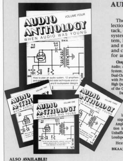
AUDIO ANTHOLOGY, Volume Four Edited by C.G. McProud The 34 articles from 1955-1957 in this fourth collection from Audio Engineering magazine take a new tack, emphasizing an overall view of the home sound system and offering guidance on how to plan a sys tem, how to keep it simple, and how to understand and maintain the equipment. Solid state techniques and circuits are introduced here, along with designs for amplifiers and preamps and 6 loudspeakers.
Chapters include: How to Plan Your Hi-Fi System; System Simplicity for Audio; Adequate Audio Power in the Home; Building Simplicity into the Hi-Fi System; The Care and Treatment of Feedback Audio Amplifiers; High Quality A Dual-Channel Amplifier; Stereo Monaural Companion Amplifier for the ''Preamp a old state techniques and cir- | with Presence'' [Volume Three]; Stereosonic Magnetic Recording Amplifier; and loudspeaker designed High Quality Treble Amplifier; Amplifier Uses Cheap Output Transformer; Effect Za of the Cathode Capacitor on Push-Pull Output Stages; What's All This About Damping?; Electrical Adjustments in Fitting a New Output Transformer;
Which Tube Shall I Use?; Understanding Intermodulation Distortion;
The Sad Tale of a Half-Watt Resistor; Compensation for Amplitude Responsive Phono Pickups; A Versatile Bass-Treble Tone Control; Record Speed and Playing Time; Recording Characteristic Simulator; Transistor Action; Transistor Preamps; Transistor Tips and Techniques; Transistor Preamp for Low-Output Pickups; A Transistor Playback Amplifier; Transistor Tone Control Circuits; A Transistor VU Meter; Distortion in Tape Recording; A Time Delay Commercial Suppressor; Baffles Unbaffled; Ported Loudspeaker Cabinets; The ''CW Horn'; The Aperiodic Loudspeaker Enclosure; and The Standard Speaker System.
Heavily illustrated. 1957, 1991, 144pp., 8 x 2 x 11, softbound.
ALSO AVAILABLE! YES! Please send me Audio Anthology, Volume One (1947-50) Audio Anthology, Volume Two (1950-52) Audio Anthology, Volume Three (1952-55) Choose any 3 volumes, at a savings of $8.95! Complete 4-volume set, at a savings of $12.85! .... Please circle the books you have ordered: Vol. 1 Vol. 2 Vol. 3 Vol.
++++++++++++++++
Also see: