Departments
- About this Issue
- JUST LOOKING
- EDITORIAL--My Test Tracks
- BOOK REVIEW--The Joy of Audio Electronics
- LETTERS
- NEW CHIPS ON THE BLOCK--BURR-BROWN INA-148
About this Issue
Readers who recall the Super Regulators series published over five years ago know the fundamental importance of the power supply in circuit design. This series generated much reader interest, and now we present an update to this work by Walt Jung ("Improved Positive/Negative Regulators," p. 8).
Frank Mee offers construction plans to build an AC power line monitor, which readers will find very helpful in their audio work to check voltage level ("An AC Power-Line Monitor," p. 20).
Much misunderstanding surrounds the principles of tonearms. Here, in terms you can easily follow, Dick Pierce attempts to clarify the confusion ("On the Mechanics of Tonearms," p. 24).
School's out for the summer, so Dr. Norman E. Thagard has concluded his six-part tutorial on 40W amp design just in time. He cautions that no matter how well-thought-out your design is, you can undermine your efforts with shoddy construction and poor layout, and addresses these two critical factors to ensure pleasing results ("A Case Study in Audio Amp Design," p. 30).
Charles Hansen dons his reviewer's cap to examine the Velleman PCS64i in the second part of his review of digital storage oscilloscopes ("Product Review," p. 36), while Gary Galo reviews a couple of products that will restore your damaged CDs ("Product Review," p. 42).
Be sure to check out our review of a new book for audio beginners, "Joy of Audio Electronics" ("Book Review," p. 46). Also, we are pleased to introduce a new feature by regular contributor Charles Hansen, who each issue will take a look at the latest audio ICs from the major chip manufacturers ("New Chips on the Block," p. 54).
JUST LOOKING
RESISTORS
Caddock Electronics offers a line of high voltage resistors for your electronics needs. You can select from a variety of non-inductive" models with low capacitance. For more information, or for our copy of the current edition of the Caddock general catalog-with specs on over 250 models of high-performance resistor products-contact Caddock Electronics, 1717 Chicago Ave., Riverside, CA 92507, 909-788-1700, FAX 909-369-1151, E-mail caddock@ caddock.com.
INTERCONNECT SOLUTION
The ISO-MAX Audio/Video Isolator Kit is he latest product from Jensen Transformers to eliminate hum and buzz n audio and video systems. The ISO MAX kit includes a two-channel audio isolator, composite video isolator, and CATV isolator, as well as a pair of BNC o-RCA adapters, a pair of diagnostic test adapters, and a troubleshooting guide. The product, aimed primarily at hose who install and service audio and video systems, comes in a rugged case designed for portability. Jensen Transformers, Inc., 7135 Hayvenhurst Ave., Van Nuys, CA 91406, 818-374 5857, FAX 818-7663-4574, www.jensen transformers.com.
SYSTEM SAFEGUARD, J. JENSEN Telecom
NEW RELEASES
Prompt Publications has recently released its 2000 Technical Book Catalog. This listing of over 200 titles, covering a variety of electronics related topics, is available free from 800-428 SAMS.
Prompt Publications has also released a collection of 30 electronics projects using surface-mount devices. SMD Electronic Projects, authored by Homer Davidson, includes parts lists, schematics, wiring hookups, board layouts, photos, and drawings to illustrate each project.
Jensen Tools has recently released a new catalog designed for the telecom, electrical, and global communications industries. It features a wide range of tool kits, hand and specialty tools, cable, telephone and electrical test equipment, and service aids. Jensen Tools, Inc.,
7815 S. 46th St., Phoenix, AZ 85044, 800-426-1194, FAX 800-366-9662, E-mail jensen@ stanleyworks.com, www.jensentools.com.
The Speaker Knife-II offers protection for your loudspeaker and amp equipment. This adjustable high-speed transient/overload protector prevents damage due to lightning-speed transients, excursion power overload, and amp failure, with the ability to instantly reset once the fault is corrected. Suitable for all driver types plus crossovers. For more information, contact Dynastar Electronics, 1531 E. Starpass Drive, Fresno, CA 93720, Phone/FAX 559-433-9700 E-mail dynastar@lightspeed.net.
EDITORIAL
My Test Tracks
I suspect nearly every serious audiophile has a collection of favorite, familiar music selections which he or she pulls out with nervous anticipation every time a new system component is installed.
There's nothing quite like the satisfaction of settling into the sweet-spot chair and leaning back for the first clear, familiar notes of that selected track. These special favorites collect over the years. I can still recall vividly the first time I heard Hermann Scherchen conduct L'Orchestre de la Suisse Romande in Rimsky Korsakov's "Russian Easter Overture," on a West minster LP. Those first five descending notes still sound in my ear when I recall that moment years ago.
We listen for the change in the sound, a new clarity, a new quietness, an absence of something that was there before. Maybe the hum is less audible, the mids cleaner, the lows more solid and authoritative.
Then a kind of frenzy starts. The excitement of the first sample sends you scurrying to pull out the next familiar favorite track to confirm that the changes are real, and the recorded samples sound better than ever. The evening wears on into the night and you have a growing excitement because you are hearing things on these CDs or LPs that you haven't heard before. They obviously have been on the disks all this time, but your system, up to now, simply had not unveiled them for you.
You develop a raging hunger to run through less-familiar pieces to hear what you have, until now, been missing in listening to your collection. It all seems like musical archaeology, or like a tour into undiscovered landscapes.
In the course of time, most of us have compiled a list of definitive tracks which show off some special capability of a music reproduction system. These often include a really fine solo piano disc by a master pianist. One of my favorites is an especially fine rendition of Brahms' "Hungarian Dance No. 3" (Brahms, Johannes, Hungarian Dance No. 3, Track 8, DGG, D101694, Gar diner, North German Radio Orchestra, 1993), whose tympani catches you by surprise, or parts of Prokofiev's oft recorded "Peter and the Wolf," where instruments literally float in etched ac curacy between the speakers. This same precision often occurs in out standing performances of Britten's "Instruments of the Orchestra"-his clever set of variations on a theme of Henry Purcell is usually more than a little revealing of a system's capabilities. (Brit ten, Benjamin, Young Person's Guide to the Orchestra, Variations and Fugue on a theme of Purcell; Track 1, EMI CDC 7 493002, Marriner: Minnesota Orchestra, 1984.)
I have learned over the years that many of our authors regularly keep a set of test favorites with which they have become very familiar, allowing them to make critical comparisons of any changes in response or characteristics when substituting some new component. I commend this practice to any serious audiophile as a way of keeping track of the evolution of his or her system.
[ can highly recommend the newest test disk from Hi-Fi News & Record Review, Disk III. I have chosen it as the source for seven tracks of wonderfully recorded music of a wide variety as ideal for putting equipment through its paces.
These tracks will be used by our review teams for the upcoming series of reviews in Glass Audio and eventually in Audio Electronics and Speaker Builder. These include selections from Parry, Purcell, Vivaldi, Prokofiev, and others. The disk contains a total of 74 tracks, containing test frequencies at a number of levels.
There's a stereo "Walkround" as well as novelties such as an automatic garage door and a dawn chorus of birdsong. A valuable addition to any audiophile's tools for keeping the system in good operating order.
What about your favorite test tracks? How about sharing your choices with others? Pick your favorite seven, describe them in paragraphs for each, not exceeding a total of 1000 words (four double spaced typed pages), including the names of the music, composer, manufacturer, and manufacturer's number. Send them to "Test Tracks," Audio Amateur Inc., Box 876, Peterborough, NH 03458, or e-mail them as an attachment to a note with your mailing address to editorial@audioXpress.com. If we choose yours for publication, we'll send you a $100 gift certificate from Tower Records, or, if you prefer, from our Old Colony Sound Lab catalog.
Share your favorites with others, and enrich your music collection at the same time.
-ETD
JFETS ULTRA LOW NOISE LS843 - 3nV/Hz typ
-_ TIGHTMATCHING LS843 - 1 mVmax
Custom Screening Die, SMT, Thru-Hole No Order Minimum COD's Accepted
-_- Second Source for mest
& Foreign JFETs & Bipolars
SHOWCASE
Pass Thagard A75-- Calgary Version
My version of the Pass/Thagard A75 (TAA 4/92, 1/93) has an all aluminum chassis. I mounted the Hammond 550W toroidal transformer and other power supply components on the base (Photo 1). Slots on the bottom allow air to circulate around the transformer and cool the rectifiers. I mounted two small fans in the top of the amplifier to complete the case (Photo 2).
I used a hacksaw and 4" hand-held drill to build the en tire chassis. This was the hardest part of the whole project; I am still picking bits of aluminum out of the carpet. I took Hammond at its word that toroidal transformers don't radiate. I mounted the transformer bare with no pot. It does not hum.
The 50V regulated power supply sits between the capacitors for the 40V unregulated supply (Photo 3). It is mechanically fastened by the same bolt that holds the transformer. (I'm impressed by really neat wiring, but seldom achieve it myself.) The driver section of the A75 mounts on the top frame of the chassis (Photo 4). Together with the post which holds the input and output connections, you can remove it and operate it independently (I needed to be able to separate it from the power supply in case I had to troubleshoot any AC hum).
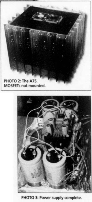
PHOTO 2: The A75. MOSFETs not mounted. PHOTO 3: Power supply complete.
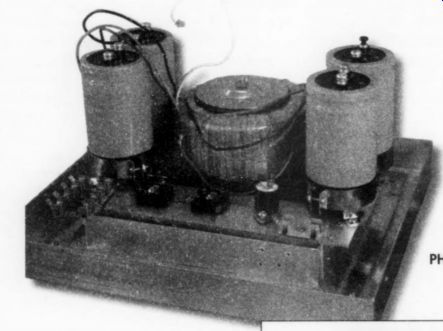
PHOTO 1: Bare frame.
Although not shown here, the first two output MOSFETs for each channel are also mounted on the post. I began building the amplifier using only the first out put pair on each side, wrapping the rest of the output stage around the case later.
I bolted some homemade heatsinks to the driver stage MOSFETs. When I finished everything else, I used Crazy Glue to affix a coffee stir stick across the top of them to stop any vibration.
I drew the circuit boards by hand using a resist crayon. This seems to be an extremely uncritical design and is unaffected by my "artistic" interpretation of the original board layout. The board shown in Photo 5 is nearly finished, missing only input pairs on both channels.
I mounted the heatsinks for the out put stage around the outside of the case, which is shown fitted and assembled without MOSFETs in Photo 1. Note the fans in the top plate scavenged out of a couple of old 486 computers that could not make the Y2K cut. I have since moved these fans to the bottom of the case to blow air in from the bottom. I found that the top-mounted fans pre vented the driver card from warming up evenly.
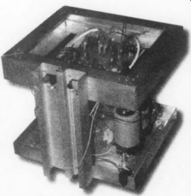
Photo 4. Upper part of frame.

PHOTO 5. Upper part of frame; PHOTO 6: The back of the A75.
Photo 6 shows the post at the back of the A75 with input/output connectors. This design offers 2000 in^2 of surface area and a lot of thermal mass.
It seems to shed heat well. Operating tempera ture rises to 50°C and doesn't rise more than a couple of degrees when the volume is turned up...and I do turn it up. At some point I will try it without the top cover and fans to see whether convection alone will cool it.
Later, I mounted the output MOSFETs using small boards that hold the source and gate resistors. You can assemble each side and test the unit before mounting on the case (Photo 7). As Vlatko Crvic pointed out in his article ("Building the A-75 on a Kitchen Table," AE 4/99, p. 34), drilling all the mounting holes is a real chore (nearly 500 precisely placed holes to mount the 48 output MOSFETs and heatsinks on this amp).
The output devices are matched sets of IRF 130 and 9130 MOSFETs. The even heating of the output MOSFETs at start up suggests that bias current is fairly consistent within these sets of 12 MOS FETs. The linear layout of the output makes me think that the next version of this amp I build will be a flat, wall mounted unit.
The finished amplifier has internal dimensions of 12" x 13" x 12". The fins on the heatsinks add another two inches to … still sounding fine) …. at the bottom of the picture. I will eventually place the A75 at the bottom of the stand behind glass to keep folks from touching it.
The sound quality on this amp is exceptional. Music is nicely de fined, with solid stereo image and a depth that some of my friends com pare to Sugden or Quad. I'm certainly impressed.
Thanks to Nelson Pass and Norm Thagard for designing this unit and making it available. Thanks to Audio Amateur/Audio Electronics for publishing the original articles describing this amp, and PassLabs for keeping it posted on their website.
Thanks to Ranger Audio, Calgary, for final adjustment and testing.
Julian Evetts Calgary, Alberta Canada
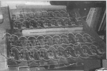
PHOTO 7: Output stage-wired.
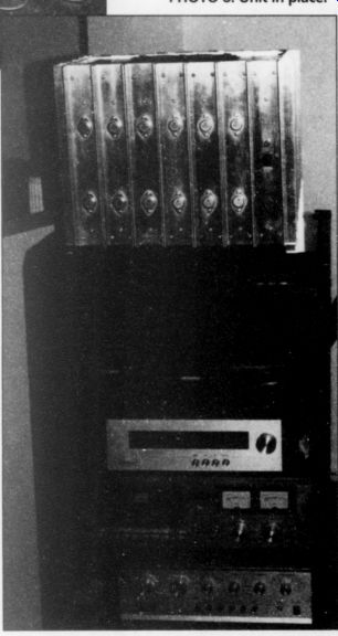
PHOTO 8: Unit in place.
BOOK REVIEW
The Joy of Audio Electronics
Reviewed by Bill Chater
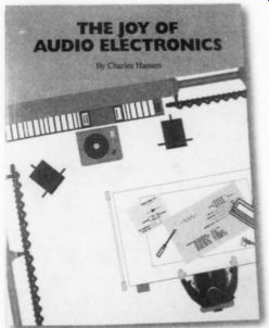
The Joy of Audio Electronics, by Charles Hansen. Available from Old Colony Sound Lab, PO Box 876, Peterborough, NH 03458
When it comes to hobbies, there can be few that combine such an interesting pair of enterprises as does an interest in audio, because it fuses the very technical with the very artistic-something about right-brain/left-brain comes to mind in this. Certainly there is great satisfaction in building with your hands an instrument that is to a certain extent unique- and thus not trivial-and at the same time you can get another level of satisfaction, for the instrument makes it possible to enjoy your favorite music, whatever form that might take. Thus you can feel like a craftsperson, as well as artistic.
If that is the base of your interest in audio electronics, to the uninitiated it can be discouraging. Like a lot of other pas times, it needs a certain level of under standing before you can play the game.
The fact that there are so many books "for dummies" tells us that there is a large audience in need of help in many subjects, and this is where you can appreciate the book Mr. Hansen has written.
But this book is not for "dummies," even though it is pitched to the beginner.
If you have ever wished to try your hand at the actual construction of something electronic, audio is a good place to start.
It is presumed at the outset that you have some knowledge you may not even know you have, for, by now many have experienced the challenges of coming up to speed with the modern computer, and have needed to learn a few things electrical, such as voltage and current, power and speed in an electronic sense, and many other words that have become part of the modern vernacular. In this book, concepts like these are used and described in context.
First Project
For some hands-on learning, start with Chapter One, which contains a simple, build-it-yourself project of a practical utility, fully described, with a lot of emphasis on the basics that a beginner might encounter. At some point in the text, though, the author has fallen into a trap of his own making, since there are some things that might first need explanation.
It is harder than you might think to intro duce a new-or nearly new-subject like this from the very beginning. In the manner of many tale-tellers, it is easy to forget that some item of importance to the tale has been left until later for description.
This is a familiar trouble, like the person who spills the punch line in a joke be fore telling the first part.
Therefore, it might be desirable to look over Chapter Four first to see what you are getting into, and how to actually build the Chapter One project. And maybe even before that, it is probably necessary to delve into Chapter Six's look at theory to find the descriptions of several electrical terms that are used (you guessed it) in Chapter One. A glossary of terms in a prominent place would have been nice for the beginner, to refer to as part of the rest of the text. This would have saved the reader from having to make a list along the way. For example, what is actually meant by the terms Q, CR, npn, LED? Or oscillation, or "hum?" These are basic terms, and demand an understanding (or a skip-over until later).
Mr. Hansen has managed a way through these small minefields, and of course many readers might take all this in stride. Beginners will have a chance to work it out as they go.
Second Project Once you get past these hurdles, Chapter Two opens up the subject of construction to a more complete and functional project, the so-called "Quadpod." Here we find an almost Heathkit-like thorough ness in how-to detail. Heathkit is a name many remember fondly as their own introduction to electronic kits. Newer readers must do without this now-historic experience, but will probably get the same results here in Chapter Two. I hope Mr. Hansen is flattered by the association. He is meant to be.
The Quadpod project provides the reader with a 32-page description of the construction of a piece of electronic equipment that brings together several hands-on projects. First, there is the mechanical construction of a chassis box to house the unit and make it attractive and useful in operation. Then, there is the assembly of the printed circuit board (not provided; however it is available from the publisher). This procedure introduces the builder to the physical nature of electronic parts, as well as soldering them in place.
There is that moment-of-truth experience when you turn it on for the first time, and in a sense get your examination grade for your work. By the time you are through with this business, you will very well be able to realize what goes on inside all electronic equipment, and you may wonder how it is that so much high tech equipment can actually be sold for so little. There is a lot of work and knowledge in it.
The rest of The Joy of Audio Electronics supplies a wealth of information, exhaustively compiled, about parts, retailers, and reference materials.
This part of the book alone took a lot of Mr. Hansen's attention, and will ensure that the book has a place on your shelf for regular reference.
Last, and maybe also least, I did find a few confusing typos-equation 6.34 on page 108 contains some errors (the gain is correctly calculated only for the part of the circuit following resistor R4, and the input resistance is not R2 for the circuit shown). Page 7 uses the capital omega for ohms, where instead the text must have meant a capital W for watts, while on page 9 the capital omega for ohms is needed instead of the W (two places) These small items can be easily corrected except for the possible turmoil they might cause in the mind of a beginner.
I wonder if Mr. Hansen has any more up his sleeve? Maybe there is an interest in "Project Three." We can hope for a second edition.
LETTERS
Addendum
Regarding the letter entitled "Op Amp Improvements," AE 3/00, pp. 47-48, the URLs referenced at the end of my response changed after I submitted it.
You can find a complete list of "Walt's Tools and Tips" columns (including those of the four audio op amps) at this URL: http://www.elecdesign.com/ magazine/jung.shtml.
Walt Jung Fallston, MD
Power Meter Redux
I just received e-mails from G.R. Koonce and from a friend in the space power (as in satellites) business regarding my Audio Power Meter article (AE 3/00, p. 6). Let me start by apologizing for using the term "RMS" power! There is instantaneous power or average power, but not RMS power. Every real power measurement I have made is average power,
P_avg = El cos = theta.
My power-meter project, with the DC component blocking cap between the analog multiplier and the RMS-DC converter, is really a VA meter, reading real power with resistive loads only, and is waveform sensitive, as I mentioned.
I meant it to be a piece of test equipment, not to be used for real time music power displays. We are all familiar with the "power" meters (like on the McIntosh amps) that actually display output voltage measurements on a log scale. The analog multiplier lets me use a linear meter scale.
I use my power meter to monitor the point where the THD reaches 1% (or 3% for tube gear) as the clipping power level. Some amps tend to fold back power, or suddenly jump in THD, at the max power point, and I can't switch from THD to voltage measurement and back fast enough on my distortion test set to pin down the exact point.
In my career in electric power, I de signed a number of power-protection circuits that used either E2/R or I?R, using the early analog multiplier ICs. I designed similar overcurrent protection circuits with inverse time delays (I't, to simulate thermal breaker time-delay curves) the same way.
G.R. did not see what the RMS-DC converter does for me. Blocking the DC component from the analog multiplier to the RMS-DC converter makes the approximation that
[sin(ot) x sin(wt)] = a constant times [cos(2mt)],
which is not a good one. This may be why the meter is accurate only for sinusoidal wave forms as indicated in testing with other waveforms. He thought the RMS converter is probably simply being used as the averager, since with sine-wave in puts it always sees the same input wave shape. I'm inclined to agree with him that an integrator circuit after the multi plier would work fine. It would probably be slower, being constrained by the low-frequency end of the wide audio bandwidth.
After I sent in the article, I thought that it might have been better to use two RMS-DC converters ahead of the multiplier-one for V and one for I. It would still be a VA meter, but the sensitivity to waveform might go away.
Charles Hansen; Ocean, NJ
Readers might wish to consider using the AD536A, which is about half the price of the ADG6G37, in Charles Hansen's "Audio Power Meter." It is not, however, a pin for-pin-compatible part. While the AD530A is less accurate, this disadvantage would appear to be minimal, given that an analog panel meter is used for the display. The RMS converters from Analog make measuring AC a breeze, and they do save real estate.
Jack Walton; Short Hills, NJ
Charles Hansen responds:
Mr. Walton is correct. The AD536] is used in the true-RMS voltmeter portion of the HP339A distortion test set (and the HP3400 series of true RMS voltmeters, if memory serves me right). The AD637 would be better if you intend to use the digital readout signal described in the article.
An Exacting Formula
I wish to comment on Raymond Futrell's letter entitled "Misleading" (AE 3/00, p. 49). I checked every electronics text that I own (some 20). About half, including one based on tubes and published in 1957, give a common-mode gain expression similar to the one that constitutes his "pet peeve." Not one gives the expression that he offers. Is this a situation, then, in which Mr. Futrell is smart and the rest of us, including a number of textbook authors, are stupid? I think not.
Most transistor designers learn early on that basing designs on exact transistor parameters is a poor technique. Tube de signers could rely on tube parameters that varied only about 5% for a given tube type from a particular manufacturer and perhaps 10% for a given tube type from different manufacturers. In that case, using tube parameters and plotting load lines made sense. Despite this, it is interesting that even the aforementioned tube based textbook offers an expression for the common-mode gain that involves the plate load resistor RL, as well as the plate resistance RP, after making exactly the same kind of approximations that transistor electronics textbook authors use.
Transistor parameters, to the contrary, are wildly variable. Transistor current gain (beta) can vary over a five- or even ten-fold range for the very same type small-signal transistor from the same manufacturer. Transistor output resistance RO is seldom given and must be inferred from the transistor curves; you are lucky if the manufacturer even provides these curves in the data book. Given this, how reasonable is it to expect a designer to use an exact formula requiring precise knowledge of beta and RO such as the one Mr. Futrell offers? About the only thing that using Mr. Futrell’s expression offers is frustration, since the designer must buy the transistors that will be used and then determine from measurement their actual parameters. From there, you could then, theoretically, calculate the necessary value of emitter or source resistor. Of course, if you ever need to replace either transistor, stand by to repeat the whole process.
I think I'll just be happy using the approximate formula in my ignorance and effect a pretty good design nonetheless.
After all, I currently have an amplifier of my own design and construction in my sound system that has a CMRR of over 60dB at 20kHz. Not too shabby, if I do say so myself.
Did I mention that to achieve this, I still had to adjust a trimmer resistor and a trimmer capacitor? Should I have done the precise design using Mr. Futrell's formula, I would still have needed to adjust the trimmers to maximize the CMRR, and I really doubt that the maximum CMRR achieved would have been significantly higher, at least not high enough to justify the effort. The precise formula would have bought me little besides additional (unnecessary) work.
Of course, authors (and designers) use approximations. It is inherent in the art of engineering that practitioners must know when and what approximations are appropriate in a given situation. Real world practical designers cannot afford to do otherwise.
My pet peeves are more on the order of dictators and environmental disasters due to negligence. People who write mildly offensive letters to the editor constitute for me at most a very minor peeve.
Norman Thagard; Tallahassee, FL
In Theory
I very much enjoyed Douglas Self's articles on distortion in audio power amplifiers (AE 2-4/99). His investigation into the causes of distortion should be required reading for design engineers.
I was wondering whether Mr. Self has ever tried to null the differential amplifier common-mode (CM) gain and third harmonic distortion by adjusting the tail resistance and bias current? Theoretically, this is possible.
It is commonly believed that the common-mode gain is proportional to the ratio of the load resistor to the tail resistor. I have seen this stated in textbooks.
If this is correct, then to obtain zero common-mode gain, or equivalently, infinite-common mode rejection, either the load resistor must be zero or the tail resistor must be infinite. This is, of course, impractical and also untrue.
Many years ago I was involved in the design of low-noise RF amplifiers. We used Y-parameters to characterize the transistors, because Y-parameters accounted for the parasitic elements and allowed a relatively simple design process. Using Y-parameter notation, the gain of an amplifier is given by the following formula
\! GAIN=-2= \ GY dety ij ) GG, + Yi +Y 12+ Yo, + Yoo Ht GeYaa +deryy)
where G, is the load conductor (inverse of load resistor) and G,. is the emitter con ductor. Obviously, for zero gain you set Y2, Je in the numerator of the formula.
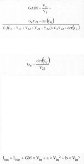
Converted to common emitter H-parameters, this becomes quite simply, G,_ = H,,/H,, or equivalently, R. =R_ x B. R_ is the emitter resistor, R is the transistor output resistance, and B is the transistor current gain. For a small signal transistor, R, is on the order of 100k-ohm at IMA collector current, and J is on the order of 100. R, is then on the order of 10M-ohm, a large but definitely not infinite resistance.
We would also characterize transistors by their transfer characteristic, given by the following expression
I I x GM X Vi, tax v.: ¥ b » Vin' out ~ "bias a and b are small numbers that account for the second-order and third-order curvature of the transfer characteristic. Normally we would try to bias the transistor to the most linear portion of the transfer characteristic to minimize distortion.
For best mixer operation, the transistor was biased at the bottom of the second-order (parabolic) curvature. We also found that when the transistor was biased at the inflection point of the third-order curvature, the third-order distortion would null. I have seen this effect only mentioned once in the literature, and it seems practically unknown to engineers.
We tried to exploit this effect, but the null was quite sharp, and if the quiescent current drifted 50uA, you were well out of the null. Since we ran the transistors at about 2mA, this meant that a 2% drift in the operating point moved you out of the null. We tried regulated bias and power supplies, but quit when we realized that the power supplies were more expensive than the RF amplifier. Not very cost effective.
It might be relatively easy to exploit these effects in a differential amplifier, because it already has a stabilized tail current source for bias, so little or no additional circuitry should be required.
Raymond A. Futrell Great Falls, VA
Douglas Self responds:
I thank Mr. Futrell for his kind words about my articles. I have not tried to null CM gain or third-harmonic distortion because it is not theoretically possible. Once the input pair is balanced for Ic, there are no more variables to tweak. Certainly the tail current cannot be used to null anything, It is indeed commonly believed that CM gain is tail-resistor/load resistor; in fact, I believe it myself. The argument that this cannot be right because it makes infinite CMRR impossible makes no sense to me. Infinite anything is impossible in a circuit anyway.
The rest of the letter does not, I'm afraid, appear to have any useful application to audio.
The biasing of RF mixers does not seer to be relevant to amplifiers.
In Search Of Tiger
I subscribed to The Audio Amateur when it first began in the '70s. I have several Tigersaurus amplifiers I built back then, but I don't know what happened to the schematics. Where could I find an other one? Mark McKelvey green@linkline.com The pages of The Audio Amateur have reflected readers' interest in this amp. Perhaps one of our readers can help. In the meantime, refer to Benjamin Poehland's "Taming the Flaming Tyger" (TAA 1/90, p. 26) and Walt Jung's Test Report in TAA 2/80, p. 43.
-Eds.
A40M Parts
I am enjoying Dr. Thagard's series on the A40M ("A Case Study in Audio Amp Design," AE 5/99-4/00), and am hoping to build my own unit this fall. I have some comments:
1. I have started to gather parts and thought I should let you know that the AH5020 analog switch is not just hard to find, but appears to be obsolete, as is the suggested replacement AH5012. 1 wonder whether Dr. Thagard will have a chance before the end of the series to advise of another replacement, or another set to replace the AH5020/2N5912 pair.
2. Also of note, the CR1 current source (listed in the text as 1N5283) and VR1 1.2V reference do not appear in the parts list. I haven't checked the list thoroughly; there may be other omissions.
3. One of my primary motivations to build this is the statement "...has served...since 1992 with zero failures." Nothing like a proven design.
My thanks to Dr. Thagard for publishing this series. It's giving me a taste of what it must have been like for science fiction fans to wait for the next installment of works like "Foundation." Paul Brown brownpau@telusplanet.net Norm Thagard responds:
First, I should like to thank Mr. Brown for his kind words. Such feedback is a large part of the satisfaction of authoring articles.
You could replace the n-channel/p-chan JFETs specified for the amplifier with the 25K389/25J109 Toshiba devices. I have recently used these transistors in a mm phono pre amplifier with good effect. Due to the significantly higher transconductance of the Toshiba J-FETs, it may be necessary to increase the value of compensation capacitor C2 to preclude oscillation.
I did not include the CR1 current source and the VR1 voltage reference in the parts list because, as discussed in the text of Part 2 there are some builder options regarding the specific components used. For example, Digi Key lists a number of different 1.2V reference in its catalog that are sourced by more than one manufacturer.
The amplifier is still being used as the surround amplifier of my A/V system, and it is still true that there have been zero failures. The closest thing to a failure occurred while a friend of mine was auditioning it during my stay on orbit soon after its completion in January 1992.
There was some arcing in the power supply be tween two board traces that I had obviously al lowed to run too closely together. Fortunately, the arcing vaporized the offending bit of copper, and not even a fuse was blown.
NEW CHIPS ON THE BLOCK
BURR-BROWN INA-148
By Charles Hansen
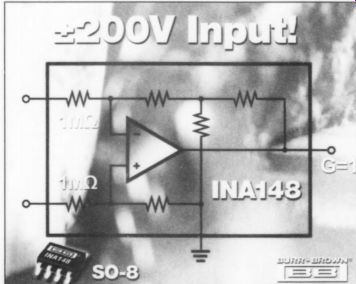
Burr-Brown has announced the new INA148 precision, low-power difference amplifier circuit that measures low-level signals in the presence of high common mode voltages (up to £200V). It is ideal for use in test equipment, power supplies, current shunt measurements in the pres ence of high-voltage systems, battery-powered systems, stacked-cell battery management, and automotive instrumentation.
The INA148 consists of a monolithic precision bipolar op amp with a thin film resistor network. The on-chip resistors are laser-trimmed for an accurate 1V/V differential gain and high common mode rejection. Excellent temperature tracking of the resistor network maintains high accuracy and common-mode rejection over -40°C to +85°C.
The INA148 features high common-mode voltage (+/- 200V with +/-15V DC supplies, +80, ~100V with +/- 5V DC supplies), low quiescent current (300uA max), wide supply range (2.7V to 36V single supply, +1.35V to +/-18V dual supply), low gain error (0.075% max), low nonlinearity (0.002% max), and high common mode rejection (70dB min).
The device has higher input impedance than any other difference amplifier on the market, which is extremely useful in minimizing leakage current drawn from the source or sensor. The INA148 is packaged in the SO-8 surface-mount.
For more information contact (800) 548-6132 or www.burr-brown.com; Burr-Brown Corp., PO Box 11400, Tucson, AZ 85734.
Also see: