The prime function of the radio-frequency (RF) voltage amplifier is to amplify the radio-frequency voltage which is already in existence in the grid portion of the circuit-in other words, to get a higher voltage at the same radio frequency in the plate circuit.
The radio-frequency band includes those frequencies lying within the broadcast band which extends from 540 to 1600 kilocycles per second. In addition, frequencies up to several hundred megacycles per second are also considered radio frequencies.
Pentode tubes are usually employed for RF amplifiers operating in the broadcast band and the simplest type of coupling between stages is impedance coupling. That is, a single coil is used, instead of a transformer between stages.
Sometimes the coupling circuit is made adjustable and tuned to an exact frequency. Then, signals at the desired frequency will receive most of the amplification and all other frequencies will be rejected. In other words, the RF amplifier selects a certain frequency for amplification. The degree to which this is accomplished is termed the selectivity of the circuit.
Often, it is more desirable to amplify all RF signals present at the grid. The gain and selectivity will not be as great, but the bandwidth, or range of frequencies amplified, will be greater in the untuned circuit used in this application.
UNTUNED IMPEDANCE-COUPLED AMPLIFIER
Figs. 1 and 2 show two half-cycles in the operation of a radio frequency voltage amplifier using untuned impedance coupling. The load circuit consists of radio-frequency choke coil L1. The various components of this circuit are:
R1-Grid driving and grid leakage resistor.
R2-Cathode biasing resistor.
R3-Screen-grid dropping resistor.
R4-Grid driving resistor for next stage.
C1-Cathode filter capacitor.
C2-Screen-grid filter capacitor.
C3-Coupling and blocking capacitor.
L1-Radio-frequency choke coil.
V1-Pentode amplifier tube.
V2-Next amplifier tube.
M1-Power supply.
The following currents are at work in this circuit:
1. Grid driving current (solid green).
2. Plate current (solid red).
3. Screen-grid current (solid blue).
4. Screen-grid filtering current ( dotted blue) .
5. Cathode filtering current (dotted red).
6. Amplified grid driving current for next stage ( dotted green).
Basically, this circuit and the ones discussed previously are alike in principle and function. As before, the grid is driven by causing an alternating current to flow up and down through the grid resistor. This grid driving current, usually called the signal current, flows at a radio-frequency rate in this example.
At an assumed frequency of 1,000 kilocycles per second, this grid driving current would make one million complete journeys down and up through the grid resistor, causing the grid voltage to change from negative to positive and back to negative this many times each second.
This varying control-grid voltage turns the plate-current stream through the tube down and up a million times a second. The resulting plate current flowing into radio-frequency choke L1 is a pulsating DC. The impedance of this choke coil is high enough that the pulsations of plate current cannot pass through the coil.
Instead most of them flow onto the left plate of coupling capacitor C3, driving electrons away from its right plate and downward through resistor R4. This situation, depicted in FIG. 2, is called the second half-cycle of operation.
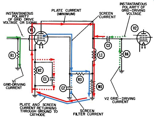
FIG. 1. Operation of the untuned impedance-coupled amplifier-first half-cycle.
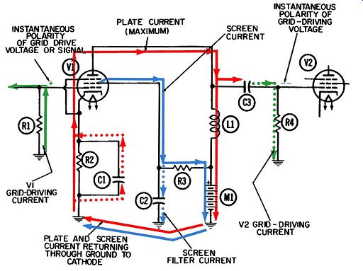
FIG. 2. Operation of the untuned impedance-coupled amplifier-second half-cycle.
During those periods between the pulses of plate current, this grid drive current for the next stage flows back upward through R4. The purpose of the tube stage is to amplify the input-signal voltage applied across resistor R1. This amplification cannot be accomplished unless the alternating voltage developed across R4 is significantly larger than the voltage across R1. If the voltage amplification (gain) achieved by this amplifier is equal to 50, then 50 times more alternating voltage will be developed across R4 than across R1. Should the two resistors have the same ohmic value, then the current flowing through R4 would also be 50 times greater than the current through R1.
The filtering of the pulses out of the plate current at the cathode, and out of the screen current by means of capacitor C2, are routine actions. Cathode filtering has already been adequately de scribed. Screen-grid filtering is of course required only with tetrodes or pentodes, which have the extra grid. On the second half-cycle (FIG. 2), when the number of electrons in the plate current stream increases, the number exiting from the tube via the screen grid will increase accordingly. If filter capacitor C2 were missing, this increase in screen current would cause a corresponding increase in the voltage drop across screen resistor R3.
As a result, the voltage at the screen would be lowered during these positive half-cycles.
During the negative half-cycles (FIG. 1), when the negative control grid reduces the number of electrons in the plate-current stream, the number exiting from the tube at the screen grid will be reduced accordingly. Without filter capacitor C2, this reduction in screen-grid current would cause a corresponding decrease in the voltage drop across resistor R3, and a resultant rise in the positive voltage applied to the screen grid.
These voltage changes at the screen grid are undesirable be cause they constitute a form of degeneration which reduces the available amplification from the circuit as a whole. The reason is that the screen-grid voltage has a definite effect on the amount of plate current through the tube. With this type of degeneration present, the voltages at the screen and control grids will be working at cross-purposes: As the control grid tries to increase the plate current, the screen grid will act to reduce it, and vice versa.
The resulting loss in amplification can be avoided by the addition of C2. This filter capacitor absorbs the pulses of screen cur rent during the positive half-cycles. The filter current (shown in dotted blue) is now driven from the lower plate of C2 to ground and permitted to return upward on the negative half-cycles.
With the audio circuits discussed in earlier Sections, filter connections were usually made directly to ground. When radio-frequency currents are being handled, cathode and screen filter capacitors should normally be connected to the lower end of the cathode resistor rather than directly to ground. Once the radio frequency currents are permitted to enter the common ground (usually the chassis), they could be coupled through it to some other point and introduce undesirable feedback there.
As is true with all vacuum-tube circuits, the plate and screen currents must eventually return to the cathode after passing through the load and power supply M1. This return path has been indicated beneath the diagrams.
As mentioned previously, a circuit using an untuned impedance as a load lacks the high selectivity of circuits with tuned loads (discussed later). It is this feature which gives rise to the use of this circuit, for there are applications where radio-frequency amplifiers in series can become too selective and pass too narrow a band of frequencies to carry the desired intelligence, or modulation. By using an occasional untuned impedance load like this one, the selectivity is broadened somewhat, but at the expense of gain.
TUNED IMPEDANCE-COUPLED AMPLIFIER
This pentode radio-frequency amplifier has a tuned circuit connected to the grid and another one in the plate circuit. These circuits are normally tuned to be resonant at the same radio frequency.
Figs. 3 and 4 depict the two half-cycles of the tuned impedance-coupled RF voltage amplifier. The various functions of this circuit, and the manner in which they are accomplished, will be discussed in detail in this section. The circuit components include:
R1-Grid resistor.
R2-Cathode biasing resistor.
R3-Screen-grid dropping resistor.
R4-Grid resistor for next tube.
C1-Grid tank capacitor.
C2-Grid coupling capacitor.
C3-Cathode filter capacitor.
C4-Screen-grid filter capacitor.
C5-Plate tank capacitor.
C6--Grid coupling capacitor for next tube.
L1-Grid tank coil.
L2-Plate tank coil.
V1-Pentode tube.
M1-Power supply.
There are three different groups, or "families," of currents at work in this circuit during normal operation. The first of these includes the radio-frequency alternating currents in the two tank circuits, together with their output currents and voltages. These have been shown in solid green in the grid circuit, and in blue in the plate circuit. The second family is made up of the unidirectional currents, shown in solid red, which flow primarily in one direction only; their paths are through the vacuum tube, and also through the power supply.
The third family consists of filtering currents ( one is shown in dotted red and the other in blue) flowing into and out of capacitors C3 and C4.
All these currents will have radio-frequency components-it should not be inferred that the ones labeled "radio-frequency alternating currents" are the only currents with RF components.
FIG. 3 shows the current flow and voltage polarities during the first half-cycle. It is labeled a "negative half-cycle" because the grid driving voltage becomes progressively more negative during this half-cycle, until at the end it reaches its most negative value.
FIG. 4 shows the current flow and voltage polarities during the second, "positive," half-cycle. During this half-cycle, the grid driving voltage becomes progressively more positive and at the end reaches its most positive value.
FIG. 5 shows the significant current and voltage waveforms which occur during circuit operation. Vertical lines have been drawn on the diagram to separate the half-cycles.
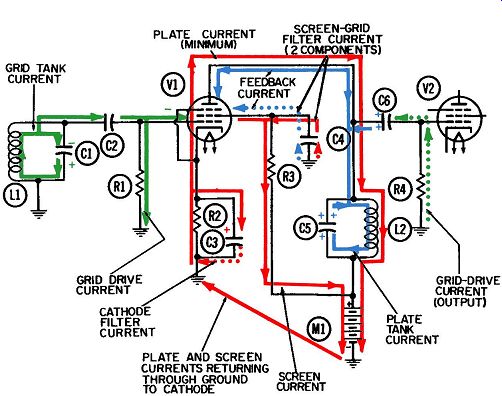
FIG. 3. Operation of the tuned impedance-coupled amplifier-first half cycle.
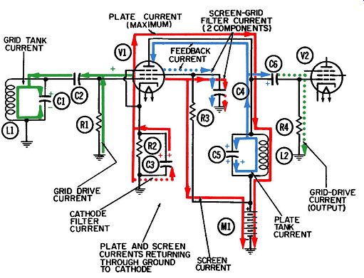
FIG. 4. Operation of the tuned impedance-coupled amplifier-second half-cycle.
RADIO-FREQUENCY ALTERNATING CURRENTS
FIG. 3, which depicts current conditions during an entire half cycle of radio frequency and the voltage conditions at the end of the half-cycle, shows electron current (in solid green) flowing upward through grid tank inductor L1 and charging the upper plate of grid tank capacitor C1 with electrons. The negative voltage created at this point causes electrons to flow onto one plate of coupling capacitor C2. An equal number are driven off the opposite plate and flow downward through grid resistor R1.
This electron flow is also shown in solid green.
The grid will have its maximum negative voltage at the same time this current is flowing downward through the grid resistor at its maximum rate. It will always help, in determining whether a grid is negative or positive, to remember that electrons always flow from negative to positive. Since they are flowing downward through the resistor, toward ground, this tells us the ground voltage is more positive than the voltage at the top of the resistor, which is connected to the grid.
Special attention should now be given to the waveforms for this circuit, in order that phase relationships between the various currents and voltages can be understood.
Grid tank current flows from the bottom plate to the top plate of capacitor C1 during the entire negative half-cycle and stops at the end of the half-cycle. In the waveform representing grid tank current in FIG. 5, that portion of the waveform below the center, or reference, line represents electrons flowing upward through tank inductor L1. Conversely, that portion above the reference line represents electron current flowing downward through L1.
At those points where the current waveform actually crosses the reference line--at the beginning and end of each half-cycle zero current in flowing. That is, electrons have stopped flowing in one direction, and have not yet started in the opposite direction.
In FIG. 5 we see that at the end of the negative half-cycle, when the upward electron flow through the tank inductor has been completed, the grid tank voltage shown in line 2 has reached its negative peak value. The reason is that the tank current has delivered the maximum concentration of electrons to the upper plate of capacitor C1.
Line 3 of FIG. 5 shows the direction and amount of the grid drive current, which is caused to flow by the tank voltage of line 2 and is "in phase" with this voltage. The grid drive current, in FIG. 3, flows downward through grid resistor R1. This current is also known as the tank circuit's "external current." As long as there is a negative charge, meaning negative voltage, on the upper plate of C1, this electron current will flow away from the negative charge ( or downward through the grid resistor) . When there is a positive charge, meaning positive voltage, on the upper plate of the tank capacitor, these electrons will be drawn toward this positive voltage and consequently, upward through the grid resistor.
The voltage developed across any resistor is always in phase with and proportional to the current through it.
Thus, the voltage developed across resistor R1 ( the grid driving voltage) will have its maximum negative value at the end of the negative half-cycle, when the tank's external current reaches its maximum downward flow. At the end of the positive half-cycle, when the external current achieves its maximum upward flow, the grid driving voltage will attain its maximum positive value.
Thus, the tank voltage and the grid driving voltage will be in phase with each other at all times.
V1 is being operated under what are called Class-A conditions.
That is, the tube conducts electrons during the entire cycle, as shown by the plate current waveform (line 4) of FIG. 5.
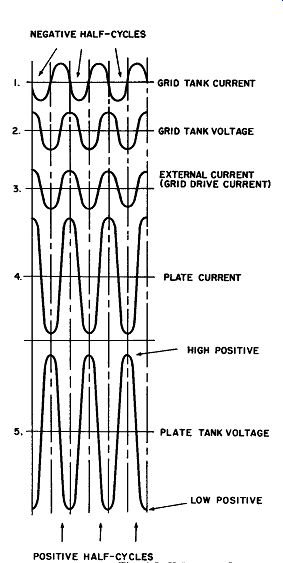
FIG. 5. Voltage and current waveforms in the tuned impedance-coupled amplifier.

FIG. 5b
Another RF alternating current is shown in the plate tank circuit-this time in solid blue. This plate tank current (which is oscillating continuously between capacitor C5 and inductor L2) consists of considerably more electrons than does the grid tank current. The plate tank current is actually an "amplified" version of the grid tank current.
The plate tank voltage, which is measured at the top of coil L2 and capacitor C5, is also an amplified version of the grid tank voltage.
This plate tank current supports two other currents, both shown in solid blue. One is the output current flowing in and out of capacitor C6. The other is the feedback current, which flows between the tank and the plate of the tube. Both act as "loads" on the electrons which are oscillating in the tank. During the last portion of the negative half-cycle and the first portion of the positive half-cycle, when the plate tank voltage is most positive, electrons are being drawn from the left plate of C6 and from the plate of the vacuum tube. This action draws electrons upward through grid-resistor R4 of the next tube and onto the right plate of C6. This flow of electrons (shown in dotted green), is the grid-driving current for the next tube. It will produce a positive voltage, with respect to ground, at the top of R4.
FILTERING CURRENTS
The function of the screen-grid, in helping to prevent a circuit from going into sell-sustained oscillations, can now be explained by reference to the feedback current.
The feedback current, shown in solid blue, is separate from the unidirectional plate current, shown in solid red. During the last portion of the first half-cycle, the electrons which make up the feedback current are being drawn away from the tube plate and toward tank circuit inductor L2. Their movement away from the tube plate draws electrons toward the screen grid from its external circuit. A filtering current ( dotted blue) therefore flows in the screen grid circuit. During the latter portion of the negative half-cycle and the first portion of the positive half-cycle, this filtering current is flowing upward from the top plate of C4 to the screen grid, and upward from ground to the lower plate of C4.
The screen grid and the plate of the tube act like two plates of a capacitor. The feedback current, which is driven by the oscillating plate tank voltage, in turn drives the filtering current along its path to ground through capacitor C4. If this screen grid were not in the tube, the feedback current would drive an un wanted current in the control grid circuit and the entire circuit could go into self-sustained oscillation. Both the control grid and the screen grid have interelectrode capacitance with respect to the plate of the tube. However, the screen grid is much closer to the plate, and therefore has much more capacitance to the plate, than does the control grid. Consequently, most of the energy represented by the feedback current is diverted harmlessly to ground, through filter capacitor C4 by means of the filtering current.
Additionally the wire mesh, which makes up the screen grid, shields the control-grid wires from the plate of the tube and thus greatly reduces the amount of interelectrode capacitance between control grid and plate.
C4 must do an additional filtering job-it must bypass to ground the fluctuations in the unidirectional screen grid current. The electron stream which flows through the vacuum tube consists of the part which goes to the plate and its external circuit, and the part which exists at the screen grid. The number of electrons in this stream is being continually varied by the changing voltage on the control grid. During the positive half-cycle (represented by FIG. 4), the control grid is made positive and a heavy surge of current goes through the tube. That portion which exists at the screen grid finds two alternate paths-it can flow directly into the screen-grid resistor, which is a comparatively high impedance; or it can flow momentarily onto the upper plate of capacitor C4.
A size of capacitor is chosen that will act as a comparatively low reactance (impedance) at the particular frequency. Consequently, the surge of electrons in the screen-grid current during the positive half-cycle flows into C4, driving an equal number of electrons from the lower plate of C4 as shown by the dotted-red lines. A half-cycle later, during the conditions depicted by FIG. 3, the screen-grid current is reduced considerably, and the excess electrons resting on C4 from the previous half-cycle will now be drawn off through the screen-grid resistor R3 and to the power supply. At the same time, electrons will flow upward from ground to the lower plate of C4. These electrons, shown in dotted red, are the filtering component for the unidirectional screen-grid cur rent. They of course are independent of the filtering current for the feedback energy previously described, even though they flow along the same path.
Resistor R2 and capacitor C3 function as an RC filter in much the same fashion as R3 and C4. All the unidirectional current which passes through V1 must first flow upward through R2 to reach the cathode. Since this current is constantly fluctuating (because of the voltage variations at the control grid), the amount of current through the resistor would also fluctuate if it were not for filter capacitor C3. If the current were allowed to fluctuate the voltage across R2 would also fluctuate, causing a normally undesirable condition known as degeneration.
During the period depicted by FIG. 3, the control-grid voltage has been made negative and the flow of electrons through the tube is thus restricted. The cathode is being held at a positive voltage by the deficiency of electrons (indicated by the red plus sign) on the upper plate of C3. This positive voltage will continue to attract electrons upward through resistor R2, and if the negative control grid prevents them from entering the tube, they will flow directly onto the upper plate of C3, as indicated by the red arrow. This action would tend to reduce the positive voltage in storage on the capacitor, and such reduction would be equivalent to a half-cycle of degeneration.
FIG. 4 indicates that the positive control grid increases the amount of electron current through the tube. This increased demand for electrons to leave the cathode may be supplied either through resistor R2 or capacitor C3. A size of capacitor is chosen that will have a reactance of a very few ohms at the operating frequency. Consequently, a sudden surge of electrons will be drawn into the tube from the upper plate of C3. This action will tend to increase the positive voltage on C3 ( and at the cathode of the tube) and thereby constitute another half-cycle of de generation.
The size of a capacitor (meaning its amount of capacitance) is paramount in determining whether such degeneration will occur, or whether it will be held within acceptable limits if it does.
As long as the "pool" of positive ions on the upper plate of capacitor C3 is overwhelmingly large, in comparison with the number of electrons coming into or going out of capacitor C3 on successive half-cycles, then the "pool" voltage will not change significantly from one half-cycle to another and degeneration will not occur.
The cathode filtering current is shown in dotted red between the lower plate of C3 and ground. It is moving downward during the first half-cycle, being driven by the influx of electrons onto the top plate of C3. During the second half-cycle, as electrons surge away from the upper plate and into the tube, the filtering current is drawn upward from ground and toward the lower plate. The free movement of this filtering current is essential to the filter function. If something prevented this current from flowing (say, a broken connection), then the fluctuations of cur rent onto and away from the top plate of C3 (shown in solid red) cannot occur. The electron flow through resistor R2 will then vary in unison with the variations in electron flow through the tube, and the resulting voltage across the resistor will also vary.
In other words, we would have degeneration.
The most obvious effect of degeneration is a decrease in the over-all amplification achieved by the circuit. This amplification is a comparison between the input and output voltages. The amount of output voltage in this figure is proportional to the number of electrons (shown in solid blue) oscillating in the plate tank circuit. The size of any plate tank oscillation will depend on the size, or strength, of the current or voltage which replenishes it each cycle. This oscillation is replenished by the variations in amount of unidirectional current which reaches the tank from the tube.
UNIDIRECTIONAL CURRENTS
FIG. 3 shows a negative voltage on the control grid, with the resulting decrease in the number of electrons through the tube.
If degeneration were occurring, this decrease in tube current through cathode resistor R2 would also decrease the positive voltage at the cathode. The difference in voltage between cathode and grid would not then be as great as desired, and the reduction in tube current from its normal value would not be as great as desired.
FIG. 4 shows a positive voltage on the control grid, with the resulting increase in the number of electrons going through the tube. If degeneration were occurring, this increase in tube cur rent through the cathode resistor would increase the positive voltage at the cathode. The difference in voltage between control grid and cathode again would not be as great as desired, and the increase in tube current flowing would not be as great as desired.
The plate tank oscillation is sustained by the surges in the unidirectional plate current. The size, or strength, of each surge is determined by the difference in the number of electrons flowing through the tube at these two moments (namely, at the grid voltage negative and positive peaks). Larger surges of electrons will sustain larger oscillations. As the surges become smaller, so will the oscillations. When degeneration is occurring, the mini mum current through the tube will not be low enough and the maximum current will not be great enough. As a result, their differences will be reduced and the plate tank oscillation will be smaller accordingly. The output voltage, which is directly proportional to the size of this oscillation, will also be reduced accordingly.
The total path of the unidirectional plate current (solid red) is a closed circuit which can be considered to originate and terminate at the ground connection below the cathode resistor. Normal vacuum-tube action includes a heated cathode which will emit electrons into the tube, and a positive voltage on the plate (anode) to attract the electrons across the tube. Once across the tube, they continue flowing toward the point of highest positive voltage--the point known as B+, or the power supply. Plate current flows through the power supply, entering at its positive terminal and exiting at its negative terminal, or ground. Once this cur rent is returned to a common ground, the condition of having a closed path for the plate current has been met.
When a varying grid voltage imposes fluctuations in the quantity of the current, as is done in this example, these fluctuations are available for sustaining the oscillation in the plate tank circuit.
The size of the current fluctuation determines the size of the tank oscillation which will be supported, each individual fluctuation replenishing and thus reinforcing an individual cycle of oscillation.
The ability of a vacuum tube to act as an amplifier stems from the fact that small changes in control-grid voltage will cause much larger changes in the amount of current which flows through the tube (plate current). These large fluctuations in plate current can then give the oscillations much greater voltage swings than they had in the grid circuit.
The second member of the "unidirectional tube-current family" is the current which exits from the tube via the screen-grid electrode ( also shown in solid red) . Going by the name of screen-grid current, it flows (in unison with the unidirectional plate current) upward through the cathode resistor and into the tube via the cathode. Because the screen grid is maintained at a high positive voltage, a substantial portion of the electrons passing through the tube are attracted to it. After striking the screen-grid wires, these electrons exit from the tube and are drawn through screen grid resistor R3, toward the point of highest positive voltage in the circuit (the entrance to the power supply). Their closed path is through the power supply and back to common ground.
If there were no fluctuations in the amount of over-all tube current, there would be no significant fluctuations in the amount of screen-grid current. (Such a condition is referred to as static operation of the tube.) The plate tank oscillation would not be sustained under these conditions. However, when the signal voltage is impressed at the grid circuit, the electron stream through the tube does fluctuate in quantity and the tube is said to be operating under dynamic conditions. The control-grid wires, through which this stream must pass, act like a control valve on this stream. A positive voltage at the grid turns the stream "up," by increasing the number of electrons that flow. This condition is depicted by FIG. 4, where plate current is maximum. A less positive (more negative) voltage at the control grid turns this stream "down," by reducing the number of electrons passing through the tube. This condition is depicted by FIG. 3, where plate current is minimum.
The manner in which capacitor C4 filters out these fluctuations in screen-grid current was described in the discussion on filtering currents, and will not be repeated here. The RC combination of R3 and C4 must be a "long time-constant" combination to the radio frequency in question, and the combination of R3 and C4 operates in much the same fashion as R2 and C3 in the cathode circuit. The filtering action assures that a steady rather than a fluctuating flow of electrons occurs in screen-grid resistor R3.
If this current were allowed to fluctuate, then the voltage across R3 would also fluctuate and vary the voltage at the screen grid accordingly, whereas the latter voltage should be constant. In other words, the screen-grid voltage would decrease whenever the tube current increased and vice versa. Thus, degeneration would be occurring, and the end result would be the same as when degeneration occurs in the cathode circuit-namely, a de crease in amplification.
This circuit is called a voltage amplifier. We are seeking to amplify the driving voltage applied to the control grid of the amplifier tube. This is the voltage developed across grid resistor R1 by the flow of grid driving current through R1. This grid drive voltage has the same value and phase as the grid tank voltage shown in line 2 of FIG. 5.
The plate tank voltage, represented by the plus signs on the upper plate of capacitor C5 in FIG. 3 and 4, alternates at the same frequency as the grid tank voltage, but its amplitude is much larger. The voltage value is, of course, directly related to the number of electrons in oscillation in the plate tank circuit. For these reasons, it is an "amplified" version of the grid tank and grid driving voltages.