There are three methods of using transformer coupling to amplify voltages at radio frequencies. They are: Untuned primary-tuned secondary.
Tuned primary-untuned secondary.
Tuned primary-tuned secondary (frequently called bandpass amplification). In the discussions that follow, the operation of these circuits will be explained in detail.
UNTUNED-PRIMARY-TUNED-SECONDARY COUPLING
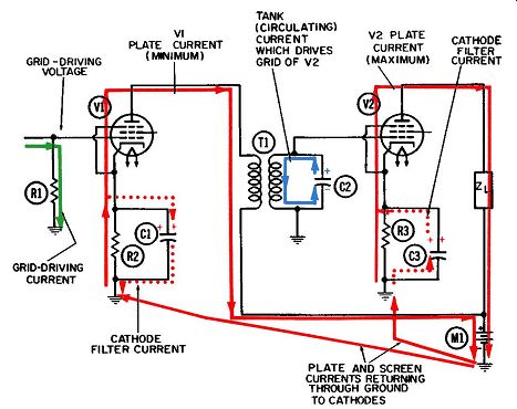
FIG. 1. Operation of the untuned-primary-tuned-secondary RF amplifier-first
half-cycle.
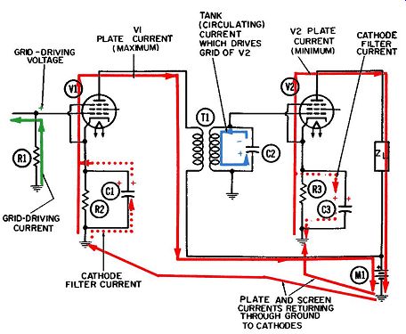
FIG. 2. Operation of the untuned-primary-tuned-secondary RF amplifier-second
half-cycle.
Between the first two variations given in the foregoing, the untuned primary-tuned secondary offers more advantages and hence enjoys wider usage. Figs. 1 and 2 show two successive half-cycles of such a circuit. Any tuned transformer coupling will introduce the problem of coupled impedance. The principles of coupled impedance apply equally to the first two examples given previously. In other words, it matters not which ·winding is tuned and which is not, as far as explaining the principles is concerned.
The elements for the circuit in Figs. 1 and 2 include:
R1-Grid driving and grid return resistor for V1.
R2-Cathode biasing resistor for V1.
R3-Cathode biasing resistor for V2.
C1-Cathode filter capacitor for V1.
C2-Tuning capacitor for secondary winding.
C3-Cathode filter capacitor for V2.
T1-Radio-frequency transformer.
Z1--Load circuit for second stage.
V1 and V2-Pentode amplifier tubes.
Ml-Common power supply for both stages.
Additionally, a screen-grid resistor and its filter capacitor are required for each pentode tube. Since screen-grid biasing and filtering were covered in the previous Section, these components and the currents which flow through them have been omitted from the circuit diagrams and also from the discussion which follows.
The remaining currents at work in this circuit appear in Figs. 1 and 2. They include:
1. Initial grid driving current or signal (green).
2. Plate current through both tubes (solid red).
3. Cathode filter currents for both tubes ( dotted red).
4. Oscillating tank current (blue). Notice, both tubes for this circuit are served by a common power supply, Ml. In actual practice, a single power supply normally supplies the B+ voltage to all tubes in the radio or television set. A B+ line is run through the set and every plate and screen grid requiring high positive voltage is tapped into it.
If we could look inside the B+ line, we would see a vast stream of electrons moving steadily toward the high-voltage terminal of the power supply. This electron stream is composed of all the plate currents and all the screen currents from all the tubes. It is drawn into the positive terminal of the power supply and through the power supply to common ground.
When the tank circuit, consisting of capacitor C2 and the trans former secondary winding, is tuned to the frequency of the pulsations in the plate current, the tank is said to be resonant at that frequency. In flowing through the primary winding, the pulses will induce a secondary current that lags the current through the primary winding by exactly 90°. The voltage produced by the secondary current will be in phase with the current when the tank is resonant at the applied frequency.
The secondary current will also induce a current in the primary winding. This current will lag the "inducing" current by another 90°; so it will be 180° out of phase with the original applied voltage in the primary. Also, this current induced by the secondary into the primary will have a companion voltage, also induced in the primary winding. These two, the primary induced current and voltage, will be in phase with each other but 180° out of phase with the original applied voltage and current.
Currents which are out of phase oppose each other and subtract from each other. Voltages do likewise.
In the example of an untuned primary winding and a tuned secondary winding that is exactly resonant at the frequency of applied current and voltage, the coupling between the two wind ings reduces the strength of the original applied current and voltage. In turn, the induced secondary current and voltage suffer the same fate.
Mathematically, the reduction in applied current and voltage in the primary is the result of coupled impedance-in other words, the impedance from the secondary is coupled back to the primary.
This sequence can be understood by relating the two currents and voltages to the tank current circulating in the tuned tank, and also to the tank voltage associated with this tank current.
We are in reality talking about four currents and four voltages on the two sides of the transformer.
FIG. 3 shows four successive quarter-cycles in this type of coupling circuit. The four currents are identified as follows:
1. Primary plate current (solid red).
2. Secondary induced current (dotted red).
3. Secondary tank current (solid blue).
4. Primary induced current ( dotted blue). The four voltage polarities are: "Applied" voltage in primary (red). Induced voltage in secondary (red).
Secondary tank voltage (blue).
Primary induced voltage (also known as counter emf), (blue).
By inspection of the four parts of FIG. 3, we see that at the end of each quarter-cycle, the applied plate current in the primary winding goes through its characteristic motions as follows:
1. It is decreasing at its maximum rate (FIG. 3A).
2. It has its minimum value (FIG. 3B).
3. It is increasing at its maximum rate (FIG. 3C).
4. It achieves its maximum value (FIG. 3D). We know that whenever pulsating DC (like this one) flows through one winding of a transformer, a current will be induced in the secondary winding, and this current will lag the primary current by 90°. We can observe this phenomenon in Fig. 4-11.
The primary current (plate current) reaches its minimum value at the end of the second quarter-cycle, but the induced voltage does not reach its maximum value until the end of the third quarter-cycle.
In FIG. 3D the plate current has reached its maximum value, whereas the voltage induced in the secondary winding does not reach its peak until 90° later, or at the end of the first quarter cycle shown in FIG. 3A. (D) fourth quarter-cycle.
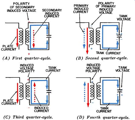
FIG. 3. The four quarter-cycles of operation of the tuned secondary circuit
at resonance.
On the other hand, the induced secondary voltage and current are in phase with each other. This means they achieve their peak values at the same instant as indicated in Figs. 3A and C. It is worth taking the time to understand why the induced voltage and current within the secondary winding are in phase with each other. One of our initial assumptions was that the tank circuit was tuned so it would be resonant at the frequency of the applied current. Part of the definition of resonance includes the stipulation that the inductive reactance and the capacitive reactance must be equal in value but opposite in polarity, so that they cancel each other. This means they "add up to zero" and the only remaining impedance is the insignificant resistance in the wire of the coil. Consequently, the induced current 'sees" only a low-resistance path within the tank and the current and voltage will be in phase.
Although the tank circuit, consisting of capacitor C2 and the secondary winding of transformer T1 in FIG. 1 and 2, is an example of parallel resonance as far as delivering an output voltage to the grid is concerned, the capacitor and secondary winding are in series to the induced current. This anomaly occurs frequently and can easily confuse you. However, the true criterion in determining whether components are in series or in parallel with each other is not the manner in which they are connected, but the path they present to certain currents. The tank circuit in this example is parallel-resonant to the external circuit to which it is connected, and series-resonant to currents flowing within the tank (the induced and circulating currents.) This point will be discussed further in the later example involving both a tuned primary and secondary winding.
We see from inspection of FIG. 3 that the induced current in the secondary winding is flowing in phase with the circulating current. The circulating current (also called the tank current)
is in reality an oscillation of electrons sustained by the induced current. With a tuned circuit having a reasonably high value of Q, a fairly substantial oscillation can be built up from a fairly small amount of sustaining energy.
The tank voltage and current are of course 90° out of phase with each other. A downward current peak is achieved at the end of the first quarter-cycle in FIG. 3A, but another quarter cycle is required before this current flow can deliver enough electrons to the lower plate of capacitor C2 to create a voltage peak. There will be a negative polarity on the bottom plate of C2, and a positive polarity (deficiency of electrons) on the upper plate. By this time the induced current has come to a halt. Like wise, an upward peak of electron current is achieved through the secondary winding at the end of the third quarter-cycle; but another quarter-cycle is required before this current flow can deliver enough electrons to the upper plate of C2 to create a negative voltage peak here.
It is a characteristic of a coupling transformer that its coupling works both ways-the primary current will induce a current and a companion voltage in the secondary winding; at the same time, the induced secondary current will itself induce a second current and companion voltage in the primary winding. In our example (FIG. 1 and 2) the pentode has a "plate resistance" of several hundred thousand ohms, which is very high. The total impedance of the primary circuit is essentially resistive, so the current and voltage induced in the primary winding will be in phase with each other. This means they will reach their peak maximum and minimum values at the same moment. These induced current and voltage peaks occur at the end of the second and fourth quarter-cycles. This happens to be 90'', or a quarter of a cycle, later than the peak values of the inducing current (the tank current). Thus, the voltage re-induced in the primary winding is essentially 180", or half a cycle, out of phase with the original (applied) voltage and thus reduces the effectiveness of the applied voltage. Accordingly, less current and voltage will be induced in the secondary winding than would be possible if the re-induced voltage did not exist.
FIG. 4 graphically illustrates the currents and voltages of FIG. 3. The currents shown above their reference lines are flowing upward through the coil, except for the plate current, which always flows downward as a pulsating DC.
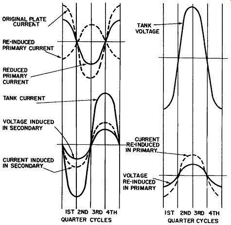
FIG. 4. Voltage and current waveforms in the tuned secondary circuit at
resonance.
The total current flowing in the primary winding is of course the sum of the primary plate current, plus the current induced in this winding by the circulating tank current. Since they are out of phase, the primary plate current is reduced by the amount of the induced current. It is convenient to think of this reduction in primary current as being caused by an additional impedance "coupled" into the primary winding from the secondary circuit, because impedances always change the amount of current flowing in a circuit (usually they reduce it-but not always, as we shall see in the following example). The amount of impedance coupled from one winding to the other, and the amounts of current and voltage induced in one winding by current in the other one, can be precisely calculated.
However, these calculations will not be elaborated upon here. Instead, we will take the opportunity to grasp some of the important terminology of coupled circuits-the degree of coupling, tight or loose coupling, coefficient of coupling, mutual coupling, and coupled impedance.
In an iron-core transformer like the one in audio-output or low-frequency power circuits, practically all the magnetic lines of force set up by a current through one winding will flow through the iron core and encircle or "link" the other winding. Under these circumstances, the degree, or coefficient of coupling between the two windings is practically unity.
Higher frequencies force us to use very small values of inductance, because inductive reactance increases as the frequency does. A coil designed for radio frequencies will consist of only a few turns of wire wound around an air core, and its inductance will be 100 to 200 microhenrys. Two such coils constitute a radio frequency transformer, and the coefficient of coupling between coils (represented by the symbol k) will be extremely low perhaps one or two per cent. With an air-core transformer, it is almost impossible to avoid a great amount of leakage flux (the term applied to magnetic lines of force which are set up by a current through one winding and which do not link the other winding). The mutual inductance between two coils, L1 and L2, and their coefficient of coupling, k, are related to each other by the following formula:
M=k \/L1 x L2
where,
M is the mutual inductance in henrys, k is the coefficient of coupling, L1 is the primary inductance in henrys, L2 is the secondary inductance in henrys.
As an example, if we assumed a perfect iron-core transformer, the coefficient of coupling would be unity, or 1. If we assumed also that L1 is equal to L2, then the mutual inductance, M, would be found by:
M = 1 x yL1 X L1 =L1.
In other words, whenever two windings have the same inductance, and the coefficient of coupling is unity, the mutual inductance between them is equal to the inductance of either winding.
It is re-emphasized that this is an unusual example and that two assumptions had to be made:
1. The tank circuit must be tuned to the frequency of the applied current, so that the induced secondary voltage and current will be in phase with each other, and
2. The total resistance of the primary winding and its circuit must be much greater than the inductive reactance of the primary, so that the current and voltage induced in the primary will be in phase with each other, and also that the applied primary plate current and applied primary voltage will be in phase with each other.
Either of these assumptions is easily invalidated by changing components-and hence, conditions-in the circuit. A slight change in frequency of the applied current would have the same result. Or the use of a triode tube (which has a lower plate resistance than a pentode does) would invalidate the second assumption.
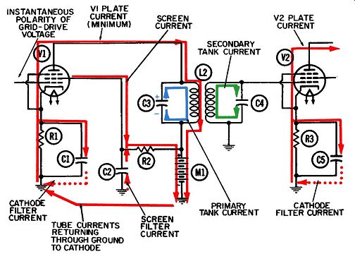
FIG. 5. Operation of the tuned-primary-tuned-secondary RF amplifier-first
half-cycle at resonance.
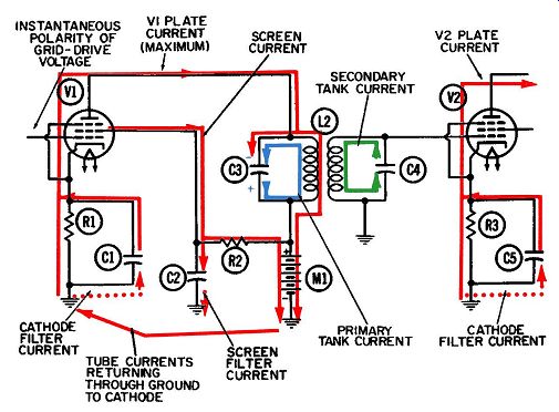
FIG. 6. Operation of the tuned-primary-tuned-secondary RF amplifier-second
half-cycle at resonance.
TUNED-PRIMARY-TUNED-SECONDARY COUPLING
Figs. 5 and 6 show two successive half-cycles in the operation of a radio-frequency voltage amplifier that has a tuned primary circuit on the plate (input) side and a tuned secondary circuit on the output side leading to the next grid. This is the second of the two most widely-used adaptations of transformer coupling at radio frequencies, the first being the untuned-primary-tuned-secondary one just considered.
A pentode tube again is used. It is not impossible to use specially-designed triodes at radio frequencies, but the pentode has several natural characteristics which make it much more suitable at radio frequencies.
One of these important characteristics is the shielding which the screen grid provides between the plate and control grid. As explained in Section 1, such shielding does much toward reducing or even eliminating interelectrode capacitance between plate and grid, and thus prevents feedback of energy from output to input. In Fig. 6-3 and 6-4 for the tuned-impedance-coupled amplifier, a feedback current was shown flowing from the tuned plate circuit back to the plate. Then by interelectrode capacitance it was coupled to the screen grid, from where it was bypassed to ground by the screen-grid filter capacitor.
Although this undesired feedback current is not shown in the radio-frequency circuits of this Section, it is always present, and it is a major consideration in the choice of a pentode tube.
Another important characteristic of the pentode is its shorter transit time. An electron will always require a finite amount of time, however small, to cross over to the plate after being emitted from the cathode. To the tube, this transit time becomes more and more of a limiting factor as the applied frequency rises and each cycle becomes correspondingly shorter. Here is a simple formula which relates the frequency to the duration of each cycle: where, 1 f=T f is the frequency of applied current in cycles per second, T is the duration of an individual cycle in seconds.
If a half-cycle of applied voltage is nearly equal in duration to the transit time, electrons will still be in transit within the tube (as a result of the positive grid voltage) after the advent of the next half-cycle has now made the grid voltage negative. The resultant phase shift between output and input usually limits or even destroys the utility of the tube.
A third and very important characteristic of the pentode tube is its high plate resistance. Recall from the first Section that the plate resistance is the ratio between a small change in plate voltage and the resultant small change in plate current when the grid voltage is maintained constant.
The several electron currents at work in this circuit include:
1. Grid driving current (not shown), the voltage polarity of which is negative on the first half-cycle and positive on the second.
2. Plate current through both pentodes (red).
3. Screen-grid current (also in red).
4. Cathode and screen-grid filter currents ( dotted red).
5. Plate tank current (blue).
6. Grid tank current for next stage (green). Both of the amplifier stages indicated in Figs. 5 and 6 are using cathode biasing. Since the existence of a cathode biasing voltage depends on the continuing flow of plate current through the tube, we have come to identify cathode biasing with Class-A operation of the tube---meaning that some plate current flows at all times throughout the entire cycle.
The details of grid driving, cathode biasing and filtering, screen grid filtering, etc., have been covered in many prior examples and will not be re-discussed here. The following discussion will be oriented around the phase relationships between the plate current, plate tank current, and grid tank current for the next stage. Once these currents and their phase relationships can be visualized for the condition of resonance and critical coupling, it becomes relatively simple to understand the small but important variations from this special case. These variations arise first from small changes in the signal or carrier frequency; as a result, the tuned circuits operate either above or below the natural frequency of the circuit. The second important variation arises from the degree of coupling.
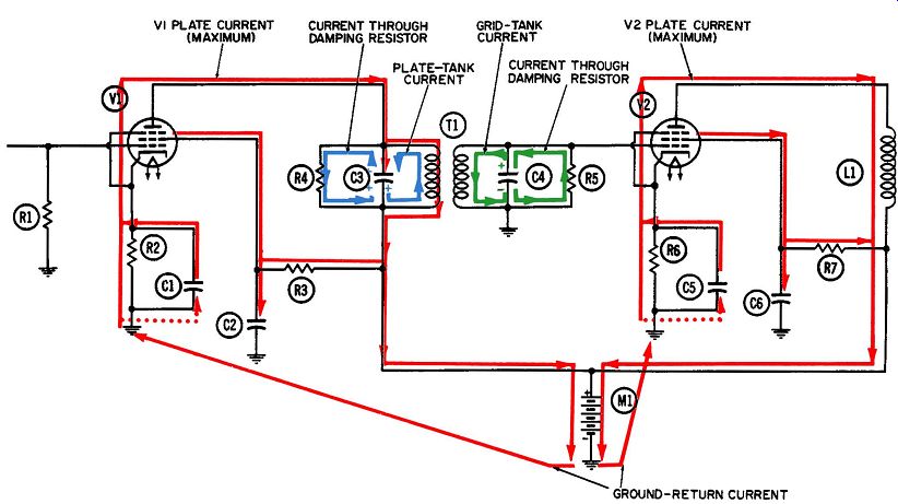
FIG. 7. Operation of the bandpass RF amplifier-first half-cycle.
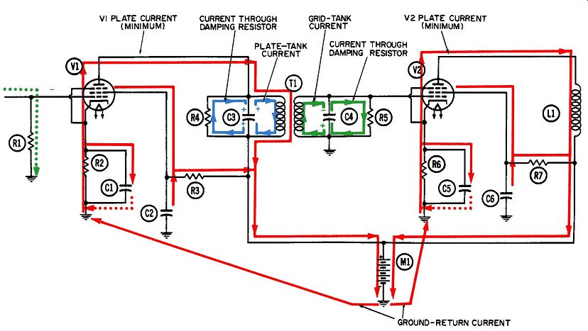
FIG. 8. Operation of the bandpass RF amplifier-second half-cycle.
The current diagrams of FIG. 3 can be adapted to the two tuned circuits (plate and grid tanks) of Figs. 5 and 6, but only where the latter circuits are being operated exactly at resonance. The five individual currents which should be identified separately would include:
1. Plate current.
2. Circulating current in plate tank. This is the primary inducing current, which function was performed by the primary plate current.
3. Secondary induced current.
4. Circulating current in grid tank.
5. Current re-induced in the primary by the circulating current in the grid tank.
The circulating current in the plate tank and the secondary induced currents are identical, as they were in the untuned example, and for the same reason. The circulating, or oscillating, current is in reality sustained or built up by this continual inducing of a current in the secondary winding.
The circulating current in the grid tank and the current re induced in the primary by this current are exactly out of phase with each other. As a result, the re-induced current opposes the primary tank current and thereby reduces the amount of current circulating there. This is similar to the untuned example discussed previously, where the current re-induced in the primary winding was opposite in phase to the applied plate current through this winding.
In this tuned example, the plate current supports or replenishes the oscillation of electrons in the plate tank, whereas the re induced current opposes this oscillation. Obviously, the plate current is strong enough to overcome this opposition and support the circulating currents in the two tuned tanks.
As in the untuned example, the reduction in primary tank current is due to the impedance coupled back from the secondary to the primary winding. When the opposing current is out of phase with the primary circulating current (as in this resonant example), the coupled impedance acts like a pure resistance inserted within the tuned circuit with a size that would reduce the primary current the same amount as it is in fact reduced by the out-of-phase induced current. If the flow directions of the tuned tank currents and induced currents are related to the polarities of the tank voltages and induced voltages, we will find that at resonance the two tank voltages will be 90° out of phase with each other.
THE BANDPASS AMPLIFIER
Figs. 7 and 8 show two half-cycles in the operation of a radio-frequency voltage amplifier being used as a bandpass amplifier. This type of circuit differs from the preceding example of a tuned-primary-tuned-secondary circuit only in the addition of the two resistors across the two tuned tank circuits. Their purpose is to reduce the response of the particular tank circuit at resonance. FIG. 9 shows a typical response curve for a highly selective, or high-Q, resonant circuit. It is obvious that the closer the current being amplified is to the resonant frequency of the tuned circuit, the larger the gain (response). Should we desire to amplify only a single frequency, the amplifier circuit could be tuned to that frequency and maximum amplification or gain would be realized. More frequently than not, however, we face the problem of amplifying not a single frequency, but a band of frequencies. The reason being that radio frequencies are usually carriers of intelligence superimposed at the transmitter by one of several processes of modulation. When ever a carrier signal is modulated by an audio signal, new radio frequencies-known as side frequencies or sidebands-are introduced.
As a simple example of what this means, assume we desire to amplitude-modulate a 1,000-kilocycle carrier signal with a 5,000-cycle audio signal. The radio-frequency signal would then consist of these three components:
1. The original carrier of 1,000 kc.
2. The carrier plus the modulating frequency, or 1,005 kc.
3. The carrier minus the modulating frequency, or 995 kc.
The 1,005-kilocycle signal is known as the upper sideband, and the 995-kilocycle signal is the lower sideband. To be acceptable, an amplifier must provide fairly equal amplification of all three.
It must "pass" a band of frequencies 10 kilocycles wide and centered at the 1,000-kilocycle point. An "ideal" response curve would look like a rectangle standing on end as shown by the dashed line in FIG. 9. Its response would be equal or flat over the 10-kilocycle band, and it would not respond whatsoever to any frequencies above or below this band. A more practical and realizable response curve is shown as a broader curve super imposed on the ideal curve. It is characterized by a rounded rather than a flat top, indicating reasonably uniform application over the passband. It also has sloping rather than vertical sides, indicating an acceptable (if not complete) attenuation of any frequencies above or below the passband.
Use of Damping Resistor
If a resistor is placed across a tuned tank, the tank voltage will be prevented from building up as high as it would otherwise.
The resistor acts as a "load" on the oscillation of electrons-any unbalance in voltage across the tank capacitor will begin redistributing itself through the resistor. From FIG. 7, we see electron current flowing from the upper plate of tank capacitor C3, to the lower plate, through resistor R4. This direction of flow will persist as long as the positive voltage on the lower plate of C3 is higher than the positive voltage on the upper plate. Also, in FIG. 7 we see electron current flowing out of the bottom plate of grid tank capacitor C4 and upward through resistor R5 to the top plate. This flow will persist as long as the voltage is more negative on the lower than on the upper plate.
In both tanks in FIG. 7, the tank currents flow onto the respective plate of each capacitor, trying to build up a high peak voltage; at the same time, electrons are being drained off through the resistors. It is this continual drainage that prevents the achievement of high peak voltages and sharp response curves at resonance. A resistor of high ohmic value drains off only a small amount of current and so constitutes a "light" load on the tank circuit. Conversely, a low-value resistor will drain off much current and constitute a "heavy" load.
In FIG. 8, the polarities of the two tank voltages have been reversed, and so have the directions of electron flow through the two bandpass resistors. The tank-voltage polarities, tank-current directions, and flow directions of the resistor currents will be discussed later for each quarter-cycle.
Critical Coupling
Two tuned circuits are said to be "critically" coupled whenever they give a single response peak at their resonant frequency.
Either one of the response curves in FIG. 9 could result from critically coupled tuned circuits. However, a damping resistor such as R4 or R5 (Figs. 7-7 and 7-8) is not normally used with critical coupling. When it is desired to pass a band of frequencies, the tuned circuits would be "over-coupled." FIG. 10 shows three response curves for three degrees of overcoupling. Contributing to the width of these double-humped response curves are the size of the resistors across the tuned circuits, their Q (quality), and finally the degree of overcoupling between them. Overcoupling is the opposite of "loose" coupling.
The value of critical coupling can be determined by the formula: 1 where, K is the value of critical coupling, Q1 is the Q of the plate tank circuit, Q2 is the Q of the grid-tank circuit.
As an example, if each tuned circuit has a Q of 100 (which is not unreasonable), the value of critical coupling, K, would be .01 and a single-peaked response curve similar to those in FIG. 9 could be achieved.
Overcoupling
If the two inductor windings are wound closer together, or if the coupling between them is increased by adjustment of a variable core, the coefficient of coupling will be greater than .01 and the circuits will be over-coupled--the objective in the design of bandpass amplifiers. The double humps in the response curves of FIG. 10 are the result of resonances occurring at frequencies on either side of the natural frequency. FIG. 11 has been drawn to represent four successive quarter-cycles in the operation of the two tank circuits of FIG. 7, when these circuits are being operated above the resonant frequency.
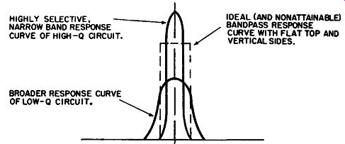
FIG. 9. Response curves of high- and low-Q circuits at resonance.
It was previously stated that when two tuned circuits are coupled together at their resonant frequency, the two resulting tank voltages are 90°, or a quarter of a cycle, out of phase with each other. However, as soon as the frequency being amplified deviates even slightly from the resonant frequency of the tanks, the phase difference will increase to a maximum of 180°, or half a cycle. With very high-Q circuits, this 180° phase difference between the two tank voltages will occur fairly close to the resonant frequency. The inside curve of FIG. 10, with its two resonant peaks fairly close together, represents the response of a high-Q circuit and the outer curve, with its resonant peaks far apart, the response of a lower-Q circuit.
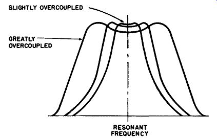
FIG. 10. Response curves of over-coupled tuned circuits.
Thus we see that either the Q of the tank circuits, or their degree of overcoupling, can have an effect on where these resonant peaks occur and consequently on the width of the passband.
Operating Above Resonance
Let us assume in FIG. 11 that the current being amplified is higher than the resonant frequency of the tank circuits. Then each tank circuit will appear to be inductive to these currents. The reason is that the inductor and capacitor are in series with each other (as far as the circulating current is concerned), and when ever the frequency rises, the inductive reactance increases and the capacitive reactance decreases. Either tank circuit will appear to be completely inductive to its circulating current as soon as the internal resistance of the tank becomes negligible (compared with the inductive reactance). Since capacitors and connecting wires have minute amounts of resistance, most of the internal resistance of a tank is due to the resistance of the wire composing the coil.
In a high-Q coil this resistance is of course very small, as illustrated by the formula for the Q of a coil: where, Q=wL R w equals 2,,. times the frequency of operation (called omega), L is the inductance of the coil in henrys, R is the resistance of the coil in ohms.
The quantity, wL, is also the inductive reactance of the coil at the frequency of operation.
Phase Relationships
In the previous example of two tuned circuits operated at resonance, the primary tank current induced a secondary tank current. Along with this secondary tank current was an induced secondary voltage, and the two were in phase with each other, since the inductive and capacitive reactances had equal but opposite values and canceled each other. So the series impedance of the secondary tank circuit was purely resistive.
In the example we are considering here, when the secondary tank circuit is operated at some frequency higher than resonance, the capacitive reactance is opposite but not equal to the inductive reactance. Only part of the latter is canceled, and the circuit is inductive rather than purely resistive. Therefore, the primary tank current still induces a secondary tank voltage which lags the primary tank current by 90°. However, instead of being in phase with the induced secondary voltage, the secondary induced current lags it by another 90°, because in an inductive circuit the current always lags the voltage by 90°. During the first quarter-cycle, in FIG. 11A, the primary tank current is flowing--upward through its inductor at its maximum rate. However, the induced secondary current is flowing down ward through its inductor at its maximum rate. This denotes that the two are 180°, or half a cycle, out of phase. Both currents, the inducing and the induced, are shown in blue so they can be more easily related to each other.
The secondary tank current, shown in green, is an oscillation of electrons supported by the secondary induced current (in fact, these two currents are normally indistinguishable). Like all electron oscillations in tuned L-C circuits, energy is stored alternately in magnetic and in electric fields. The magnetic field is maximum when the tank current reaches maximum, at the end of the first and third quarter-cycles. The electric field is maximum when the voltage across the tank capacitor is maximum, at the end of the second and fourth quarter-cycles.
The secondary tank current also re-induces a new voltage in the primary circuit, which lags the secondary current by 90°. The primary circuit is inductive for the same reason the secondary is.
When the operating frequency is higher than the natural frequency of the circuit, all capacitive reactance is canceled but some inductive reactance is left over. When this inductive reactance becomes significantly larger than the winding resistance the primary tank circuit will appear as a pure inductance to the induced primary current. This current will thus lag the induced primary voltage by another 90°, and consequently be 180° (or half a cycle) behind the phase of the original tank current in the primary circuit.
Two events which are a whole cycle out of phase with each other are actually "in phase," so that the primary induced current adds to and thus strengthens the primary tank current. Thus, the response curve is peaked at a frequency higher than the resonant frequency and the primary tank appears to be operating at resonance, when we know this cannot be true.
In each of the four quarter-cycles shown in FIG. 11 we see an induced primary current flowing in phase with the primary tank current. There is also an induced secondary current flowing in phase with the secondary tank current.
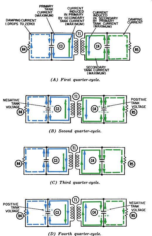
FIG. 11. The four quarter-cycles of operation of the bandpass tank circuit
at a frequency above resonance.
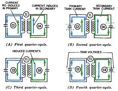
FIG. 12. The four quarter-cycles of operation of the bandpass tank circuit
at a frequency below resonance.
Operating Below Resonance
The diagrams of FIG. 11 cannot be applied equally well to two tuned circuits operating below their resonant frequency.
When this happens, each of the inductive reactances of the two windings will decrease and the capacitive reactances of the two tank capacitors will increase, in accordance with the standard reactance formulas. To a current circulating within either tank circuit, the over-all impedance of its series path will be capacitive, since all inductive reactance in each path will be canceled but some capacitive reactance will be left over. Now it becomes interesting to analyze the phase relationships between the two tank currents and their voltages, and between the two induced voltages and their currents.
In FIG. 12A, the primary tank current is flowing upward through the primary winding and again induces a voltage in the secondary winding which lags the primary current by 90°. There fore, the secondary voltage is zero at the end of the first quarter cycle. This induced voltage will have an induced current flowing with it; but since this current is flowing in a circuit that is capacitive, it will lead the voltage. This means maximum current occurs 90°, or a quarter of cycle, in advance of the maximum voltage or exactly in phase with the inducing current. In the four quarter-cycles of FIG. 12 we see the induced secondary current, shown in blue, flowing in phase with the inducing primary cur rent, also shown in blue. As in the previous example, the induced secondary current supports the oscillation of electrons in the second tank and these two currents are indistinguishable. Both the primary and the secondary tank currents cause tank-voltage peaks at the end of the second and fourth quarter-cycles. Unlike the previous example, these tank voltages are in phase with each other-that is, their positive and negative peaks each occur simultaneously.
The secondary current also induces a voltage in the primary which lags the secondary current by a quarter of a cycle. The induced primary current associated with this induced voltage leads the voltage by a quarter of a cycle, because of the capacitive reactance exhibited by the primary circuit when operated below resonance. Thus, the induced primary current turns out to be exactly in phase with the original inducing current, or primary tank current.
Consequently, when operated below resonance, both induced currents will reinforce their respective oscillating tank currents, causing them to build up in a manner similar to a current build up at resonance.
The damping resistors of FIG. 11 have been omitted from FIG. 12 for clarity. However, they would be required in the normal bandpass amplifier, whether it is being operated above or below resonance. During the first and third quarter-cycles, electrons flow through these resistors in unison with the electrons which flow through the respective inductors. During the entire first quarter-cycle, some excess electrons are amassed on the lower plate of capacitor C3, and they flow from this plate upward through the inductor and resistor. During the entire third quarter cycle, some electrons are amassed on the upper plate of capacitor C3, and they flow from this plate downward through the resistor and inductor.
During the second and fourth quarter-cycles, the currents through the resistor and inductor do not appear to be flowing in unison with each other. During the second quarter-cycle, while the oscillating tank current is delivering electrons to the upper plate of C3 and trying to build up a tank-voltage peak, the resistor is letting electrons drain off. During the fourth quarter cycle, a similar situation is occurring at the bottom plate of C3.
Resistor R5, bridged across the secondary tank circuit, acts in a similar manner to prevent the attainment of a high peak voltage across the secondary tank.
SERIES VERSUS PARALLEL IMPEDANCE
One of the hallmarks of a parallel-resonant tank circuit is the high impedance it presents to an external circuit. At the same time, the tank circuit presents an extremely low impedance to a current circulating within it. The reason is that the inductive and capacitive components are in series resonance to the circulating or oscillating current, so their respective reactances cancel each other.
When we say that a parallel-resonant tank circuit offers high impedance to an external circuit, we are referring to its opposition to the passage of an external current. A tuned tank in the plate circuit of an amplifier tube, as discussed earlier, offers a good example from which to explain the meaning of the term, high parallel impedance. Whenever any of these tuned plate tanks is operated at resonance, the ratio between tank voltage and line current (plate current) will reach its highest value. This ratio, called the tank impedance, is derived from the fundamental Ohm's-law relationship which states that the voltage across a resistor (or network) is proportional to the current through it.
In a pentode tube, as we tune a tank towards resonance the tank voltage rises, meaning a large number of electrons are in oscillation, whereas the plate current is virtually unchanged.
This gives a high ratio of tank voltage to line current, and consequently a high-resonant impedance. When the circuit is operating off-resonance, the amount of circulating or oscillating current is greatly decreased. This leads to a lowered tank voltage and tank impedance.
In a triode amplifier using a tuned plate tank, the amount of plate current will be greatly reduced when the tank is at resonance, because the negative (or low-positive) voltage peak at the plate occurs simultaneously with the positive grid-voltage peak.
The latter is trying to release maximum current through the tube, whereas the low plate voltage restricts the plate current.
A simple operating test for resonance is to tune the tank slowly near the resonant frequency and observe the amount of plate or line current with an ammeter. The point where minimum plate current is achieved indicates the tank is resonant and its tank voltage is maximum. Obviously, the ratio between maximum tank voltage and minimum line current indicates the highest attain able value of tank impedance, or resonant impedance.