
By JIM LONG [Electro-Voice, Buchanan, Mich. 49107, USA]
Choosing Between Omnidirectional and Cardioid: A Summary
THE DISCUSSION of cardioid designs in Part 1 made clear the advantages and compromises involved, to the point that a choice will be obvious in many instances. The following is a summary, with amplifying commentary.
Partly because of the compromises involved in cardioid microphone design as well as the advantages inherent in omni-directionals, it is prudent to reject the panacea that states "cardioids are the all-around best." This frequently-seen statement is apparently based on the assumption that feedback, background noise, and room reverberation are lurking in the wings, ready to sabotage any effort involving microphones! Although the panacea should be rejected, a knowledge of microphone performance characteristics permits several reasonably clear statements.
If You Have a Choice, Try an Omni First.
Many recording and sound reinforcement activities could well benefit from an omnidirectional microphone. Try one where you would never dare. You'll be surprised! If you can afford only ONE type of microphone in sound reinforcement, buy a cardioid. This is because feedback is frequently the overriding concern in sound reinforcement.
Keep in mind, however, that where microphones are handheld at close working distances the feedback-reducing nature of a cardioid is often not needed-and neither are its higher susceptibility to breath popping and mechanically-induced noise! Also, a cardioid with rough frequency response may feedback more easily than a smooth omnidirectional.
If you can afford only ONE type of microphone for recording, buy an omnidirectional. The advice runs contrary to many recording recommendations, but comes from experience in recording the usual run of things encountered by the serious amateur recordist: choirs, bands, vocal and instrumental ensembles, pipe organs, etc. The rationale follows! First, at a given price level, omni-directionals nearly always have the smoothest and most extended frequency response.
This situation may contribute to the observations of "open" and "airy" that some enthusiasts attribute to a microphone's omni-directionality alone.
Second, the need, in recording, for a cardioid's reduction of room reverberation and unwanted background noise is often overrated by amateurs and professionals alike. Background noise is typically not unduly annoying and can often be controlled if it is (pull the switch on the air-handling system). As for reverberation, it is frequently a fight to get enough of the room "sound" that is so much a part of an effective listening experience, live or recorded. To sum up, two properly placed omnidirectional microphones can provide impressive musical results with a minimum of risk and frustration! Naturally, if a selection of microphones is possible, cardioids would be among them, first to control reverberation and noise when it is uncontrollably excessive, and, second, to utilize the off-axis rejection to solve problems of balance in "classical" two-mic stereo recordings and problems of instrumental isolation in multiple-microphone recording.
This is business for the more advanced recordist; important tips are discussed later.
Cardioids are also appropriate where recording is nonmusical. The acoustics of a living room are not an essential part of a good recording of a child's voice, for instance.
It would be more useful to suppress the sounds of gurgling radiators, tape recorders, or vociferous guests, by aiming the "dead" side of a cardioid at the offending noise sources!
What Frequency Response Is for You (And How to Get It)?
"Flat and very wide," would be the first answer. But wait a minute! "Peaky" and rough, of course not, but it turns out that smooth nominal deviations from ruler-flat response can be useful.
These deviations would certainly not, it seems, be unalterably built into the electronics and loudspeakers used in home and studio environments. Speakers and amplifiers should be flat, or should be able to be made flat, for reference. But microphones are small and easily changed, one for another, promoting a healthy atmosphere of "getting the sound you want." In the professional studio, different microphone responses are easily modified by sophisticated equalization facilities, but these facilities are not as yet widely available to audiophiles. So it pays to know the several basic response options available from many microphone manufacturers.
Bass Response in Omnidirectionals
It is generally easier to get flat, extended bass response in an omnidirectional design. Many omnidirectional dynamics are essentially flat to 40 or 50 Hz, with fairly rapid rolloff below. Many omnidirectional condensers-even one or two of the modestly-priced electrets-are essentially flat to 20 or 30 Hz. Actually, it is virtually impossible not to have super extended bass in an omnidirectional condenser, as long as the internal impedance converter has sufficiently high input impedance.
Even 40 or 50 Hz response surpasses the flat-response portion of many, many loudspeakers, and can be downright impressive on pipe organ material. However, if pipe organ and bass drums are your specialty, and you've seen to it that the rest of your system can reproduce them, microphones flat to 20 or 30 Hz can he lots of fun! They also pickup subways very well.
Bass response in Cardioids
It is much more difficult to attain flat, extended bass response in both dynamic and condenser cardioid designs, though conventional condensers usually exhibit less rolloff than their dynamic counterparts. The rolloff in both designs is not sharp, but gradual, typically flat at 200 Hz, l-to-5 dB down at 100 Hz, and 5-to-15 dB down at 50 Hz. Single-D dynamic designs usually follow the lower limit, in part to compensate for proximity effect's close-up bass boost and to minimize sensitivity to mechanical shock.
Cardioids absolutely flat in the 50-Hz-and-below range to exist, but are rather rare, and often have other performance defects.
The Case for Tailored Response
There are three reasons why the rolled-off, "tailored" low-frequency response typical of many cardioids can be very useful under adverse conditions. The usefulness is universal enough to have made available a number of similarly-tailored omnidirectional microphones.
1. Much of the "bass" we hear does not range below 100 Hz.
Even if the fundamental is substantially below 100 Hz, the ear often reacts more strongly to the harmonics and doesn't feel cheated if the fundamental is reduced a bit in amplitude. A piano is a good example.
The second and third reasons need an introduction: Our ears and brain can discriminate between wanted and unwanted sound in a way far superior to anything that can be built into a microphone polar pattern or a two-speaker stereo setup. We hear, to a great extent, what we want to hear. The only way we usually hear a refrigerator compressor is when it shuts off! Microphones, however, even in stereo and with cardioid patterns, pick up the noise and send it through the loudspeakers as clearly heard as the music.
2. Much of the unwanted noise encountered under adverse conditions is very low frequency. It may therefore be subjectively more pleasing to loose a little bass fundamental in order to eliminate the noise.
3. Reverberant sound is bass oriented. Sometimes microphones must be located relatively far from the performers, in their reverberant field. This would tend to occur with cardioids placed to take advantage of their working-distance expansion. In this case, a high percentage of the sound reaching the microphone is reverberant. To the extent that reverberant sound favors the low frequencies, as it often does, the pickup will be over-bassed with a flat microphone.
A subjectively flatter sound would result if the bass were rolled-off. This phenomenon also justifies a moderate, broad rise in high-frequency response. This alternative is available in some microphones.
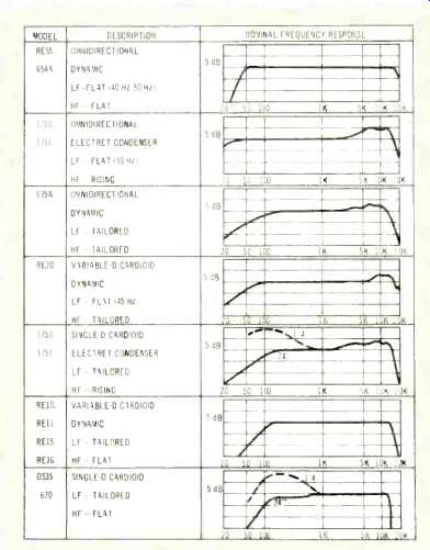
Microphone Response Table
To take the above discussion out of the range of an academic curiosity, Table I lists a number of Electro-Voice microphones that give the various response alternatives mentioned above. Happy experimenting!
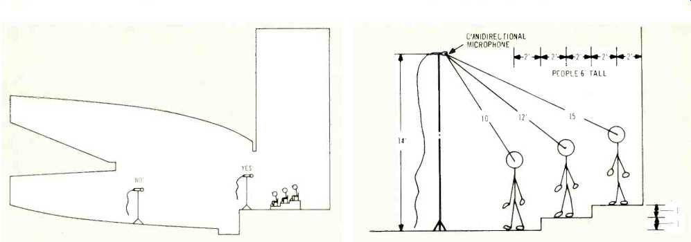
above: Guidelines for Placement in Recording
"Classical" Two-Mic Stereo
The easiest way to get a stunning recording with a minimum of rush and frustration is to record with two microphones located relatively high, separated by a number of feet, in front of the performing ensemble. If there ever was a panacea for the serious amateur in the recording field, "two microphones in front of the group" is it. Two tips and some sketches will be helpful.
The "best seat in the house" is not the best place for microphones! In general, the recorded pickup from "the best seat in the house"-with either omnidirectional or cardioid microphones-will sound distant, lacking the impact, presence, and sizzle of a live performance. Though going from monaural to stereo substantially reduces this problem, the by-now familiar inability of recording techniques to duplicate the discriminatory powers of our ears and brain is once again the culprit.
The solution is simple: move the microphones closer to recapture the clarity. Right up on stage with the ensemble will do. Figure 18 illustrates a "reasonable" microphone setup. The idea is to get good perspective, a decent compromise between a bright, clear sound and a nice feel of the room acoustics, and 2, preserve the balance heard in the hall-with no row or section of the ensemble overpowering another due to poor microphone placement.
In general, the perspective will be bright and clear, with little hall sound, for relatively close miking distances. It will be dull and muffled, with lots of hall sound, for relatively large miking distances. The perspective inherent in a particular microphone and hall situation can only be determined accurately by making trial takes at several microphone working distances and monitoring the results on loudspeakers (headphones are better than nothing but create a "larger-than-life" sound, compared to the same tape reproduced on spaced loudspeakers). Fortunately, in practice, a fairly broad range of perspectives produces a very acceptable recording (though what is "ideal" is an elusive and very personal judgment). Therefore, the recordist who is not blessed with the luxury of experimentation time will probably be in good shape if his microphones are 10 to 20 feet from the middle of the source, for the typical chorus, band, orchestra, or organ. Very small ensembles could use closer miking-say 5 to 10 feet-but the room sound would be reduced.
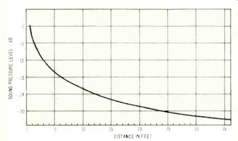
The recordist must, however, be concerned about balance, which he can do without rehearsal. In considering balance, it helps to remember the inverse square law. The direct sound from a section of the performing group will experience a 6 dB loss in level every time the distance from that section is doubled. If microphones are relatively close to the group as a whole, the rear row can easily be twice the distance from the microphones as the front row. This spells balance problems. Such a large relative difference does not occur if microphones are placed at a greater distance from the group as a whole. Figure 18A illustrates the inverse square law.
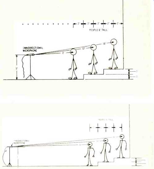
In general, the recordist will find that, given an adequate setup with respect to direct-to-reverberant perspective, his distances for proper balance will put the microphones fairly high, as in Fig. 19. Figure 19 places the microphones at approximately 12 feet from the middle of the group and the extreme distances (10 feet and 15 feet) are consistent with good balance. Figure 19A preserves the same 12-from-the-middle distance, so perspective is unchanged. Balance, however, definitely favors the front row (8 feet from the microphones) and the rear row will be weak and indistinct (16 feet). Figure I9B, with the short microphone stands move to 24 feet from the middle of the group, restores balance but the pickup includes too much of the room sound muddy and lacking in presence. Moral: the usual five-foot microphone stands are often not particularly useful to the serious amateur recordist!
If the 24 foot distance shown in Fig. 19B must be used, cardioid microphones will help restore proper perspective.
Figure 20 is a view from the top, to illustrate distance between the two microphones in a stereo pair. A reasonable guide is to center each microphone on one-half of the group.
Again, this distance is fairly non-critical, but extremes will upset balance and significantly alter the stereo effect.
Microphones too far apart from left to right will produce a hole-in-the-middle, a disjointed, schizophrenic effect, lacking in solidarity. Microphones too close together tend toward monophonic reproduction, destroying stereo's sense of direction and hall acoustics.
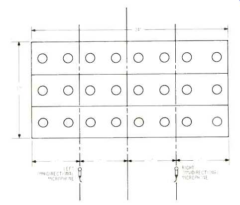
Fig. 20--Typical left-to-right separation.
What About Soloists?There seems to be an innate urge--perhaps because of the wide availability of microphone mixers-to augment the classical two-mic setup by "spotlighting" the soloists with an accent microphone. After all, we don't want to loose anything! In years past, the grave compromises of monophonic reproduction forced the spotlighting of soloists: the subjective realism of monophonic reproduction was improved. Stereo is certainly not a complete answer, as mentioned earlier, to sorting out wanted and unwanted information (witness the great amount of accent miking done in professional recording sessions). It is, however, a sufficient improvement to make the added responsibility and complexity of accent mics usually not worth the amateur's effort. The key word is "responsibility;" the amateur is mixing in real time, without the benefit of multichannel recording, and if he accents too much (which seems to be a universal tendency) it's just too bad. Let things fall where they may, with just a stereo pair of microphones; you will he pleasantly surprised.
It is perhaps worth noting that four-mic/four-channel recording reduces the need for accent microphones even further. The ability of four-channel stereo to sort out a single event amidst complex aural confusion-if the recording is properly handled-can be downright uncanny! Tips on Taking
Advantage of Cardioids
The recording advantages of cardioids, with their reduced pickup to the sides and rear, have been mentioned earlier: (l) control of reverberation and background noise and (2)
solving problems of instrumental balance and isolation when miking under what might be termed adverse conditions. To put the second item another way, a cardioid will let you "patch things up" when a straightforward two-mic stereo setup, as just described, cannot provide optimum balance.
In performing such a patch-up, however, it should be remembered that a cardioid accepts sound equally well over a surprisingly wide angle. Reference to Fig. 8 shows that output is constant over nearly an 80-degree angle. If a too-loud instrument or group is to be reduced in level to any extent at all, a cardioid microphone would have to be oriented at least 45° off axis, 90° off axis would provide just a 6 dB reduction.
Cardioid Polar-Pattern Uniformity
Some cardioid microphones (especially inexpensive ones) are cardioid only over a certain range of frequencies. In practice, it is no simple task to maintain the ideal cardioid pattern throughout the frequency range. Off-axis pickup, then, will be colored to the extent that the polar pattern is not uniform with frequency. As long as the microphone is pointed at the group of interest, the audible effect is not too severe, but if a major portion of the ensemble is being picked up off axis, any coloration is unfortunate.
Avoiding Acoustic Phase Interference When Multiple Miking
It is certainly no secret that "classical" two-mic stereo recording plays a very small part in commercial recording today, especially in the predominant recording of contemporary rock and jazz. Instead, multiple microphones are used, virtually one for each instrument or small section. Each microphone is fed to a separate track on a multi-channel recorder--up to 24 channels, at last count. The microphones are placed very close to the instruments--from "right in the bell of a trumpet" to a foot or two away. The pickup is bright and very dry, with no natural room sound. Tracks are often recorded at separate times, redone if necessary, and then mixed down to form a two-channel working master which eventually appears as the stereo disc. Equalization and artificial reverberation are added at many stages in the process.
The ready availability of microphone mixers often tempts the amateur recordist to make his own multiple-microphone recordings. It's lots of fun, but certainly not the "easy" way. Without multi-channel recorders, the session must be mixed live, in real time, with no opportunity for remix or re-recording of offending tracks. Again, responsibility rears its head: the balance and perspective are entirely in the hands of the recordist. The musicians' natural balance has nothing to do with it!
Acoustic Phase Interference
Even more serious than the responsibilities of balance, however, is the problem of acoustic phase interference. This phenomenon causes huge, varying voids in frequency response that create, at best, a vague feeling that "something's terribly wrong." Figure 21 shows the basic elements: a vocalist being picked up by two microphones whose outputs are being combined in a microphone mixer. The second microphone (to the right) is of course intended to pick up another vocalist (or instrument), but in fact does a pretty good job of picking up the first vocalist!
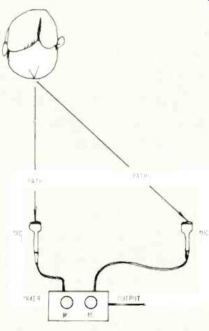
Fig. 21-Basic mechanism of acoustic phase interference.
The interference arises because the sound of the first vocalist reaches the two microphones at slightly different times, since path 2 is longer than path 1. Depending on the frequency and distances involved, the two signals, when combined in the mixer, either add (in phase) or cancel (out-of-phase), or something in between. The effect is audibly shocking and is shown on a frequency response basis, for several distances between microphones, in Fig. 22. The first curve shows the response of the left microphone alone. The remaining curves show the combined response as distance between microphones is increased. Complete interference is eliminated only at a rather large distance, but 3 feet is relatively void free and suggests the following rule-of-thumb.
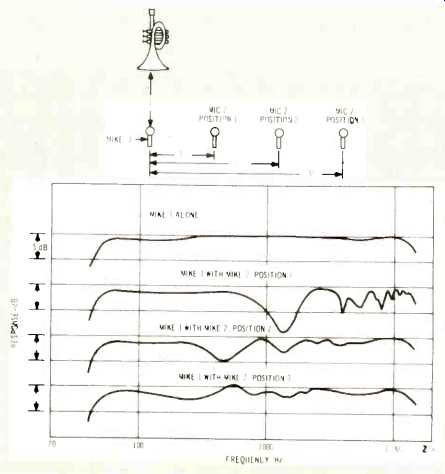
Fig. 22--Acoustic phase interference as a function of distance between microphones.
The Three-to-One Ratio
To avoid acoustic phase interference, the distance between microphones should be at least three times the distance between the sound source and the nearest microphone. Several good and bad multiple-mic setups are shown in Fig. 23.
Strictly speaking, the three-to-one rule assumes sound sources of equal level. If meters are available on the mixer or recorder, however, even unequal levels can be handled.
A little slide-rule work will show that the three-to-one ratio implies an isolation of 9 dB. If the gain on the right mic is such that its pickup of the left instrument is 9 dB below the pickup of the left microphone, interference will be acceptably low. It is interesting to note that many professional recording people do not observe this rule, and that if they did, the need for so-called "flats" or "baffles," with their imperfect solution to isolation or separation problems, would not exist!
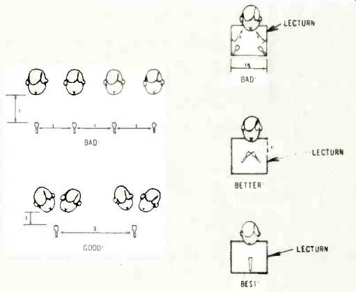
Fig. 23--"Good" and "bad" multiple miking setups.
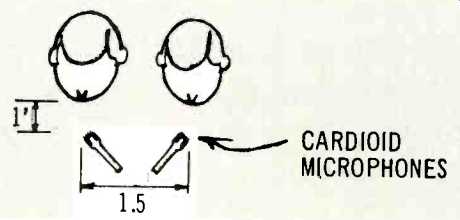
Fig. 24--Decreasing the 3-to-1 ratio with cardioid microphones.
Beating the Three-to-One Ratio with Cardioids
A cardioid's rejection of sound from the sides and rear, if properly applied, can reduce the three-to-one ratio. Figure 24 shows two cardioids angled away from each other, to increase isolation and decrease interference.
Connecting the Microphone to the Preamplifier Input
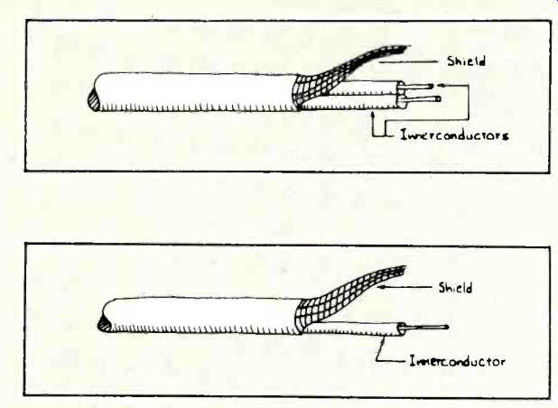
Fig. 25--Single-conductor shielded cable.
Fig. 26--Two-conductor shielded cable.
High-impedance cable and inputs: High impedance cables are single-conductor shielded, as shown in Fig. 25. The output of the microphone is carried by the inner conductor and shield, which also acts as ground to prevent hum. High impedance preamplifier inputs have two connections, with the shield going to the preamplifier's ground. Because one of the microphone's output terminals is connected to ground in such an input, the inputs are called unbalanced Low-impedance cable and inputs: Low impedance microphone cables have two inner conductors and a shield, as shown in Fig. 26. In such low impedance cables, the micro phone output is carried on the two inner conductors, while the shield acts only as a hum and noise protector. This configuration is termed balanced line since neither microphone output terminal is connected to ground. The balanced line arrangement provides hum and noise protection superior to the unbalanced lines used with high-impedance microphones.
Low impedance microphone preamplifier inputs generally have three connections, with the shield going to ground.
Occasionally, preamplifier inputs for low-impedance microphones will have two connections like typical high-impedance inputs. Such low-impedance inputs are unbalanced, similar to their high-impedance counterparts. In order to use an unbalanced input with a standard low impedance microphone cable, one inner conductor must be connected to ground. This should be done at the preamplifier input only, by connecting either one of the inner conductors to the shield at the preamplifier input.
The Truth about "Impedance Matching"
Microphones are connected to preamplifier inputs whose impedance "looking in" varies widely. There is often great concern to "match" the microphone impedance to that of the input. A microphone should certainly be suited to its input, in terms of voltage delivered and the input's compatibility with that voltage, but this certainly does not necessarily mean equating ("matching") the microphone and input impedances! If matching were necessary, life would be indeed difficult, since examples of the following are everywhere to be found:
1. A fine line of tape recorders whose inputs are recommended for use with "low-impedance" microphones but whose input impedance is 600 ohms.
2. A popular microphone mixer whose balanced "low-impedance" microphone inputs are actually about 800 ohms.
3. A high-quality home recorder whose unbalanced microphone input works with many low-impedance microphones, yet the measured impedance of the input is 10,000 ohms.
4. A fine microphone rated at 150 ohms whose measured impedance is nearly 400 ohms.
What gives? It turns out, since they are essentially resistive sources, that ribbon, dynamic, and condenser microphones may be loaded with any impedance value from slightly below their rated impedance on up to an open circuit. Distortion and frequency response are not affected.
Only output voltage level is affected: maximum output is achieved into an open circuit with output reducing as the load impedance is reduced. The loss is 6 dB when the load impedance equals the microphone's measured impedance.
"Line matching" transformers may now seem mis-named: they are perhaps more clearly viewed as voltage step-up devices, increasing the low output level of low-impedance microphones to a higher level more appropriate to the sensitivities of typical high-impedance microphone inputs.
Capacitive-source piezoelectric microphones (ceramic or crystal) are affected quite differently by cables and preamplifier input impedances. Such microphones are referred to as high impedance, but this is purely capacitive and of quite a different nature than the resistive high impedance of, say, a dynamic microphone. The impedance magnitude is a function of frequency. For capacitive-source mics, added capacitance of longer and longer cables has no effect on frequency response, since both the source and cable impedance change proportionately, with a constant voltage-division effect maintained. Level, however, drops drastically.
Output Level or Sensitivity
Microphone output level or sensitivity is a way of expressing the microphone's "output" when 1, loaded in a specific manner (RL) and 2, driven with sound of a specific "loudness." Output level is usually given at a single frequency.
Two commonly used frequencies are 1000 Hz and 250 Hz.
The 1000-Hz measurement is used for speech-frequency, communication-type microphones, and the 250-Hz measurement is used for the wide-range microphones more likely to be employed by the serious amateur and professional.
Sensitivity often is expressed as "-60 dB." This figure is absolutely meaningless. It could refer to several valid, though different, rating methods now currently used by the American audio industry. If the actual voltage delivered to the amplifier input is desired, some or all, depending upon which rating method is employed, of the following additional information is required to give the "-60 dB" meaning: 1, the sound pressure level driving the microphone, 2, the internal impedance of the microphone (RG), and 3, the load on the microphone (Rt.). The two most used sensitivity specifications are discussed below.
Open-Circuit Voltage Rating
This rating is most frequently applied to high-impedance microphones, but may be applied to microphones having any source-impedance value. The open-circuit method states explicitly the load (RL) as open circuit. In practice, measurements may be made as long as RL is about 20 times that of RG. The error would be limited to about 0.1 dB. A microphone rated according to the open-circuit method would read, stated completely: Sensitivity = -60 dB re/1 volt/microbar.
The "re" (referred to) is the key to our question of what voltage drives the amplifier, and is part of the sensitivity statement because the rating is expressed in dB. Decibels, like per cent, are a relative measurement. If we want an absolute answer from the dB sensitivity rating, we must answer the question "relative to what?" As an example, we could say that board "A" is three times the length of board "B." That's relative. If we want to know exactly how long board "B" is, however, we must know the length of "A." If "A" is three feet, then "B" is, absolutely, 9 feet. Returning to the open-circuit microphone voltage rating, the only difference is that the reference is "1 volt," rather than "3 feet."
(Audio magazine, Jan. 1973)
Also see:
A Microphone Primer: Basic Construction, Performance, and Applications (Dec. 1972)
A Microphone Primer: Conclusion (Feb. 1973)
Mike Technique and Sound Effects (Dec. 1974)
Electro-Voice microphones (Jan. 1973)
Microphones--The Vital Link in the Recording Chain (Dec. 1973)
= = = =