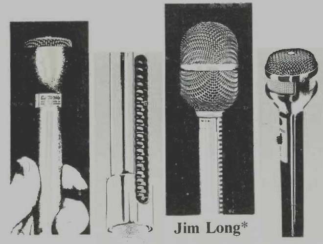
by Jim Long [Electro-Voice, Inc., Buchanan, Mich. 49107.]
A MICROPHONE is a transducer--it changes one form of energy into another. Specifically, a microphone converts the air pressure variations of sound into corresponding changes in output voltage.
The ways of accomplishing this task are many, each full of pitfalls for the would-be successful microphone user. This review refuses to yield to the "we have analyzed the situation and selected the best microphone for you" temptation. Instead, it outlines (in Part I) the key differences in microphone construction and performance characteristics, followed (in Part II) by a practical applications guide [in a future issue -Ed.]. The goal is to provide basic information from which an intelligent and relatively painless microphone selection may be made. The review applies to both sound reinforcement and recording, but greatest emphasis is placed on the recording of musical events by the serious amateur.
Part I: Basic Construction and Performance
A microphone is often listed in a catalog as "Dynamic Cardioid, Hi-Z" or "Condenser Omnidirectional, Low-Z." Each description, though by no means offering anything near complete definition of the microphone, includes three of the most important factors needed to define a microphone: 1, type of generating element, 2, type of pickup pattern, and 3, microphone impedance. Part I is devoted to these three primary factors. The new microphone enthusiast will be surprised by the many byways discovered along the way!
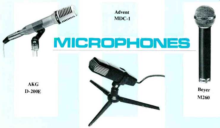
Generating the Output Voltage
A microphone's output voltage is produced by two basic components acting together. The diaphragm is a membrane which vibrates in accordance with the air pressure variations of sound. A generating element converts the diaphragm vibrations into output voltage. Generating elements vary greatly in expense, fidelity, complexity, ruggedness, and longevity.
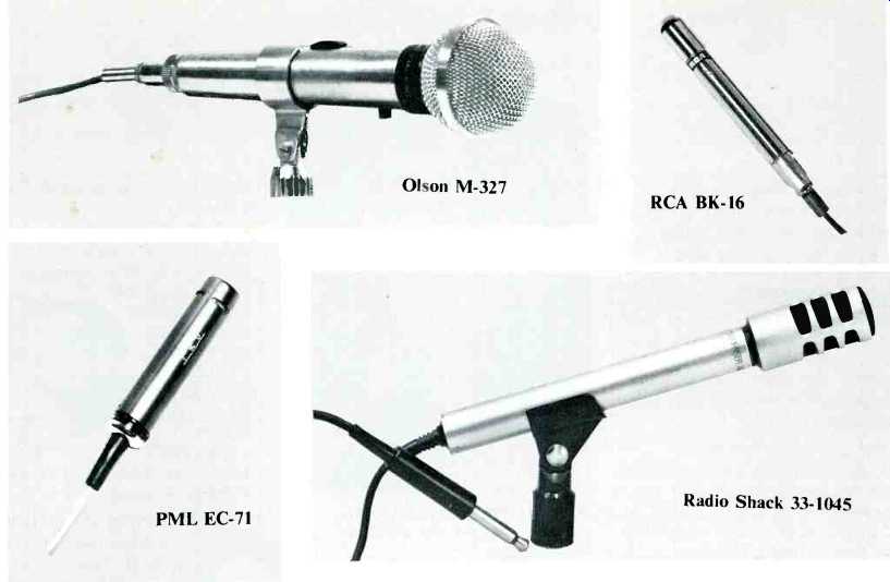

Piezoelectric Generating Elements
The diaphragm of a piezoelectric microphone is attached to a special material which produces an output voltage when bent or stressed. A piezoelectric generating element is shown in Fig. 1. Two types of piezoelectric materials are generally used. Crystal microphones employ a Rochelle salt crystal. Though crystal microphones have a moderately high output level, the crystal is easily damaged by heat and humidity.
Ceramic microphones, which use a barium titanate ceramic, are immune to heat and humidity but exhibit more average output level. Both crystals and ceramics, when designed for practical output levels, exhibit limited, rough frequency response, making them unsuitable for audiophile and professional use. Their low cost, however, makes piezoelectric microphones widely used in communications work.

Fig. 1-Piezoelectric generating element.
It is interesting to note that ceramic microphones with smooth, wide frequency response can be constructed--if low output levels can be accepted. Many precision sound level meters employ such microphones. However, the low basic output level coupled with additional losses encountered in a cable of practical length' make these ceramics unsuitable for more general use.
Conventional Condenser Generating Elements
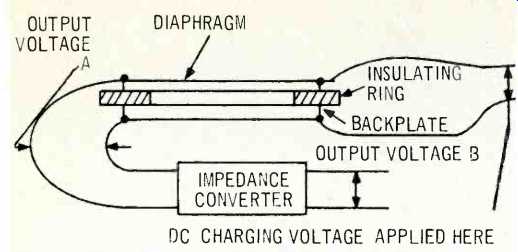
Fig. 2-Condenser generating element.
The diaphragm of a condenser microphone is a movable plate of a condenser or capacitor. A condenser generating element is shown in Fig. 2. If a condenser is charged or polarized by applying a d.c. voltage (usually 45 to 200 volts) across the diaphragm and backplate, motion of the diaphragm with respect to the fixed backplate produces an audio output voltage (Output Voltage A). Unfortunately, Output Voltage A cannot be put to practical use. The output impedance (the impedance "looking back" into the generating element) amounts, quite naturally, to a small capacitance.
Anything but a few inches of cable and a very high load impedance (500 Megohms, typical) would eradicate, for all practical purposes, the output of the generating element as well as its low frequency response. Therefore, an impedance converter, often of unity gain (no amplification), is built into each condenser microphone to "eliminate" the cable and provide the necessary high input impedance for the generating element. The output impedance of the converter is relatively low, essentially resistive, and quite suited for connection to the cables and preamplifiers of real life.
Condenser microphones burst on the domestic recording scene in the early 1950's, where their extended frequency response (with even a bit of a "haystack" at the high end) literally made "hi-fi" recording. Today, condensers, available in both flat and subtly-tailored response versions, are widely used in professional recording. Good commercial designs encompass 1, very high output level, 2, wide, smooth frequency response, and 3, excellent transient response. Several factors, however, have precluded the wider use of conventional condenser microphones in broadcast and public address fields: 1. high cost, 2, the rather fragile mechanical construction of many specific designs, and 3, the reliability problems associated with the external power supply and the internal impedance converter.
Today, solid-state technology has increased the reliability of conventional condenser microphones. Additionally, some designs may be successfully operated from battery-powered as well as a.c. powered power sources.
Electret Condenser Generating Elements
Despite improvements in conventional condensers, it would certainly be nice to permanently charge a condenser generating element at the time of manufacture and then throw away the bulky high-voltage power supply in the interest of lower cost, lower weight, and increased reliability. Then only a low voltage for the impedance converter would be required--from a small battery.
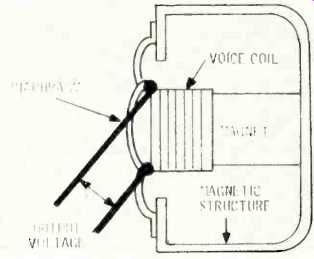
Fig. 3--Dynamic generating element.
Materials that will accept and keep a charge have been around for years-in the laboratory. These materials are called electrets. Of course, the factory-impressed charge is only useful if it is truly permanent. Experimental electrets of a few years ago would go dead in a matter of minutes in a humidity chamber. The humidity of a typical Midwestern summer day could do the same job in a few months. Today, new materials and charging techniques have changed this situation dramatically, but electrets are still not likely candidates for a hot car trunk in Florida! Under most conditions, performance is satisfactory: 30-day tests in 90 degree, 90% relative humidity environment revealed a permanent level loss limited to 3 dB. Oven tests at 120 degrees and above, with low humidity, showed losses of less than 1 dB. 120 degrees and high humidity, however, prove deadly.
Commercial electret designs now frequently combine 1, high output level, 2, excellent transient response, and 3, moderate-to-low-cost with 4, reliability that can at least be compared to, if not equal, that of dynamic microphones.
Remember, the very existence of a battery in the microphone is a potential headache that many sound installers will not want to contemplate. The probability of failure, however, is low enough to be tolerated in many broadcast and recording applications, professional and amateur alike. Frequency response can be essentially equivalent to fine dynamic and conventional condenser designs but most currently-available modestly-priced electrets suffer in such a comparison. More detailed comments on this and other comparisons are included in Part II.
Dynamic Generating Elements
The diaphragm of a dynamic microphone is attached directly to a coil of wire (voice coil) located close to a magnet. When the voice coil vibrates, an output voltage is produced. A dynamic microphone is shown in Fig. 3.
Practical dynamic designs can easily combine 1, adequate output level, 2, wide, smooth frequency response, 3, very good transient response, 4, very high reliability, and 5, moderately-low to moderately-high cost. This fortunate combination has made the dynamic microphone used more than any other type in broadcasting and sound reinforcement. Dynamics are also frequently employed by professional and amateur recordists. More detailed comments, comparing dynamic performance with that of other types, are contained in Part II.
[For a more detailed discussion of the effect of cable and load impedance on the output level of capacitive sources (piezoelectric and condenser generating elements), see Jim Long, "Layman's Guide to Microphone Specifications," AUDIO, Vol. 33, No. 8 (August 1969), p. 231. ]
Ribbon Generating Elements
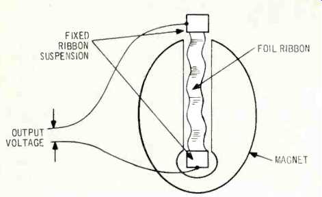
Fig. 4-Ribbon generating element.
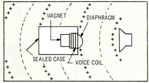
Fig. 5-Omnidirectional microphone.
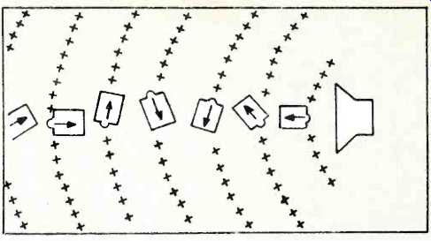
Fig. 6-Omnidirectional microphone at various angles.
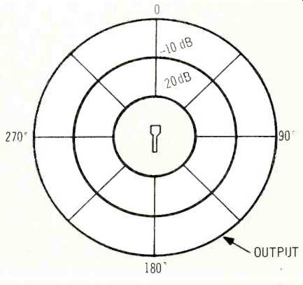
Fig. 7-Omnidirectional polar pattern.
Ribbon microphones are similar in basic principle to dynamics, except that a metal foil ribbon serves as both diaphragm and voice coil. A ribbon generating element is shown in Fig. 4.
Ribbon microphones were very much a part of the early days of broadcasting and recording. However, in order to obtain 1, adequate output level and 2, wide frequency response, these microphones employed ribbons that were-all at the same time-thin, light, soft, and floppy. One breath of air could alter the performance characteristics or render the microphone useless! Additionally, acceptable output level was obtained by using magnet material not particularly well suited to the large air gap inherent in a ribbon design. The finished microphone, then, was a rather bulky affair. Because of this ruggedness and size problem, unaided by any significant domestic innovation in ribbon design during the last 20 years or so, the availability of fine dynamic and condenser designs has virtually eliminated the use of ribbon microphones.
Some new designs are now available, however, which result in a microphone of very practical size and with greatly improved reliability.
Microphone Pickup Patterns and Some Implications.
A microphone's pickup pattern is three dimensional in character and shows how the microphone responds to sound from different directions. Omnidirectional microphones pick up sound from all directions. Directional microphones--of several specific types--reject or reduce sounds from their sides and/or rear. These types include cardioid (the most popular), bidirectional, and super-cardioid, the details of which will be covered later. In general, all generating-element types--condenser, ribbon, dynamic, piezoelectric--may be designed around any specific pickup pattern.
The advantages of directional microphones are fairly well publicized, but the compromises are not. The following review covers both aspects!
Making and Understanding an Omnidirectional Microphone
The sketches accompanying this section are cartoon versions of a dynamic moving-coil microphone. The general principles apply to all other generating elements as well. The case of the microphone in Fig. 5 is totally sealed, so that sound pressure can strike only the front of the diaphragm.
For instance (referring to Fig. 5), when a positive wavefront strikes the diaphragm, the pressure on the outside of the diaphragm is greater than that on the inside. The diaphragm moves in and microphone output results. Figure 6 points out the reasonably interesting fact that air pressure variations move the diaphragm in no matter how the unit is oriented with respect to the sound source. Microphone output is therefore constant regardless of orientation. Our totally-sealed microphone is an omnidirectional microphone!

Fig. 5--Omnidirectional microphone.

Fig. 6--Omnidirectional microphone at various angles.
Showing the Omnidirectional Pickup Pattern
The pickup pattern of an omnidirectional microphone may be thought of (though a bit frivolously) as an inflated balloon with the microphone at the center. This at least emphasizes the three-dimensional nature of a pickup pattern, but is a bit hard to reconcile with the two-dimensional world of the printed page. If we cut out balloon in half, we produce the standard two-dimensional representation of a pickup pattern-the polar pattern or polar response. Figure 7 shows the polar pattern for an omnidirectional microphone. Note the orientation of the microphone, at the center, aimed at 0° for reference. The heavy circle at the circumference of the polar pattern represents microphone output and shows that no loss in output (in dB) is experienced as a constant-output sound source moves a full 360° around a fixed microphone at a fixed distance from the microphone. Polar patterns are often described as too formidable for consideration, but a few moments study will greatly enhance your knowledge of what a microphone can do for you!
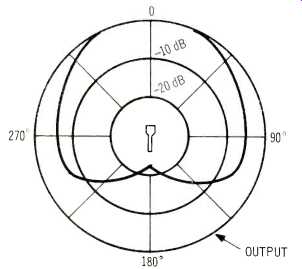
Fig. 8-Cardioid polar pattern.
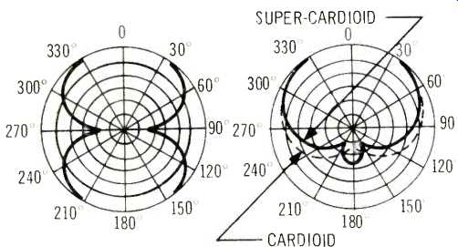
Fig. 9-Bidirectional and super-cardioid polar patterns.
Polar Pattern for Directional Microphones.
The output line for a directional microphone departs, at some range of angles, from the constant-output circle of the omnidirectional microphone. Figure 8 shows this condition for the most prevalent type of directional microphone--a cardioid, meaning "heart-shaped." A cardioid polar pattern is typically 6 dB down at 90° to either side of the reference, 0° axis. Output then decreases further to a minimum (15 to 25 dB down) at the rear (180°). Despite the rejection of sounds from the sides and rear, it should be noted that a cardioid's output is essentially constant just like an omnidirectional--over a relatively wide 80° angle! Don't expect any ordinary kind of directional microphone to ferret out a single voice in a crowd.
Other frequently-encountered directional types are shown in Fig. 9. The bidirectional or figure-eight pattern suppresses sound from the sides but is equally sensitive at the front and rear. The bidirectional pattern is inherently produced by a ribbon generating element. An infinite number of stages between cardioid and bidirectional are possible. One such stage that has been found useful is the super-cardioid. The super-cardioid has two nulls at 150° off axis with somewhat greater rejection at the sides and just to the rear of the sides, compared to a standard cardioid.
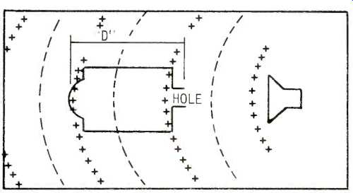
Fig. 10-Single-D cardioid microphone with source at rear.
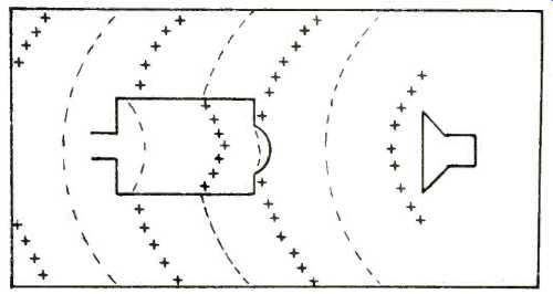
Fig. 11-Single-D cardioid microphone with source at front.
Making a Cardioid Microphone
In delightfully simple terms, a cardioid microphone may be made by piercing a hole in the case of a sealed omnidirectional microphone. Now sound pressure is permitted to contact the diaphragm from the rear as well as from the front, as shown in Fig. 10. Diaphragm motion is closely related to the pressure difference. This type of cardioid microphone is often called single-D, for the single effective acoustic distance between the front and rear openings.
Figure 10 shows the cardioid with the sound source at its rear. This representation would make an acoustician cringe, but serves to remove the specter of vector diagrams, etc., and elicits the response "Gee, I see how it works!" With sound coming from the rear of the microphone, diaphragm motion is neutralized by opposing sound pressures on both sides simultaneously. (Note the "plus" sound pressures on both sides of the diaphragm). No output results.
However, with sound originating from the front, as shown in Fig. 11, a "minus" pressure is present at the rear of the diaphragm at the very same time a "plus" pressure appears on the front. Both pressures are trying to move the diaphragm "in" so diaphragm motion can occur and output results.
Why a Directional Microphone?
Compared to an omnidirectional microphone at a given working distance, rejection of sound from the sides and rear of a directional microphone:
1. Reduces reverberation. If a recording with an omnidirectional microphone sounds too distant and lacks presence, use of a cardioid microphone will produce a substantially tighter, brighter sound.
2. Reduces unwanted noise. When recording a voice in an environment full of random noise (such as a factory), switching to a directional microphone will substantially reduce the level of noise with respect to the voice. In other words, the directional microphone provides in improved signal-to-noise ratio. The level of discrete noises (a gurgling radiator, refrigerator, compressor, tape recorder, motor, etc.) can also be reduced if the "dead" area of the microphone's polar pattern is aimed at the offending noise source.
3. Reduces feedback. The level provided in a room by a sound reinforcement system will increase when a good directional microphone is used, especially when direct sound from the loudspeakers strikes the "dead" portions of the pickup pattern.
The effect of a directional microphone can be put another way: if an omnidirectional microphone is providing satisfactory pickup at a given working distance, a directional microphone will give the same results at a greater working distance. A cardioid microphone provides an increase of 1.7 times, as shown in Fig. 12.
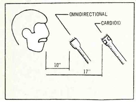
Fig. 12-Working distance comparison.
Compromises in Single-D Cardioid Performance
Here are three unfortunate compromises, compared to an omnidirectional:
1. A cardioid is significantly more susceptible to "breath popping."
2. A cardioid is significantly more susceptible to mechanically induced noise (ring clankings, cable thumpings, foot stompings, etc.).
3. A cardioid has a frequency response that is rougher and rolled-off in the extreme bass.
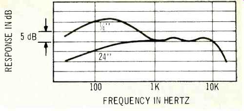
Fig. 13--Single-D proximity effect.
All three problems can, of course, be attacked by careful design, but success is rarely if ever total and is often accompanied by increased cost and/or other performance compromises. The cardioid compromises are basic enough to be found in many, many commercially-available designs.
Proximity Effect in Single-D Cardioids
The simple single-port or single-D cardioid has a bass response that varies strongly with working distance. As shown in Fig. 13, the bass response at one-quarter inch is boosted fifteen dB over the response at 24 inches and beyond.
Proximity effect can be a boon or a boondoggle in many applications but mostly it has been a mysterious variable of which most microphone users are not aware. Bass-boosting proximity effect, at the pleasing end of things, gives a "robust" quality to speech and "free" gain-before-feedback in close-up, hand-held sound reinforcement situations. However, these results must be balanced against a decrease in clarity, due to the masking effect of the bass boost, as well as the problem posed by yet another variable for the already harried sound man to face.
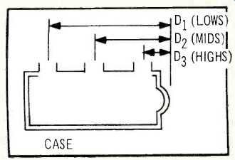
Fig. 14--Variable-D cardioid microphone.
Eliminating Proximity Effect
In single-D cardioids, bass-boosting proximity effect occurs because the pressure differences to which the diaphragm is sensitive becomes extraordinarily large for close low-frequency sound sources. Variable-D® design, where several entrances are provided to the rear of the microphone diaphragm, is shown in Fig. 14. Variable-D design employs multiple ports, with high frequencies entering the port closest to the diaphragm, mid frequencies entering midway along the length of the microphone case, and low frequencies entering the port farthest from the diaphragm. Variable-D construction maintains a much more constant pressure difference on the diaphragm as frequency is reduced for both close and far sound sources. Proximity effect is for all practical purposes eliminated, as shown in Fig. 15.
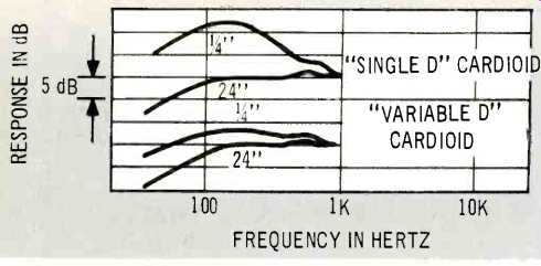
Fig. 15--Proximity effect comparison.
Continuously Variable-D is a refinement that permits more uniform frequency and polar response. The three ports of Variable-D design are replaced by a long slotted entrance which has a continuously varying frequency acceptance along its length, as shown in Fig. 16.
Variable-D and Continuously Variable-D are patents and registered trademarks of Electro-Voice, Inc.
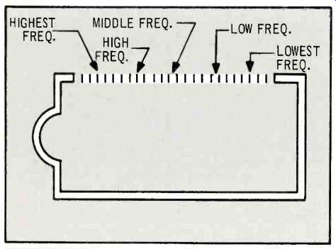
Fig. 16-Continuously Variable-D microphone.
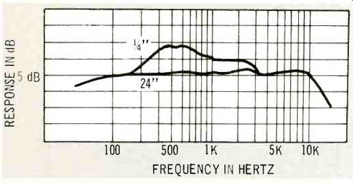
Fig. 17-Proximity effect of high frequency head in two-head cardioid design.
Reduced Pop and Shock Sensitivity
Variable-D design substantially reduces susceptibility to breath popping and mechanically-induced shock, compared to single-D designs. The Variable-D, then, tends to combine many desirable omnidirectional characteristics with the cardioid's noise, reverberation, and feedback-reduction advantages.
Two-Head Cardioid Designs Alter Proximity Effect
Some cardioids employ a second generating element, with a crossover network between the two at about 250 Hz. The rear entrance to the low-frequency head is at the rear of the microphone case, virtually eliminating the low frequency proximity effect, in the area broadly centered around 100 Hz.
The remaining proximity effect of the high-frequency head, located above the 250 Hz crossover frequency, is displayed in Fig. 17.
Microphone Impedance Microphone impedance refers to the impedance seen when electrically "looking back" into the unit's output terminals.
Microphones are usually described as either high impedance or low impedance. Low impedances typically range from 50 to 250 ohms, or perhaps to 600 ohms, while high impedances range from about 25,000 ohms on up to several megohms.
Some medium impedance microphones (several thousand ohms) exist but the inputs appropriate to the characteristics of these microphones have largely disappeared.
A microphone's impedance may be capacitive, as in piezoelectric designs, or resistive, as in ribbon, dynamic, and condenser (after the impedance converter) designs. This difference is important, because it determines the effect of cable and preamplifier loads on microphone output level and frequency response. Since piezoelectric microphones are seldom used for high-quality work, however, the discussion of resistive-source microphones is adequate here.
High impedance resistive-source microphones have their high frequencies drastically rolled off by any reasonable length of microphone cable: a 20-foot cable might put response down 6 dB at 10,000 Hz! In contrast, low-impedance resistive source microphones may be used with hundreds of feet of cable with essentially no loss below 20,000 Hz. The moral, of course, is to avoid high-impedance microphones if at all possible! High impedance microphones do have higher output level.
High impedance is attained by having a large number of turns on a voice coil or a transformer built into the microphone. Having a large number of turns in the magnetic field simply produces a higher output voltage than having a small number of turns: the increase is approximately 20 dB into an open circuit (approximated by having the microphone terminated by an impedance at least ten times its own impedance value). It is worth noting that the higher output voltage inherent in high-impedance microphones is not immediately obvious from a casual inspection of their sensitivity rating. The raw numbers come out about the same for both impedances, such as "-55 dB," but this is because there are two basically different rating schemes commonly employed for high- and low-impedance types. These differences will be discussed later.' A good way of achieving high output voltages from low impedance microphones, where the microphone input demands it, is to employ an in-line transformer (commonly called a "line matching transformer") at the equipment end of a low-impedance microphone's cable. The high-impedance cable coming out of the transformer can be very short so that no high-frequency rolloff occurs.
----For a detailed discussion of the two sensitivity rating methods, including calculation of the actual voltage delivered to a given load, see Long, AUDIO, pp. 61-63.
(Audio magazine, Dec. 1972)
Also see:
MICROPHONES--Quo Vadis? (Apr. 1972)
Microphones: Start With the Basics (Apr. 1985)
A Microphone Primer: Conclusion (Feb. 1973)
Mike Technique and Sound Effects (Dec. 1974)
Electro-Voice microphones (Jan. 1973)
= = = =