
by George W. Tillett
American hi-fi enthusiasts seem always to have had a special and high regard for audio equipment from England, almost as if the gear were the work of an older, wiser brother whose abilities and intentions were respected, but not quite fully understood. England has also had and continues to have a succession of highly interesting innovators and inventors, whose products are the stuff of myth or legend and whose exploits and foibles bear frequent description.
Names such as Alan Blumlein, Percy Wilson, and Gilbert Briggs come to mind. Several such folk are currently active on the British hi-fi scene, so we thought it would be interesting to have Contributing Editor George W. Tillett, a Brit who's been transplanted, tell us about his trip to the Harrogate Festival, England's consumer hi-fi show, and to the facilities of several leading audio equipment manufacturers. --E.P.
Harrogate, the scene of the August International Festival of Sound, is a delightful spa resort in the north of England renowned for the beautiful gardens and flower displays. Compared to U.S. Shows, the Festival was much smaller with about 125 exhibitors. On the other hand, it was more leisurely and friendly with many of the demonstration rooms in such Dickensian hostelries as The Old Swan, The Crown, and St. George. Unfortunately, most of the demonstrations were too loud and nearly all were of pop music with a heavy bass line. However, there were some notable exceptions, and some excellent sound was heard from KEF, Quad, Castle, Wharfedale, Rogers, and Mission. Both Pioneer and Philips were showing LaserDisc players, although they are not yet available in the U.K. The JVC VHD player, sponsored there by the EMI-Ferguson group, was scheduled to be released this month (January) but I understand it has been postponed until June.
One of the most interesting items on display was a turntable called The Rock from Elite. It uses a pivoted arm with a tiny paddle at the cartridge end which dips into a silicone fluid in an arc-shaped trough. Thus, the arm is really a damped beam instead of a free cantilever. The viscous damping is claimed to reduce the arm resonance by some 15 dB as well as providing extra stability. I can testify to this feature, as the base and platter could be pounded quite hard before tracking was affected. The motor is a servo-controlled d.c. type and the rigid epoxy-concrete platter turns in a viscous fluid bearing.
Garrard broke with tradition by showing a complete range of components speaker systems, tuners, amplifiers, turntables the lot. As some are made by their Brazilian affiliate, we may well see some of these items over here later. I didn't get a chance to hear them but I must say that their styling was most impressive.
Tannoy, now under new ownership, also broke with tradition as they were proudly demonstrating a bookshelf loudspeaker measuring only 20 x 14 1/2 x 10 inches using a 10-inch coaxial driver.
The model number is the SRM 10B. Center of attraction at the Wharfedale booth was a computer display programmed to select the best loudspeaker system for any or almost any listener.
Details to be punched in include the type of music most often listened to (classical, opera, pop, rock, etc.), amplifier power, room size (length, height and width), and so on. After telling the computer the most important parameter the maximum amount of money available the recommended model numbers are flashed on the screen.
Toshiba was showing a new AM/FM tuner with no fewer than 30 presets, and I noted that they now have three cassette decks boasting ADRES noise-reduction circuitry which is an encode-decode system giving 30 dB signal-to-noise improvement.
One of the reasons for this European trip was to visit some of the better known British loudspeaker companies. First on my list was Wharfedale as they are located quite near Harrogate, in a town with the inappropriate name of Idle. As most readers know, the company was founded by the late Gilbert Briggs, famous for his books on audio which were notable for a down-to-earth style and enlivened with a droll Yorkshire humor. The company began operations in 1932, and it has an impressive list of "firsts" which include moving-coil headphones (1947), a two-way speaker with crossover (1945), and a speaker unit with a roll type surround (1955). They were the first to use laser holography for the study of speaker cone behavior and the first to make planar high-frequency units, at least commercially. I believe they were also the first to stage live-versus-recorded music concerts. In fact, I was privileged to help in one such affair in London's Festival Hall back in 1957 or thereabouts.
After a discussion with Wharfedale's Technical Manager, Ken Russell, and some of the senior engineers, I was taken on an inspection tour of the 400,000 square-foot Idle facility. The Plant Manager was justifiably proud of the large, well-equipped cabinet-making facility, and he pointed out that most cabinets are finished with wood veneers, not vinyl. Great care is taken to match them, and each cabinet's grain is a mirror image of its partner's. In the test department, bass drivers were being checked with 300-watt pulses a necessary precaution in these days of super power amplifiers. I was told that the biggest problems did not have to do with rock, organ or disco music but with reggae! As mentioned earlier, Wharfedale pioneered the use of laser holography, and the original technique was to illuminate the speaker cone so the reflected light would fall onto a special photographic plate where it would be combined with the reference beam. When the plate was developed, the photograph could be viewed by laser light to show the interference patterns. Although nodal patterns can easily be seen, frequency aberrations are not that simple to interpret and the photographic process is time-consuming.
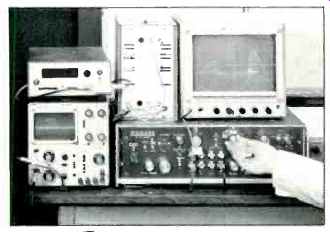
One present Wharfedale system is called SCALP, a hair-raising acronym which stands for Scanned Laser Probe. Here's how the system works. Light from the laser is divided into two beams, one is sent to the loudspeaker being tested and the other is sent to a rapidly rotating disc which changes its frequency by 10.7 MHz. Both beams are returned to the beam splitter which then sends a composite beam to a photocell. The two components beat with each other to produce a signal which is amplified and passed to an FM discriminator and an X-Y plotter. When the speaker cone is stationary, a steady d.c. signal is generated, but as the cone moves forwards the light reflected is shifted upwards in frequency. Conversely, when the cone moves back, the reflected frequency will be lower. The beam falling on the speaker cone passes through two mirrors connected to the magnetic coils; one drives the beam across the cone while the other scans vertically so the plotter builds up a three-dimensional picture of the cone's vibration. Using a single frequency, the SCALP process takes 15 minutes to build up a complete picture.
A variation of the system is called FRESP or Frequency Slice Plot, and its inventor, Dr. Peter Fryer, said it was most useful for pinpointing the troublesome regions of a speaker cone's behavior. The equipment is set up in the same way as SCALP, but the vertical scanning mechanism is turned off so each curve plotted is of the same horizontal slice across the middle of the cone. Instead of inching the laser beam from the bottom to the top of the cone for each separate trace, the frequency fed to the speaker is changed between plots starting at the highest frequency desired and going down in small steps.
This results in a plot having the same width from top to bottom, the width corresponding to the central slice across the middle of the cone. Thus, each separate curve illustrates the behavior of this slice of cone at a different frequency.
Alternatively, each curve can be made with a frequency sweep so the effect is a change in "vision angle," as each curve represents the behavior of the cone at all frequencies. It is also possible with FRESP to plot the cone behavior in three dimensions when each slice is at the same frequency but at a different phase. In fact, curves at any phase angle can be made and complete vibration cycles can be studied. Finally, both SCALP and FRESP systems have phase reversal capabilities so "holes" in the complex curve mass can be changed into "hills" if desired.
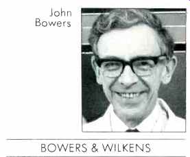
John Bowers of BOWERS & WILKENS
Bowers and Wilkens, or B&W, commenced operations in 1966, and they are based in the attractive seaside town of Worthing on the south coast. The company, headed by the energetic John Bowers, now has three plants with a modern well-equipped laboratory. Computers play a large part in production and design functions, and I noticed that access to a sophisticated PDP 11/40 was available in a number of areas. The B&W laser system as applied to cone technology has been described at some length in these pages (August and September, 1981), and it is sufficient to say here that it is a little different from Wharfedale's system, although both employ a Doppler principle.
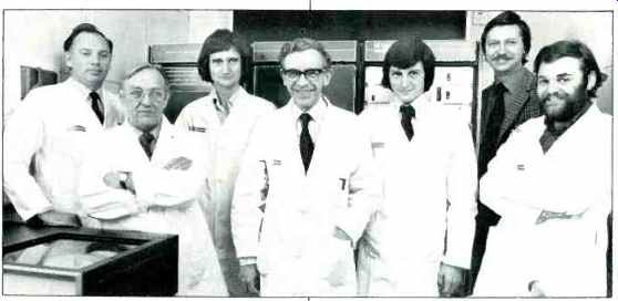
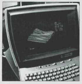
But laser techniques can be useful in other areas, and Chief Engineer Dr. Glyn Adams made use of it to improve the enclosure housing the midrange unit in the Series 800 loudspeaker systems.
The original cabinet was made of wood and caused a subtle coloration. As the possible radiating area of the complete enclosure is many times that of the cone area, it is obvious that it must be as acoustically dead as possible. Using a laser system as a "massless accelerometer," B&W tried all kinds of materials as linings bitumin, lead sheeting, pads as well as various bracing combinations. Eventually, the answer to the problems was found in a glass-reinforced cement with an outer skin of molded polystyrene. The improvement in the critical 300 Hz to 3 kHz region is over 10 dB, bringing cabinet vibration down to 60 dB below the cone output. The difference was quite audible in listening tests although it would not be easily discernible in normal frequency response measurements. But pulse tests and non steady-state analysis tell a far different story! One example of computer use pointed out by Dr. Adams is the solving of a crossover design equation with 13 variables in a matter of minutes. This facility could save a lot of headaches and man-hours, although it might tend to make the engineers rather lazy! B&W has come a long way in a relatively short time, and one reason for their success has to be the emphasis on up-to-the-minute technology but I was even more impressed by the highly qualified, dedicated staff. Working conditions are excellent and even the employees on the production line are made to feel part of the company. Perhaps that's the essential secret of B&W's success.
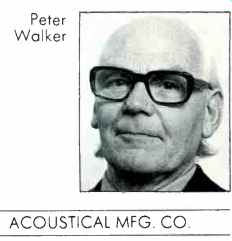
Peter Walker -- ACOUSTICAL MFG. CO. (Quad)
My next visit was to Quad, as the Acoustical Manufacturing Co. is often known, which is located about 70 miles northeast of London, in the small country town of Huntingdon. The company was founded way back in 1936 by Peter Walker who is now ably assisted by his son Ross. The name Quad has nothing to do with four; it originated with an amplifier which was called Quality Unit Amplifier Domestic. Incidentally, the Quad amplifier, which was introduced in 1951, was the first to use an ultralinear power stage where the cathodes of the output tubes were taken to taps on the transformer. The Corner Ribbon speaker system also made its appearance about this time, and I note from an advertisement in September 1951 that "Reflections from the back radiation add to the area of sound so now it appears to emanate from an opening of eight to ten feet square." The well-known Quad full range electrostatic loudspeaker was introduced in 1957, and it was soon accepted by broadcasting authorities, studios, and loudspeaker engineers as a reference standard. It is still being made.
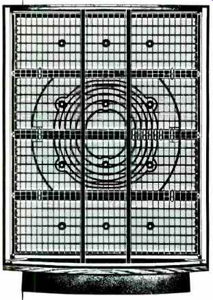
However, in 1963 work commenced on a revised version which is now in production. This is the ESL-63, known among acronym-loving cognoscenti as Fred or Full Range Electrostatic Doublet. I had heard these long-awaited models at the last Chicago CES but I was eager to listen to them under better conditions as well as to see how they are made.
Peter Walker explained the basic concept as follows:
"An ideal loudspeaker can be imagined as some form of pulsating or vibrating sphere, neither of which is practicably realizable with precision if any reasonable power output is required. Suppose, however, we were to plot the air particle velocity components normal to a plane interposed between an imaginary ideal source and the observer. If we now substitute a plane surface with the same distributed velocity pattern, it follows (if the surface is sufficiently large) that a replica of the curved wavefronts would be created and we would have an accurate acoustic 'picture' of our ideal source for any position of the observer." Then, holding up a large sheet of thin, transparent plastic, Peter said, "You will hear no difference to the sound of my voice when I speak through it."
Well, obviously the best way to drive a large, low-mass diaphragm is by electrostatic means but controlling it to produce a spherical waveform posed some problems. The diaphragm in the ESL-63 measures 30 x 24 inches and is suspended between two sets of electrodes made from perforated copper-coated plastic. This diaphragm is only 2 microns thick (or thin), and it is coated with a conductive material. A polarizing voltage of 5 kV is used, but the outside plates are at ground potential. Now, here is where the construction differs from the original model: Each of the copper plates is cut to form circular rings shown in the photo.
The audio signal is fed sequentially to each set of rings by a series of inductors and capacitors which form delay lines.
The result is a waveform which is coherent in terms of phase and frequency, since this delayed signal application causes a relatively large diaphragm to act as a point source.
The radiation pattern is arranged to be substantially constant with frequency. In a normal listening room, the excitation of both horizontal modes is 3 dB lower than with an omnidirectional 'source, resulting in a better stereo image. Each coil consists of 12,000 turns of fine gauge wire, and the delay per section is 24 µS which is equivalent to a path length in air of just over 3/8 of an inch. It must be emphasized that the circuit is very complex; for example, there are several crossfeed capacitors. The high voltage generator circuit is a fairly conventional cascade arrangement. A neon lamp is connected in a relaxation circuit so the flashes serve as an indicator.
There are two protection circuits, one a "soft clipper" which reacts to peaks over 40 volts, while the other senses ionization which could be a prelude to a "flashover." The high-frequency noise radiation that happens just at the start of ionization is picked up by an antenna which is closely coupled to the high-voltage section, and the signal is amplified and passed to a timer which then fires T1 to short circuit the audio input. Very ingenious....
The units are amazingly constant, and a favorite trick of Peter Walker's is to place a microphone in between a pair fed with a square-wave signal of around 1 kHz. Microphone output is displayed on a 'scope, and when one channel is phase-reversed, a slight touch of the amplifier's balance control and the square wave is nulled out it just completely disappears!
Each subassembly is thoroughly tested and the electrostatic panels are checked for capacitance, Q factor and other parameters. The final test proved to be quite simple but impressive for all that. After checking the frequency and impedance against a standard 'scope curve, the aforementioned nulling technique is then used with a reference loudspeaker. This kind of test is only possible because of close tolerances at every manufacturing stage.
I noticed that the assemblers work in teams which produce complete units (amplifiers, tuners or speakers), which is obviously more satisfying than mass-production methods where each worker continually solders the same six wires or whatever.
How does the ESL-63 sound? Compared to the original model (one of mine, by the way, is number 51), it has an extended bass response but I think the most spectacular improvement is in the smooth radiation pattern. The vertical angle is much greater, and the stereo image has a sense of spaciousness and depth, while the listener is not so restricted to the "stereo seat." Overall sound is well-balanced and completely neutral.
Some years ago, Peter Walker was asked whether he was satisfied with the ELS. He replied, "No, we think our loudspeaker is very poor but we think most of the others are much worse. But you can put a good moving-coil loudspeaker and an ESL side by side and … There's much less difference now than there was 20 years ago." I didn't ask him whether he thought the ESL-63 was perfect, but he would probably answer with a roundly diffident, "No, but it does make a nicer noise than any of the others!"
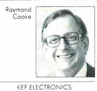
Raymond Cooke --- KEF ELECTRONICS
The last plant on my list was KEF, situated near Maidstone in the County of Kent about 40 miles south of London. The company was formed by Raymond Cooke in 1961 and soon acquired a reputation for enterprise with their innovative designs. They were the first to make a bass driver with a flat plastic-foil sandwich diaphragm and the first to use Melinex (Mylar) for a low-mass dome tweeter. In 1966, KEF introduced a driver using Bextrene hard plastic cone material, and since then many thousands of these units and the flat diaphragm models have been sold to other speaker manufacturers in many countries. Needless to say, computer techniques play an important role in KEF designs, and some two years ago, a unique computerized production system was installed. Unfortunately, I was unable to see the plant in operation, but I did have discussions with Raymond Cooke and some of his engineers. Basically, the speaker units are not tested with frequency sweeps but by a digital method based on the relationship between the frequency response and impulse response as expressed by the Fast Fourier Transform (FFT). In other words, a loudspeaker's frequency response and other data can be calculated by a computer if the impulse response is known. The advantages are that it is much faster than frequency measurements, less critical of room acoustics and, once the impulse response is obtained, all other parameters including transient behavior can then be analyzed.
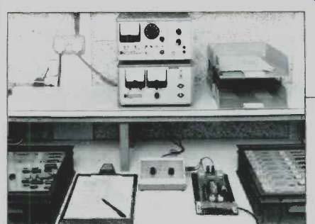
The unit under test is placed near the center of the test room and fed with a series of pulses. The resulting waveform is picked up by a microphone and then passed to an analog-to-digital converter and a spectrum analyzer which has a CRT display for monitoring before the data is stored in an HP-7900A magnetic disc memory. To maintain a good signal-to-noise ratio, the pulses are repeated 64 times and the responses averaged by the computer. Drive units are usually measured in batches of 94, and the data is transferred to the computer which then compares the sensitivities and responses at 1/8-octave points before providing a printout listing matching pairs.
If, for example, the units are for a three-way system like the 105, the process is repeated for the other two drivers, and finally they are matched in sets of six. Crossovers are matched within 0.2 dB so the complete loudspeaker systems do not differ more than 0.5 dB from its partner in the pair.
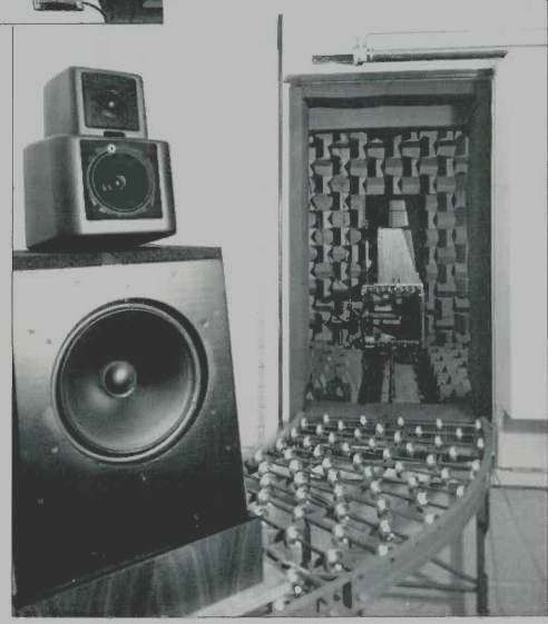
The same FFT measurement technique is used by the design engineers. For example, cabinet resonances can be investigated, and optimum phase locations of the driver units can be made. A further development of the system is the production of three-dimensional response curves which are made by simulating delayed response curves. As Laurie Fincham, KEF's Chief Engineer, has pointed out, steady-state response curves do not show a loudspeaker's behavior with transients, such as occur naturally in music.
Like other manufacturers, KEF has broadened their range to include low-priced models. For instance, the Cantor II, a new two-way system, costs only 100 pounds a pair (about $185) in the U.K.! Because of the experience and technology involved, it is safe to say they will outperform systems put together on a "hit or miss" principle and costing a lot more.... I would have liked to visit Celestion as I know they are well advanced in laser analysis, but time was pressing and I had to get back to sunny Florida. Perhaps I'll make it next year!
(adapted from Audio magazine, Jan 1982)
= = = =
KEF 105 Series II Loudspeaker (Feb. 1982)