By Ivan Berger

above: A view inside the tower, showing the antenna bays and some of the
r.f. plumbing.
[....missing content, to be added...] modern dairy, a room full of anodized aluminum cabinets connected by fat copper transmission lines that look more like pipes than signal cables.

Fig. 1--Block diagram of the nine-station combiner.
As Fig. 1 shows, the combiner is not so much a complex circuit as one simple circuit repeated nine times, once for each transmitter, feeding into another circuit that couples it to the antenna. Each transmitter's output first passes through a dual directional coupler, a circuit which allows the signal that the transmitter feeds into the combiner to be monitored automatically.
The signal then enters the combiner's input patch panel, which allows the combiner to be temporarily bypassed in case of failure. (For broadcasters, staying on the air, even when equipment fails, is vital.) The lower left patch of each panel provides access to the transmitter's output, so that the filter section (the input and output hybrids and the cavity module) can be bypassed in case of trouble. The lower right patch provides access to the filter section; a replacement transmitter would be plugged in here. The upper patches of each panel merely provide a signal path between the panels, eventually feeding to the broad-band (unfiltered) emergency input at the first output patch panel.
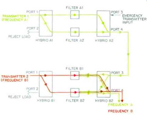
Fig. 2--How the combiner's hybrids and filters work.
The signal from the first transmitter (Frequency A) is split by hybrid A1 and passes through filters A1 and A2, which are tuned to that frequency; then its two halves are rejoined at the broad-band output (port 4) of hybrid A2. This signal then passes through the combiner system's broad-band line to the broad-band input (port 3) of hybrid B2, the second transmitter's output hybrid. Hybrid B2 splits the Frequency A signal and passes it to filters B1 and B2.
Since these filters are tuned to Frequency B, they reflect the Frequency A signal back into hybrid B2, where it joins Frequency B at port 4. The combined signals then go on to the next transmitter in the chain.
In the output patch panels, the broad-band signal--the sum of all the signals combined up to that point--is fed via the upper patches into the broad-band input port of a station's filter section, where that station's signal is combined with the ones already on the line. The new combination is then fed out, via the lower patches, to the next station's broad-band port.
The Filter Section
The filter sections each have three parts, an input hybrid, a cavity module, and an output hybrid. A hybrid, in broadcast terms, is a four-port power divider. Power fed into any port of the hybrid is split evenly between two other ports; no power flows into the remaining port. The hybrids used in the Miami installation are a quadrature type, meaning that the two outputs differ in phase by 90°.

above: From its new antenna site, WINZ-FM's signal covers about
5.5% more area, and reaches nearly 8% more people, than it did from downtown
Miami.

above: Since moving to the tower, classical station WTMI has improved
its audio quality by replacing telephone program links with a microwave
relay dish (left) and a satellite link to the Mutual Broadcasting Company's
Metropolitan Opera feed (right).

Downtown Miami, showing former WTMI antenna (building at
left) and antenna formerly shared by WINZ, WLVE, and WHQT (building near
center). Signal reflections from surrounding buildings caused multipath
distortion and dead spots.
There is a 50-ohm "dummy" or "reject' load on the fourth port of the input hybrid, necessary to keep the hybrid's impedance balanced. In a perfect hybrid, no power would reach this load resistance, but in the real world, some does both from the module's own transmitter and from other transmitters in the combiner system. Typically, the power from each transmitter on the system is not that much; for 20-kilowatt transmitters, it should be about 10 to 20 watt's from the module's own transmitter, plus a few watts from each of the system's other transmitters. The resistors used in the combiner have rated capacities that range from 100 to 1,000 watts, while the antenna reject load resistors are rated at 5 kilowatts.
All are cooled by oil baths. Their temperature is monitored by an electronic system teat sounds an alarm and shuts off that nodule's transmitter if there is an abnormally high level of power dissipation across them.
The cavity modules are where the filtration takes place. The "cavities" are actually resonators formed of quarter wave sections of 75-ohm coaxial cable, one end shorted and the other open-circuited--equivalent to such acoustic cavity resonators as closed organ pipes, soda bottles, and vented speaker enclosures. A temperature-compensation system keeps the length and tuning of each resonator constant regardless of changes in temperature.
There are eight such cavities per combiner module, divided into two parallel paths. The input hybrid divides its input power equally between the two parallel paths and creates a phase difference of 90° between the two. The output hybrid recombines the two halves of the signal, putting them back in phase with one another at the terminal which leads to the next transmitter module on the string, and cancelling any signals which might otherwise feed back through the output port to the previous transmitter module. This process transfers nearly all of the transmitter's power into its broad -band line, which eventually feeds the combined signal into the antenna.
The broadband line conducts the first station's signal to the broadband input of the second station's output hybrid, which splits that signal and feeds it to the second station's two filter modules (Fig. 2). Because these modules are tuned to pass only the frequency o the station operating through them, the power from the broadband line reflects off the two filter sections back into the output hybrid. This reflected broadband power recombines in that hybrid and is transferred back into the broadband line towards the antenna. Meanwhile, the second station's power is fed through its combiner module int the broadband line, exactly as the first station's power was fed by its module. In the broadband line, we now have the power from two stations travelling toward the antenna, each unaffected by the other. The same operations are repeated for all the other modules in the combination system.
This quadrature technique allows the cavity nodules to be smaller and more efficient, because each filter section handles only half its transmitter's power. According to Richard L. Edwards, chief engineer of Guy Gannett Broadcasting (which owns WINZ and the antenna lower facility), if the transmitter's Entire output were fed through a series string of combiners, "the cavity resonators would be enormous, hot, and higher it insertion loss."
The two resonators are each tuned to their station's center frequency. This technique red ices losses, not only making the system more efficient but keeping the resonators more sharply tuned.
Even this filtration is not enough for static ns that are very closely spaced, such as WLVE and WTMI (93.9 and 93.1 MHz) and WSHE and WMXJ (103.5 and 102.7 MHz). These stations are as close as the FCC allows in a give i market, with carriers 0.8 MHz apart and sidebands extending to within 0.4 MHz of each other. It is very difficult to make filters which have the bandwidth and phase linearity to pass the desired station without distortion and which also provide sufficient isolation from closely spaced signals.
The hardest problem to control is the group-delay difference mentioned earlier. The group-delay curve of the band-pass filter sections is a parabola, symmetrical around its center frequency. When two transmitter modules' frequencies are dose, their curves become lopsided, greatly increasing the group-delay difference across each station's channel.

above: The combiner room of the tower in 1985, when only five FM stations
and one TV station were broadcasting from there. The "pipes" are
large-diameter coaxial cables.

above: The combined signals of all the FM stations on the tower
flow through the patch panel at left into the hybrid at center. This hybrid
divides the signal in two, sending each half, via one of the patch panels
at right, to a separate half of the antenna. If one part of the antenna
fails, the other can continue operating.

above: Richard L. Edwards, director of engineering for Guy Gannett
Broadcasting, in the new combiner room.
The solution to this problem is to provide "equalizers"--filter cavities tuned to cartel these group-delay effects (she we in Fig. 1 between the input patch panels and input hybrids for WLVE and WMMXJ). If the filter modules were simply connected in parallel, equalizers would be needed for the combiner-nod ales of both stations in each closely spaced pair. In the balanced 'combine: used in Miami, however, the output hybrid of the "downstream" channel (the one nearer the antenna) isolates that channel from group-decay effects caused by the "upstream" channel, so only the latter requires equalization.
Each equalization module, placed at the input of the upstream channel's combiner module, consists of an extra hybrid and two equalizer cavities.
These cavities are tuned to reflect the channel's power back into the equalizer hybrid. As they do so, they "pre distort" the signal's group-delay characteristics to compensate for the group-delay distortion that will occur when the signal reaches the downstream module of the closely spaced station pair. As a result, the distortion is cancelled before it can go down the line towards the antenna.
The Antenna Section
After the last transmitter's output has been combined with that of all the others, the signal passes through another patch panel to a final hybrid. The hybrid divides the signal into two portions, each feeding a different half of the antenna. This redundancy allows the stations to stay on the air (albeit with reduced power) should storm damage or other problems affect either half of the antenna. Because the hybrid's two output signals differ in phase by 90°, the leading-phase half of the signal must be delayed to let the other half of the signal catch up; this is accomplished by placing enough additional cable to delay the signal 90° between the leading phase output of the hybrid and its associated antenna half. The band separation filters allow each station's output to the antenna to be monitored from the system's control console.
Note that the antenna section also contains patch panels. These allow the entire signal to be fed to either half of the antenna, should the other half malfunction.
Performance
The Miami combiner more than fulfills most of its design objectives. "We get 80 dB of isolation between stations," Edwards says. "In the past, the rule of thumb was 28 dB. Further, nothing on either side of the signal will pass that can interfere with other stations.
Yet the waveforms are perfectly contoured within ±200 kHz of the main signal. We're flat within 0.3 dB, which means stereo separation will be better than on other systems-better than most single-station systems. Everything we've tested so far exceeds the limits of our measuring equipment." The original specifications worked out between the combiner's maker, the Shively division of Howell Laboratories, and its purchaser, Guy Gannett Broadcasting, called for a VSWR (voltage standing-wave ratio, a measure of impedance matching and power transfer between transmitter and antenna) of at least 1.1 to 1 over a range of ± 150 kHz around each station's frequency.
Frequency response was specified to be flat within 0.5 dB or less over a range of ± 200 kHz around each station frequency. Isolation between stations was to be 50 dB or greater at a channel spacing of 0.8 MHz. Insertion loss was to be no more than 0.3 dB per module, and group-delay differences within ± 150 kHz of each station frequency were to be kept within 50 nS or less.
When the system went on the air in 1985, with just five stations, most of those specifications were either met or exceeded by a wide margin. The combiner's VSWR was within limits over the specified ± 150 kHz range for one station, and within ±300 to 400 kHz for all the rest. Frequency response was flat within 0.1 to 0.2 dB, except for a 0.5 dB response drop at--200 kHz for one station that was closely spaced to another. Isolation between that pair of stations was 59 dB in one direction and 66 dB in the other; it ranged from 64 to 98 dB between all other stations.
Insertion loss was not quite up to spec, ranging from 0.31 to 0.64 dB, but it was below 0.4 dB for all modules but one. Group-delay differences ranged from the specified 50 nS down to a low of 30 nS. "We pushed them pretty hard on the insertion loss," says Edwards, "but it's still acceptable-and most of the other specifications are surpassed by a wide margin. There are systems still on the drawing board that don't do this well.
"What does this mean to the listener ? It means that whatever's being played in the studio, even a CD, is guaranteed to pass right through the system to the listener's receiver, with no audible degradation."
===============
Interview: Richard L. Edwards, WINZ Broadcast Engineer
By Lewis T. Fineman
Problems can be opportunities in disguise. Such was the case for WINZ-FM, Miami, which turned a problem with its antenna site into improved FM reception for millions of South Florida listeners. In the process, the broadcaster also increased signal reach and fidelity for itself and eight other stations. Here, Richard L. Edwards, director of engineering for WINZ-FM's owner, Guy Gannett Broadcasting Company, tells how it was done.
What is the history of this tower project?
About five years ago, WINZ-FM, the local FM station of the Guy Gannett Broadcasting Company, got wind that tall buildings were going to be put up in downtown Miami. We were concerned because we knew that these buildings would degrade our station's signal.
Where were you operating at that time?
We were on the top of One Biscayne Tower, which is right on Biscayne Boulevard in the heart of downtown Miami. We decided rather quickly that we had to find an alternate site. We looked at the possibility of going onto one of the taller buildings as they went up downtown, but we decided that wouldn't work because another building would just come along that was even taller. Any way you looked at it, our signal would be obscured.
We started looking at alternate sites to see if we could find a location to construct a 2,000-foot tower, which is the maximum height allowed by the FAA and FCC. We found nothing. Then we tried to work out an agreement with a tower that was already in existence near the Dade/Broward County line. But we ran into complications with the FCC because that would put us too close to an adjacent-channel station in Riviera Beach. We then started to look for land to build a shorter tower on, and found a piece of property after a two-month search.
When we found the land, we had FAA approval in 10 days for building a 1,049 foot tower. The FCC took longer: We filed our original application in October of 1982, and then re-filed after some changes in the laws. Final FCC approval to begin operations was given on January 31, 1985, and WINZ-FM was broadcasting from the tower by that afternoon.
While all this was going on, various other stations in the market were also applying to move from the downtown Miami area. They were receptive to moving with us when we found our location. This included WTMI, the local classical-music station, as well as other stations which had been located at our old site at One Biscayne Boulevard.
When we started building, we had commitments from five FM stations and one TV station. The other stations began broadcasting from the new tower, one by one, starting the day after we did. [Editor's Note: There are now a total of eight, with another being added this summer.]
Did the tower have to be specially engineered for the site?
Oh, absolutely. There is no such thing as an off-the-shelf tower of this size. The tower has a 12-foot face, which means it is 12 feet from leg to leg. It is triangular in shape and is the heaviest thousand-foot tower constructed to date-3 million pounds at the base plate. The top-loaded FM antenna is also the heaviest ever constructed; it weighs 22,500 pounds. The directional antenna has six bays aimed to the north, six to the south, and two each to the east and west, to concentrate the signals up and down the Florida coast and around to the Keys. The signal's horizontal and vertical patterns had to be conformed to the antenna's location and surroundings.
The tower is also designed to handle a multitude of two-way radios and repeaters, pagers, taxicabs, and cellular telephones.
As a matter of fact, even Cable News Network is going to have an operation on the tower, and the Coast Guard is talking aboutputting up a marine feed which will cover all the way to the Bahamas.
Once you had found the land, wasn't the tower put up very quickly?
It actually took just about one year. There has never been a tower put up as fast as this one, but that doesn't mean it has been put up in anything other than the best possible way. There is no tower built to this day, ever, that is as strong as this tower is.
None have been built to withstand similar loads. This is a 100-pound-windload tower, which means that it can withstand any hurricane that comes through. It will watch the hurricanes come and go. The transmitter building at the base of the tower is also built to withstand hurricane winds. Everyone knows that South Florida building codes are very strict, but this transmitter building is of cinder-block construction with double the usual number of columns and beams. I have heard people say that this thing won't just withstand hurricanes, it will withstand tornados.
Who did you order the tower from ?
Kline Iron & Steel in Columbia, S.C. They are steel fabricators who have done some rather famous things, such as the Mount Sutro Tower it San Francisco; they also supplied the steel for the World Trade Center in New York. They build a lot of bridges as well. The tower was a completely new design from the ground up. You start with what your loads are going to be and do your calculations from there.
Is this tower a joint venture among the participating stations, in any way ?
This is not a joint venture. Gannett Tower Company, a division of Guy Gannett Broadcasting, owns the site outright and leases space to the other stations. The prime objective in building the tower was to give an improved signal to our own FM station in Miami.
What factors go into making an ideal FM transmission ?
FM and TV are identical. Multipath on FM sounds like picket-fencing, and on TV causes ghosts. Any tall or reflective structures around the antenna will create these effects. In downtown Miami, buildings going up created a multipath problem for all of us who were located there. We looked for a tower location that had no tall structures around it, in an area where there would be no more tall buildings going up because there is no more available land.
How important was the location itself ?
We selected an area that is centrally located. The tower is 13.1 miles from downtown Fort Lauderdale and 13.1 miles from downtown Miami. We are also in the center of the South Florida population.
You try to put a signal high enough so that it will drop down on the various areas.
It is like an air-conditioning unit with the cool air coming in on top of you, or like an umbrella of sound. FM and TV are like fight.
They need a clear shot to something, without interference from structures which will degrade the signal.
What makes this tower different from others that previously existed ?
We wrote a set of specs on this system that have never been met before. They have never been approached. The entire nation is watching, and other places such as St. Louis, Memphis, and Washington, D.C. will be doing similar projects.
We have a combined antenna, and every FM station using it has the same height, about 1,010 feet. The TV station is below the FMs because a TV station can actually get extra gain from using the tower face itself to direct the pattern. There are two sets of antennas and two feeds to it from the combining room down at the bottom. It is a redundant system; should we have any problem, we can switch to the upper or lower half of the antenna or the transmission line. All the FMs come out of the same mass of steel at the top of the tower, which looks like a bunch of airboat fans. The bays are eight-foot baskets up there. Instead of putting the same number of bays on each side of the tower, we have more to the north and south than to the east and west, to concentrate the signal where the copulation is. There's no sense in broadcasting to the Everglades and the ocean.
Is this a unique way to load an antenna array ?
This is a new technique, but it is actually a channel-6 TV antenna tuned to the FM band. It is a broad-band antenna which covers the entire FM band, so anyone with an FM station can come plug into it if we have space. We tested on virtually every frequency in South Florida, so that anybody who wanted to come up later could do so.
Who developed the technology to operate this combined system ?
It has been played with for a long time. As a matter of fact, our old antenna at One Biscayne had three stations on one antenna, but it didn't work as well as this one does. Shared antennas are beginning to pop up in other places. This is a very efficient use of air space, buildings, land, and technology. It is the wave of the future.
How does the combiner work ?
It is a series of cascaded modules, each of which adds a narrow-band signal from a single transmitter into a broad-band mix of frequencies from all the transmitters which have gone before it in the system. The bandwidth of the signal mixture increases at each step, but the transmission line doesn't know what frequencies it's carrying--it doesn't really care. The broadest band port on the system is the input to the antenna; the antenna itself is tuned to cover the entire FM band, from 88 to roughly 108 MHz, and it just passes what it is given.
Each station's input is split in two, and each half is fed through cavity-resonator filters. The filters allow the signal to go only in one direction. They also shape and configure the signal to transmit only within its designated bandwidth. In our situation we are allowing ± 200 kHz. Everything beyond 200 kHz is attenuated rapidly, and everything within the ±200 kHz is flat. The specs call for the signals to be within 0.5 dB, but in fact they are within 0.3 dB. This means that you have the purest possible signal.
It is like a baker putting his bread ingredients in a pan and then in the oven. The cavities are the pan that shapes it, and the combiner would be the oven that makes the whole thing come out. The antenna transmits exactly what its combiner shapes the signals to be. The combiner is taking the spectrum and allowing only certain things to pass through. It rejects all multiples or harmonics or spurs from each of the stations. None of the stations can mix within the antenna. They can't generate any spurious transmissions.
How does your combiner differ from other combiners ?
There have been a lot of attempts at combiners, but this is the most successful to date. It has exceeded specs which themselves were superior to anything ever done before. Some of the major suppliers of equipment told us we were dreaming when we wrote the specs. The problem with combined systems in the past was that they had such narrow r.f. bandwidth that there was crosstalk between the stations, stereo separation was reduced, and fidelity was questionable, especially at high frequencies.
That sounds like a fat man in an airline coach seat.
I guess that is true with the old combiners.
A fat man in a small seat is a good analogy for it: The transmitter is putting out a lot more than the combiner can pass.
Who built your combiner ?
Shively Labs in Bridgeton, Maine. They were the only ones who said they could meet our specs. All the other companies said they couldn't do it. Our radiating baskets were made by Harris Corporation in Quincy, Illinois.
How do the individual FM stations feed their programming to you ?
Everybody is using microwave transmission from the studio to the antenna.
Will this allow every station to deliver signals from 50 Hz to 30 kHz ?
Actually, everyone will go virtually from d.c. to 200 kHz. That is unique. It means that there will be enough bandwidth for subcarriers such as Muzak, paging services, and slow-scan TV to propagate their information without interfering with the stations. We can feed virtually anything in there within our occupied bandwidth. The rules right WINZ can put out a signal anywhere within ±200 kHz of center frequency with no problems. That's the key to good stereo separation. Now allow stations to occupy ± 150 kHz, and we have taken our system's capabilities out to ± 200 kHz just to make sure we will be able to handle anything that comes out in the future. We are not transmitting that at present, but we can. This is the most unique thing about this whole system. It can't even be done today by most standard FM stations-and this is a combined FM station, and it can be done here.
Most of the broadcasting hierarchy doesn't appreciate this, but they will in the future when we start utilizing the spectrum better and they can start doing things they don't believe they will be able to do, without any chance of cross-talking into their FM stations.
I understand that this system also greatly improves stereo separation.
Absolutely. This again comes back to occupied bandwidth. You have got to have the bandwidth before you can have stereo separation, and you also need flat frequency response. This doesn't mean the 20 Hz to 20 kHz that you can hear. The frequency response I am referring to is, again, occupied bandwidth.
We can put a signal out anywhere within ±200 kHz from the channel's center frequency without creating any problems with the signal. That is the key to stereo separation. The best generator we could find for stereo separation was a QEI stereo generator whose specs indicated 52 dB of separation, and that is what we measured. We don't know what the system can really do, because the best piece of equipment we can find goes only so far-and we match that performance.
Will your new tower change the modulation game in the Miami area?
I don't believe that South Florida is that hot on modulation games. Stations are more concerned with their quality than with compression. The thing that people have to remember is that the louder a station goes, the more it has to give up to get louder. If you jam it up to get louder, you are limiting your dynamic range.
One of the reasons stations play modulation games is to try to attract people who are turning the dial. However, many stations are trying to make up for a weaker signal. Multipath problems can be concealed by modulation because the picket fencing is covered up by the louder sound.
Some of the downtown stations used modulation for this purpose, but this is no longer necessary. Modulation also covers up noise.
The first night I listened to our station on this system, as I was driving home, the thing that impressed me the most was not stereo separation and it was not loudness.
I actually heard a dust piece in the groove of a record. I can't tell you the last time I heard that on a radio station. This is stereo quieting! I was also impressed with our mono signal. The commercials were clear and precise, and the disc jockey sounded like he was right in the car with me. The whole thing was more dynamic. That is the best word to describe it.
Don't you tend to hear picket-fencing more in a car?
You can hear picket-fencing only in a car because you go in and out of pockets of reception that are caused by reflections from other sources. If you are sitting still, you will either have the signal or you won't.
You started with five FM stations and have been adding more ever since. Does each maintain its own transmitter?
Each station maintains its own. Every station can select its own transmitter and exciter, as long as they meet certain standards which are necessary for the combined system.
Is the exciter what gives you your stereo separation?
The exciter is the actual transmitter. It is usually up to 50 watts, although many are run at about 10 watts, and it measures no more than about 7 x 19 x 15 inches. All that follows it is a bunch of amplifiers that increase the signal power.
Is there much maintenance involved with this system?
Everybody has a system that will pretty much take care of itself. Each transmitter has its own room and closed-loop air system, so the transmitter keeps re-breathing its own clean, cool, dry air over and over again. Every station controls its own signal as well.
Is your signal so good that it points out flaws in the equipment the stations on the tower are using?
Gosh, I hope so. I think it should. Especially since many are using Compact Discs for the dynamic range and lower noise.
==================
(adapted from Audio magazine, Jan. 1987)
= = = =
Also see:
Link | -- WFMT--Satellite Superstation (Feb. 1983)
FM Fidelity: Is The Promise Lost? (March 1985)
The Problem with FM (March 1985)