
by LEONARD
FELDMAN
In the September 1991 issue of Audio, David Ranada explored the principles of Precision Adaptive Sub-Band Coding (PASC), a form of low bit-rate coding that Philips, Tandy/Radio Shack, and Matsushita (the parent of Technics and Panasonic), among others will be applying to the Digital Compact Cassette (DCC). While the psychoacoustic principles of that high efficiency system were fully explored in the article, little information has been available about various physical parameters of the DCC system.
These digital cassettes, whether blank or prerecorded, have the same length and width as the more familiar analog cassette tapes, as shown in Fig. 1. The DCC shell is narrower than an analog cassette shell, however, since the top of the shell is flat and doesn't have the "step" found in an analog cassette shell. A DCC has hub holes that are accessible only from the underside, so, unlike analog cassettes, you do not flip a DCC over when Side A has been recorded or played to access Side B. Furthermore, a sliding metal shutter covers the DCC's hub holes and tape, protecting the tape against dust, dirt, fingerprints, and tape slack. The sliding metal shutter operates in much the same way as the shutter on a 31-inch floppy disk used in computers.
As is apparent from Fig. 2, DCC tape is divided into an upper sector and a lower sector, corresponding to the familiar Side-A and Side-B layout of an analog tape. During recording, eight tracks are laid down, each only 185 microns in width, whereas during playback, the DCC tape head reads only a 70-micron portion of each track width.
This makes transport accuracy less critical, reducing the possibility of mis tracking even when playing back tapes made on another DCC recorder.
A ninth, auxiliary, track is used in each sector. This track contains control information as well as other non-audio data. To handle the narrow track pitch of 195 microns (185 microns for the actual track and 10 microns of spacing between the tracks), DCC machines will use precision record/play heads fabricated using thin-film technology.
This technology is similar to the lithographic processes used in the manufacture of large-scale integrated circuits (LSIs). During recording, new digital data is simply overwritten, so no separate erase head is needed.
Compatible Head Configuration
The track diagram of Fig. 3 is for a DCC head configuration. In addition to the nine tracks for recording and playback of DCC tapes, a wider left and right pair of tracks is provided at the lower portion of the thin-film head for playback of conventional analog cassettes. It is this configuration that provides for the backward compatibility that is an important feature of the DCC format. The DCC standard, as formulated by its co-developers, does not specifically exclude the possibility of some manufacturer offering a DCC recorder/player that will also be able to record analog cassettes. At the moment, however, it appears that all first generation DCC recorder/players will offer digital record and play capability but only play capability for analog.
------
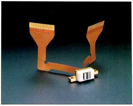
Technics fixed twin head for DCC, with flat, printed-circuit
cables for connection to record and playback circuits.
---------
Except for the new head block and DCC detection sensors, DCC transports can be much like those in analog cassette decks.
---------
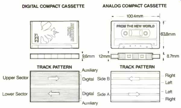
Fig. 1--Comparison of DCC and analog cassette shells and track patterns.
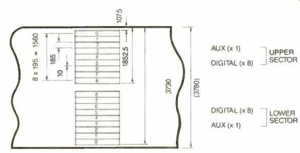
Fig. 2--Digital track layout of DCC. Dimensions are in microns.
Because DCCs can only be inserted in recorders and players one way, it is necessary that some form of auto-reverse mechanism be used in DCC machines. For bidirectional operation, two types of head configurations are possible. A turnover head, containing a nine-track upper section and a two track lower section, such as that shown at the right side of Fig. 4, could be mounted to a rotatable mechanism. Alternatively, a fixed twin head could be used, such as that illustrated at the left of Fig. 4. Such a twin-head arrangement has actually been developed by Technics and a photograph of the prototype head is shown. Details of the thin-film head construction of a single, rotatable head are shown in Fig. 5.
Besides the thin-film head, a DCC mechanism must provide for movement of the metal shutter and recognition of the ID holes of Digital Compact Cassettes. And, of course, it must also accept analog cassettes. It must be bidirectional and able to reverse tape direction in response to a command from a built-in microprocessor. Except for the new head block and the DCC detection sensors, tape transports used in DCC machines can be pretty much the same as those used in better quality analog cassette decks.
New DCC Functions
Besides the excellent sound quality that DCC will offer (more on that later), DCC offers several additional features not available with analog cassettes.
For example, in DCC, approximately 400 characters per second of text data can be retrieved during playback. This is more than enough to display the complete lyrics of songs and album notes, not to mention simple graphics.
Stored text data can be displayed on an LCD screen built right into the DCC recorder/player or on a TV screen, and several levels of data display are optional. The most basic level, which all prerecorded DCC tapes will include, has 12 characters by one line for display of album title and song titles. Depending on the tape, other levels could be 40 characters by two lines, or 40 characters by 21 lines for such information as performers, composers, history of the song or selection, or lyrics.
Table of contents (TOC) and other subcode information will allow for the same kind of access convenience found in CD and DAT machines.-A user will be able to program a DCC machine to play desired songs in any order. Direct access, repeat, music scan, and other familiar facilities can be easily implemented. Absolute-address and TOC data will allow DCC decks to find and access any desired position on the tape reliably and precisely. Of particular interest is the ability to record ID markers that will make the DCC machine automatically skip over undesired portions of the tape-a kind of soft editing. Similarly, a "home" marker can tell a DCC machine to rewind or reverse direction before it reaches the physical end of a tape.
How many of these convenience features will be implemented in DCC machines will, of course, depend on the manufacturer of the machine and its price category.
Table I illustrates the functional differences between prerecorded music tapes and home-recorded tapes. Notice that two levels of features will be available for home DCC recording, depending on the quality and cost level of the machine used. For the machines categorized as suitable for the "super user,” such table-of-contents features as track number, track time, and absolute time would be recordable and other TOC recording capability might be made optionally available. In simpler, less expensive DCC recorders, such recordable features would normally not be available.
As is true of all digital audio recording media, such as CD and DAT, the DCC standards will incorporate powerful error-correction capability. Of the total data rate of 768 kilobits per second of PASC-encoded audio information (assuming an original sampling rate of 48 kHz), fully 50% is devoted to redundant information that can be called on when error correction is required. The now-familiar Reed-Solomon error-correction scheme is used, and data is distributed amongst the eight data tracks in such a manner that large amounts of data can be lost to burst dropouts without affecting or altering musical reproduction quality during playback. Figure 6 illustrates just how much data can be missing. In fact, one entire track of the eight tracks used in the DCC system can be missing without affecting playback reproduction. If additional tracks are involved, the length of burst error it's possible to correct decreases as the number of tracks containing the error is increased. For example, as shown in Fig. 6, if the burst error involves as many as four track widths, full error correction can take place for a burst error lasting as long as 58 mS, corresponding to a tape length of 2.8 mm.
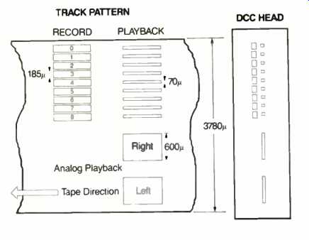
Fig. 3--Track layout for analog-compatible DCC head, showing both digital
record/play and analog gap widths and positions.
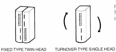
Fig. 4--Two DCC auto-reverse configurations.
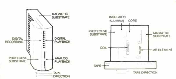
Fig. 5--Structure of single, turnover head for DCC record/play and analog
playback, showing front and top views.
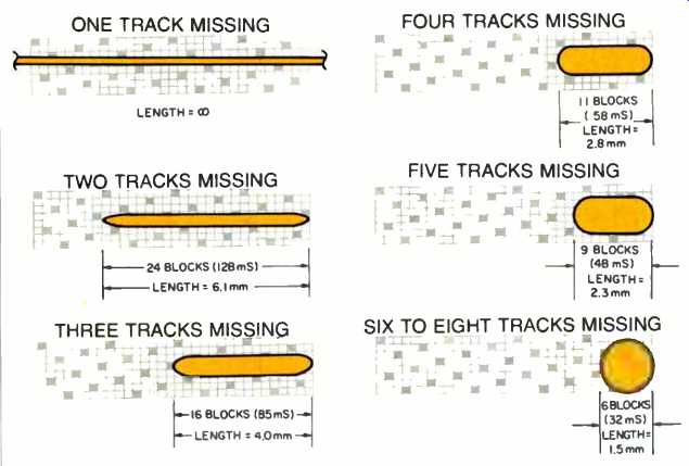
Fig. 6--How the length of a correctable DCC burst error varies with
the number of tracks affected. The area shown represents one ''frame" of
the recording (32 blocks, or 170 mS), covering a bit less than half the
tape area. The control track (not shown) would be above these tracks.
Shaded blocks contain parity information for error correction.
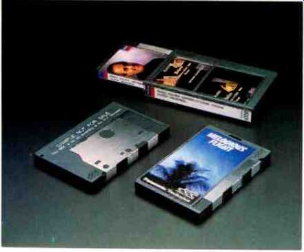
above: A DCC tape's "cover" is its flat, decorated top, visible through its slipcase (rear). A sliding corer protects the tape and hubs (left).
Objective Versus Subjective Evaluations of DCC
Because of the nature of DCC encoding and decoding, the usual single-tone tests of DCC recorders will not yield as meaningful results as would similar tests on linear digital systems.
As explained earlier, the PASC-encoding system assigns bits on a priority basis. Thus, if a single tone is recorded, for example, there will be enough bits in the bit pool to encode that tone in a fully linear manner, with no data reduction whatsoever. In fact, there would be ample bits left over during such a test recording. The same would hold true even if twin-tone intermodulation distortion testing were attempted. Accordingly, while such tests will no doubt continue to be performed by reviewers, including me, their significance will be considerably reduced.
The more meaningful evaluations of DCC recorders and recordings will re quire more subjective testing than objective, quantified testing.
Such subjective evaluations were, in fact, conducted during a recent visit by hi-fi writers to Technics headquarters in Osaka, Japan. There I listened to a wide variety of musical fare. Technics personnel had on hand a complete PASC encoder/decoder combination.
A switch enabled us to compare sound reproduced directly from CD sources versus the same musical material fed through the PASO encoding and decoding process in real time. Care was taken to add a short time delay to the direct, non-PASO, signal path, so both the direct and PASO signals would remain perfectly synchronized, but the switching between the direct and PASO encode/decode modes was not a "double blind" test. Most of the listeners at these sessions were experienced enough to judge sound quality without being prejudiced by knowing which sound source was which, even with the less-than-optimum room acoustics that existed. Several times, I detected a minimal difference in sound quality between the DCC equivalent (PASO encoded and decoded) version and the direct-from-CD version. There were also several musical selections during which I could detect no difference in sound quality between the PASC/DCC equivalent and the direct-from-CD sounds. In any case, I must emphasize that even those times when I did hear a difference, I could not honestly say which sounds were "better" or more faithful in musical terms.
I have no doubt that debates will abound once DCC hardware and software become available. I will say this about DCC even at this early stage, however: The sound quality I heard, as well as the dynamic range and signal-to-noise ratios inherent in music reproduced via DCC certainly surpassed what I've heard from even high-end cassette decks with Dolby B and C noise reduction. And after all, DCC is intended as an ultimate replacement for the analog cassette and not as a substitute for CD or, for that matter, DAT, which is likely to remain the recording medium of choice for professional applications and for audiophile purists who insist on nothing less than the ultimate.
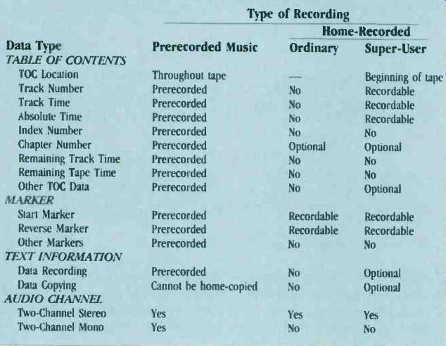
above: TABLE I--FUNCTIONS AVAILABLE ON EACH DCC RECORDING TYPE.
Interestingly, however, DCC standards make a provision for inputting signals that have 18-bit resolution.
Since CD and DAT standards limit signal resolution to 16 bits, it is even conceivable that at some time in the future we may actually encounter DCC recordings that sound noticeably and unarguably better than some CDs. It would be ironic if those audio purists who disparaged Compact Discs when they were first introduced would ultimately embrace a recording format that eliminates three-fourths of the data that would have been needed to capture all of the sound of an audio program in a traditional manner.
(Editor's Note: The line drawings in this article are courtesy of Technics.-E.P.)
(source: Audio magazine, Jan. 1992)
Also see:
Noteworthy: How PASC Data Compression Works In Philips Digital Compact Cassette (Sept. 1991)
New Life in Cassettes--Digital Duplications (Jul. 1991)
= = = =