Robert Carver [President and Director of Advanced Projects, Phase Linear Corp.]
THIS ARTICLE DISCUSSES some of the requirements modern high fidelity systems impose on the power amplifier. Renewed efforts to cope with previous shortcomings in power amplifier performance has led to a whole host of new technical problems and, necessarily, solutions. These problems, their recognition, their practical solutions, and their significance will be examined within the framework of existing power amplifier technology.
The author is an audiophile, a true-blue, dyed-in-the-wool high-fidelity enthusiast, lover of instruments and instrumentalities, lavishly scored orchestral showpieces, choruses and cathedrals. The sonic details of a single drum-roll can put me into a state of rapture that Timothy Leary himself would have envied. I have searched, like Sir Gallahad for the Holy Grail and T.R. Thompsont for the Lost Chord, for the low frequency pedal note that would leave the trolls of Ireland impotent. I have sought high frequency performance that would interest and please any passing bat. In short, I am a music lover for whom the quest for realistic reproduction of music has taken on a consuming devotion.
[*Actually, it was Adelaide Proctor. (Ed.)]
A look at the best of the available basic power amplifiers discloses that bandwidth, distortion, and noise figures extend far beyond the limits of audibility, and in some cases, even the limits of laboratory measurability. It might be concluded that power amplifiers have reached such levels of perfection that further advances could not possibly provide any audible improvements and would be simply "gilding the lily." In any event, it would seem, for example, that decreasing distortion from 0.5% to 0.05% or increasing the signal-to-noise ratio from 90 dB to 93 dB (twice as quiet) would not have any audible effect.
This conclusion might be justified because the deviations from perfection introduced by the rest of the signal processing chain (speakers, cartridges, and record surfaces) are several orders of magnitude greater than those introduced by the virtually perfect (by comparison) power amplifier. Further, it would seem reasonable to assume that two different amplifiers whose specifications in terms of power, distortion, frequency response, crosstalk, etc., are almost identical should be sonically indistinguishable from one another when compared in listening tests.
However, high fidelity enthusiasts have long observed that different amplifiers do, in fact, sound different and that some amplifiers seem to deliver a more robust low end along with sweeter, silkier highs. Yet their specifications, together with extensive laboratory testing and analysis can reveal no logical reason. A mystery. An engineer recognizes that a mystery is really only a lack of understanding born of insufficient data or the incomplete evaluation of existing data. In the case of the high fidelity power amplifier, it is simply that the human ear is capable of hearing and resolving on-going musical detail that has somehow eluded vast arsenals of laboratory test equipment.
Our own experiences are illustrated in the following experiments and examples. Extended listening comparisons have resulted in several interesting observations. First certain high quality transistor amplifiers "sounded better" by a small margin than high quality transistor amplifiers of identical power rating, in spite of the fact that the latter amplifiers had far "better" electrical specifications in terms of distortion, damping, bandwidth, etc. This difference in subjective sound quality was particularly dramatic when listening to high quality speaker systems using electrostatic components. Particularly, the high end was much airier and open, with much less apparent sibilance during high energy transients.
Let me digress a bit at this point and mention that particular care had been taken to eliminate the last vestige of crossover distortion in the inferior amplifier . At that point, we were virtually certain that crossover distortion was not the culprit. As shall be shown, this assumption proved to be valid.
The second observation was that two different high power, rather expensive transistor amplifiers introduced a mild "snapping" sound into the music when used with some acoustic suspension speaker systems. The "snapping" occurred primarily during low frequency high level passages and on some solo drum instrumentals. Interestingly, the snapping sound was not at all objectional during the drum solos--it tended to give each individual drum beat an added impulse and the illusion of tremendous transient response. However, on sustained low frequency notes, for example, the pedal notes of a pipe organ, the snapping was extremely annoying and clearly an indication of amplifier misbehavior.
In the third observation, in which a vacuum tube amplifier rated at 60 watts RMS per channel was compared with a transistor amplifier also rated at 60 watts RMS per channel, it was observed that the tube amp sounded somewhat more powerful. We discovered that we were able to increase the sound level significantly before objectionable distortion occurred when using the tube amp. In fact, the 60 watt/channel tube amp sounded the same, exactly the same, as a fine transistor amplifier rated at slightly over 100 watts/channel.
Two tube amplifiers were used, both vintage models, a Citation II and a Marantz Model 9. The transistor amp was of modern design and is very highly regarded.
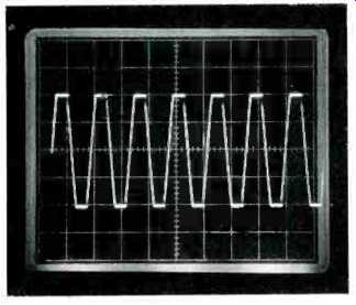
Fig. 1--Amplifier #1, a 60 W/chan. unit with regulated power supply, operating
into an 8 ohm load at clipping point, which 60 watts. Both channels operating.
When all of the transistor amplifiers included in our listening test were compared, an interesting pattern emerged, which was two-fold. First-relatively low power transistor amplifiers, those under 60 watts, and those built into receivers and integrated amplifiers, never exhibited any form of overt of obvious misbehavior. The only "fault" it was possible to render judgment against was their low power and consequent inability to produce satisfying music levels without severe overloading. On the other hand, two of the high power units exhibited the "snapping" phenomena and this we considered to be overt misbehavior and a grievous fault. (As we shall see later, the trouble was due to the protection circuits.)
The second part of the emerging pattern was that, given two transistor amplifiers of similar power ratings, it was found that units with a regulated power supply sounded the least powerful; that units with separate power supplies (two power transformers) sounded subjectively more powerful; and, interestingly, units with a single, common power supply sounded the most powerful.
Without exception, the units that appeared "most powerful" sounded significantly "cleaner" and more "open" when compared with the other units.
All amplifiers were operated at identical listening levels, and each was operating just below the point of audible overload using the "most powerful" sounding unit as the reference. All of these units had similar RMS power ratings. (As a matter of course, the a.c. power line voltage was adjusted slightly to give each amplifier identical continuous sine wave power output.) At this point, the task at hand is to identify the reasons for the subjective differences on a rigorous, scientific level, and approach the problems from an engineer's viewpoint.
The first investigation centered around determining why some amplifiers with identical power ratings did not subjectively sound equally powerful.
For our tests we used a commercially available 60 watt/channel amplifier with a regulated power supply and compared it with a unit specially built and designed for the experiment. It was designed to deliver 60 watts/channel with both channels in operation and it used a single unregulated power supply. An oscilloscope was installed across the speaker terminals and the test was arranged in the familiar A-B fashion. It was possible to switch from one amplifier to another instantly while simultaneously listening to music and observing the output of each amplifier on the 'scope.
It became immediately obvious why the second unit sounded more powerful. We observed that the second unit's output voltage would rise considerably higher prior to clipping than the unit with the regulated supply. It sounded more powerful because, in fact, it was more powerful when operated with music into a high fidelity speaker system.
To understand this, it is necessary to make a detailed examination of how the power supply of an amplifier effects the available output voltage swing.
The absolute value of the power supply voltage is what determines the maximum output voltage swing. If the power supply voltage is, for example, 63 volts, then the amplifier can deliver at its output terminals up to 63 volts peak to peak. Once current begins to flow, as the amplifier is delivering power to the load, internal losses cause this voltage to plummet downward. In the case of a 60 watt/channel amplifier whose power supply is unregulated, the supply must be able to maintain 63 volts under full load with both channels operating into 8 ohm load resistors. Since the supply is unregulated, and yet it must somehow supply 63 volts, it must necessarily be designed to deliver a substantially higher voltage during no-load or higher impedance load conditions in order to "make up difference" due to internal losses. In the case of a typical transistor amplifier, voltage losses in the power supply are approximately 30%. Hence the power supply voltage must be an unloaded 95 volts.
A regulated power supply can be thought of as "loss free" because its output voltage remains constant and does not vary from a no-load condition to a full load condition. In the case of the 60 watt/channel amplifier, it is regulated to 63 volts-never higher, never lower.
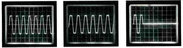
Fig. 2--Amplifier #2, a 60 W/chan. unit with dual power supply. The clipping
point is the same as Fig. 1, 60 watts, both channels operating.
Fig. 3--Amplifiers #3, a 60 W/chan. unit with a single power supply. The clipping point is also 60 watts, both channels operating.
Fig. 4--Amplifier #1 with low frequency tone burst simulating drum beat. Clipping occurs at 60 watts. The load is an 8 ohm acoustic suspension loudspeaker.
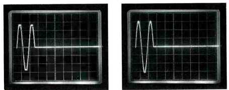
Fig. 5-Amplifier #2, with the same tone burst and speaker load, delivers
about 20% more voltage than amp #1 under dynamic music conditions. Clipping
is just under 90 watts.
Fig. 6-Amplifier #3, with the same tone burst and speaker load, delivers about 30% more voltage than amp #1 under dynamic music conditions. Clipping is over 100 watts.
Never higher, never lower. Therein lies the reason that the amplifier with the unregulated supply sounds more powerful. Speaker systems are not of constant impedance; they vary over a wide range, from below 8 ohms and climbing to a high of 30 ohms or more.
At resonance, the speaker impedance is at a maximum and if substantial power is to be delivered, the amplifier must have substantial output voltage capabilities. The expression for power is P = V2/R. From this it is readily seen that if the impedance R increases, the voltage must increase or the power delivered will decrease. If the power supply is regulated, it cannot increase, and the available power under dynamic conditions is severely curtailed.
Oscilloscope photographs in Figs. 1 through 6 graphically illustrate these effects. Referring to Fig. 1, the 60 watt/ channel amplifier with the regulated supply is being driven to the clipping point (point of overload) with a continuous sine wave signal. Both channels are operating. Only one channel is shown in the photo. In Fig. 2, the unit with two power transformers in its power supply is being similarly driven to the clip point. Fig. 3 shows the amplifier with the unregulated power supply similarly driven. Notice that the clip point is the same for all three units, 63 volts peak to peak. In Figs. 4, 5 and 6, a low frequency tone burst is used to simulate a drum beat. The load is an eight ohm acoustic suspension loudspeaker. The unit with the regulated supply (Fig. 4) clips at its previous voltage level, 63 volts. However, the units with the unregulated supplies Figs. 5 and 6 are able to deliver a higher voltage prior to clipping. The unit with the single unregulated power supply is clipping at a voltage level approximately 30% higher than its sine wave continuous clipping level. Thirty percent is almost a 1/3 increase, and since power is proportional to the square of the voltage, the power increase is approximately 1.3 x 1.3 = 1.69. Almost seven tenths more effective power is available from this amplifier.
From another point of view, for any given average power level, the second amplifier will be clipping significantly less during musical peaks, and is thereby generating significantly less distortion. This is why the second amplifier sounded "sweeter and airier." We repeated these experiments with our vacuum tube amplifier and compared results. It turned out that the tube unit behaved in a manner similar to the amplifier with the unregulated supply, with an interesting exception.
When the tube amplifier was very lightly loaded, with a load of around 30 ohms or higher, its voltage swing could go extremely high, producing almost 50% more than the fully loaded condition. This high impedance load is the load condition that an electrostatic midrange or tweeter unit imposes on an amplifier. The power demands are rather moderate because the load impedance under dynamic conditions is relatively high, and therefore the voltage requirements of the electrostatic screens are high. Present day electrostatic mid- and high-range screens require their power at high voltage levels, precisely where a vacuum tube amplifier excels.
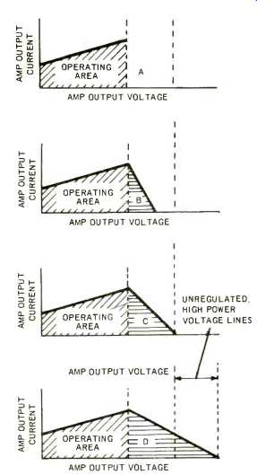
Fig. 7--Why four different amplifiers, each rated at 60 watts/channel sound
subjectively different. A, this area is forbidden because of the tight power
supply regulation. B, This area is available to an amplifier with dual power
supplies. C, This area is available an amp with an unregulated power supply.
D, This area is available to an amplifier with an "idealized" design.
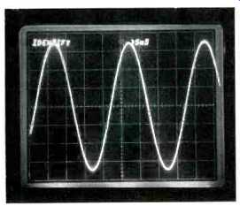
Fig. 8--Output of a high power amplifier operating at 40 Hz into an 8 ohm
resistive load. Power level is 150 watts.
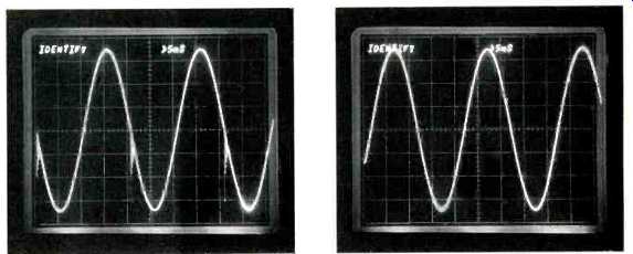
Fig. 9--The same amplifier as Fig. 8 operating at 40 Hz into an 8 ohm loudspeaker
load. The tearing at the center of the waveform is due to false triggering
of the protective circuits. The power level is again 150 watts.
Fig. 10--The same amplifier as in Figs. 8 and 9 with the same loudspeaker as Fig. 9, but with the amplifier's protection circuits removed. Note the perfect waveform.
These findings are summarized in graph form in Fig. 7. Notice that the "best sounding" amplifier (7C) has available additional operating area that is "forbidden" by the amplifier with the regulated power supply (7A). Figure 7B shows the operating area of an amplifier with two power transformers, and Fig. 7D depicts a 60 watt amplifier idealized to represent a "Perfect" 60 watt/channel amplifier. Notice that the available operating area is almost double that of the unit with the regulated supply. The "perfect" 60 watt/ channel amplifier would have, as a design goal, a very high voltage power supply. It would sound very clean and very powerful. The high voltage design approach produces the very best possible "sounding" amplifier, but, as is often the case, there is a tradeoff against other desirable characteristics.
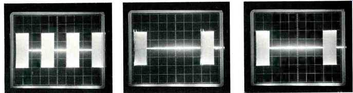
Fig. 11--A 15 KHz tone burst output of a high power amplifier into an 8
ohm inductive (loudspeaker) load. Note the perfect response.
Fig. 12--The same 15 KHz tone burst with the repetition rate set for 500 Hz. Note the limiting and distortion on the leading edge of each burst. This is caused by the protection circuits confusion of the simultaneous low repetition rate and high burst frequency with an overload.
Fig. 13--Same conditions as in Fig. 12, except that the protection circuits have been disconnected.
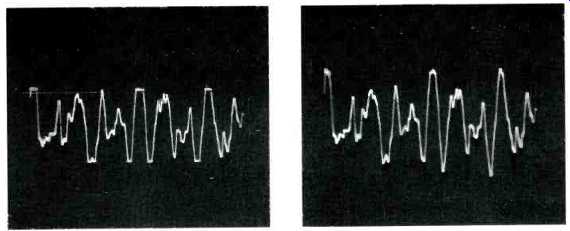
Fig. 14--Instantaneous single sweep photo of an opening piano allegro. Note
the flattening that is occurring near the peaks as the amplifier overloads.
The average power is about 38 watts. The amplifier is a 120 W/chan. unit.
Fig. 15--Same type of photo as in Fig. 14, but the amplifier is a 350 W/chan. unit. Note that the peaks are not clipped.
The liability assumed with the high voltage amplifier is that the normal operating temperature of the amplifier must be higher than with the conventional design. If the designer is willing to accept this drawback and is willing to design into his unit an extra margin of thermal stability, an amplifier using this approach would be without peer.
A detailed examination of high powered amplifiers in the 100 to 150 watt/ channel range reveals shortcomings and problems unique to these units.
A severe design problem that must be undertaken when building a high power amplifier is to design an adequate protection device for the unit. All high power amplifiers must incorporate some form of protection circuit to prevent their destruction in the event of an accidental overload. The protection circuit must limit the output of an amplifier if it is operated into an improper load, but it must not in any way limit the output of the amplifier when operated into a proper, normal, or loudspeaker load. These two conditions represent conflicting requirements imposed on a protection circuit, and it shall be shown that in many instances these conflicting requirements have resulted in protection circuits that do not completely protect the amplifier, or worse, often limit the output in some manner that results in an audible degradation of the musical signal. In the most severe cases, outright amplifier misbehavior results.
Fig. 8 is a 40 Hz output signal delivered into an 8 ohm resistive load.
The power level is 150 watts. Note that the signal is perfect. Fig. 9 is the same amplifier operated into a complex load whose impedance is also 8 ohms.
The load is an 8 ohm acoustic suspension loudspeaker. Notice the large spikes that are occurring on the downward slope of the sine wave. These spikes are caused by false trigger action of the protective circuitry built into the amplifier and cause the "snapping" sound mentioned previously. The spikes are called "flyback" pulses and are generated as follows. As the sine wave reaches its peak value and begins to decrease, the energy that has been stored in the magnetic field associated with the inductive component of the loudspeaker impedance is forced to flow back into the amplifier. The protective circuit senses this reverse energy flow as an overload and commands the amplifier output stage to shut down. This happens instantly, and when the output stage turns off, the energy is prevented from flowing back into the amplifier.
The result is a large voltage spike due to the collapsing magnetic field in the loudspeaker. An easily understood analogy is an automobile spark coil and a set of points. When the points interrupt the flow of current, the collapsing magnetic field inside the coil generates a high energy spark. In an analogous manner, the voltage at the loudspeaker terminals rises until clamping diodes (built into all large amplifier output stages) conduct and prevent any further increase. The audible effect is the "snapping" misbehavior and occurs during heavy low frequency demands. Fig. 10 is the same amplifier but with the protection circuits disconnected and operated into the loudspeaker load. Observe that the sine wave is again perfect.
Figures 11, 12 and 13 show the output of an amplifier rated at over 100 watts operated into a loudspeaker system. In Fig. 11, the signal consists of a 15 kHz tone burst whose ON and OFF times are equal. Observe that the amplifier output response is perfect.
Fig. 12 consists of the same 15 kHz tone burst but with the following characteristics. The OFF time is very long compared to the ON time. The repetition rate of the tone burst is very low. In this instance, 500 Hz. This particular tone burst simulates the simultaneous output of a low frequency musical note (the repetition rate) and a high frequency musical note (the internal tone burst frequency). This would, in a musical sense, correspond to the simultaneous reproduction of a low frequency woodwind note and, say, a harp. Notice that the first few cycles of the tone burst are limited and distorted. This is because the protection circuits in the amplifier confuse the simultaneous low and high frequencies with an overload, falsely trigger, and limit the amplifier output. It is only under certain combinations of simultaneous low and high frequency demands that the protection circuits are falsely triggered into operation. Fig. 13 shows the same output as Fig. 12, but with the protection circuits removed. Again, note that the response is perfect.
The audible effect of this particular amplifier misbehavior is much more subtle than the previous example. The effects range from a slight "edginess" and "stridency" to outright breakup associated with the highs. As Mr. C.G. McProud put it, "It's when an opera singer hits her high C at the end of an aria." A general review of all of these photographs graphically indicates the need for improvement in current power amplifier performance. These shortcomings served to solidify the goals and objectives an amplifier design should reach.
A perfect amplifier should be powerful enough never to overload, even during low frequency passages and on musical peaks. The protection circuits should never falsely trip and generate high distortion or amplifier misbehavior, yet they should safeguard the amplifier in the event of an accidental short circuit or from any other form of abuse.
An amplifier must have a mechanism to protect the loudspeaker from accidently dropped tonearms or amplifier failures, and all of these qualities must be built in.
How powerful? This question has been asked and answered more often and in more ways than is easily imagined. Simply stated, an amplifier should be powerful enough to prevent overload and clipping when operated at a satisfying listening level. Instant overload recovery is not enough.
The best speaker systems today obtain their smooth, wide range low distortion performance by significantly sacrificing efficiency. That's simple physics. The best are incredibly good, but they require large peak power and output voltage capability of an amplifier. Figure 14 shows a 120 watt amplifier reproducing the opening allegro piano note from Part III, of Beethoven's Emperor concerto performed by Rudolf Serkin. The volume level has been adjusted so the piano volume level approximates a live piano. The speaker system is a modern unit which employs active equalization. Observe that piano note peaks are being clipped.
This leads to harshness and may cause listening fatigue. Figure 15 is the same passage but with a 350 watt amplifier.
Note that clipping does not occur. The sound is smooth, sweet, and open. The subjective volume level is identical in both cases. The average power level in both cases is approximately 38 watts.
If the goal is to eliminate the severe amplifier distortion that occurs on musical peaks and during low frequency passages, and if the best wide range speakers available today are utilized, a minimum of 200 watts/channel is required. A maximum of over 500 watts/channel is required when using some of the very latest, highly inefficient speakers. The important point to remember when dealing with these high power levels is that the peak to average power ratio of musical material is approximately 10:1. This means that when a 200 watt/channel amplifier is operating full tilt into a set of loudspeakers, the long time average power delivered to the loudspeaker is only 20 watts. In addition, these loudspeakers are designed to safely sustain extremely high impulsive power levels. For example, the new Acoustic Research LST loudspeaker system can safely sustain 1000 watts for brief time periods. It is this capability that will allow a high level drum beat, a low frequency pedal note, or an opera singer hitting her high C at the end of an aria to be safely accommodated by the loudspeaker system.
The first step in designing a 700 watt amplifier was to evaluate existing design approaches to high power. Primarily, the problem is one of obtaining the required high output voltage. Three hundred fifty watts @ eight ohms, two channels, requires an unregulated power supply capability of over 200 volts. Until very recently, the very best existing transistors had sustaining voltages of only 120 volts, and, at that, a designer was pushing the state of the art to build an amplifier with a 120 volt supply (150 watts). The standard solution to higher voltages is to use low voltage transistors and use a step-up transformer or auto transformer at the output of the amplifier. The disadvantages of this approach are many. Excessive phase shifts through the transformer generate stability problems, increase distortion, reduce the bandwidth, and transformers are excessively heavy and expensive.
We computed that an amplifier using step-up transformers or auto-transformers would weigh over 130 pounds! A second design approach consists of connecting two or several low power amplifiers together in series to obtain the required high output voltage. Amplifiers connected in this fashion are said to be "in bridge" and their separate output voltages add together or double.
Since power increases as the square of the output voltage, doubling the voltage would quadruple the power. For example, two 150 watt units in bridge would yield four times 150 or 600 watts.
This design approach is a fairly workable one, but it too suffers severe and fundamental drawbacks. The input and the output grounds are not common.
Rather, they are "floating" above chassis ground and any attempt to use such an amplifier in a multiple unit installation would raise havoc with the grounding system. Another drawback is that a stereo amplifier would require four separate amplifiers connected internally to obtain two channels; this plus the required double power supply would even further add to the complexity, weight, and cost.
Solving the primary problem of transistor voltage breakdown required close work with a major transistor manufacturer. The basic power transistor used in the 700 watt amplifier design is a 600 volt television horizontal sweep transistor. This basic power transistor was modified extensively in order to obtain the best suitability for high power amplifier application. Energy breakdown levels, current gain, pulse safe operating area, and other transistor parameters were carefully adjusted in order to optimize their use.
Another of the many problems associated with transistor amplifier design is the problem of crossover or "notch" distortion. Historically, this was a severe drawback in early transistor amplifiers. It was successfully solved by allowing the output transistors to operate in a mode which was somewhat less efficient than ideal and represented one of many engineering compromises. In order to eliminate crossover distortion, it was necessary to allow a small amount of idling current to flow at all times.
This idling current would generate a small amount of heat but was perfectly acceptable for small, low voltage amplifiers that had at most two pair of output transistors. For a large 700 watt amplifier, the amount of heat that would be generated by idling current flowing in 24 output transistors would be excessive. It was necessary to incorporate a novel biasing circuit that would allow the output stages to operate without idling current (pure class B) and to simultaneously completely eliminate crossover distortion. This biasing circuit is used in integrated circuit "op-amps" but had previously never applied to power amplifiers. The success of this approach depends on the careful attention to specific power transistor parameters in the low current region. Crossover distortion appears as high intermodulation distortion at low levels. The best transistor amplifiers have attained IM figures of well below 0.05%. Production 700's attain IM figures at 750 milliwatts of between 0.01% and 0.02%. Speaker protection is accomplished by a "crow bar" circuit in which heavy fault-current (for example, caused by accidently dropping a tone arm, or an output transistor failure) is forced to flow through a pair of fuses rather than through the loudspeaker. Since the "crow bar" forces heavy fault-current to flow through the fuses and not through the loudspeaker, they open immediately and prevent any possibility of damage.
The problem of amplifier misbehavior caused by false triggering of the protective circuits was solved by incorporating a totally new protection circuit design which monitors, from microsecond to microsecond, the energy* that is being absorbed by the output transistors during normal operation. All previous protection circuits have monitored the current, or in the case of large amplifiers, the power. The energy limiting approach results in an amplifier that can provide approximately three times as much power as an amplifier equipped with current limiting or power limiting circuits.
Whenever a loudspeaker engineer makes an attempt to extend or smooth the frequency response of his design, or to lower the distortion, the laws of physics demand that the loudspeaker become ever less efficient.
These two facts of life, the conflicting requirements of sonic perfection versus loudspeaker efficiency has always set an upper practical limit on loudspeaker performance. The recent availability of truly high power amplifiers has allowed speaker designers a new freedom, and without question, the best speaker systems of tomorrow will be capable of truly awesome performance.
'Energy is the time integral of power. Expressed mathematically, Energy, E = VI dt, where V = Voltage, I = current, and with the limits of integration chosen to be over one half cycle of the waveform.
(Audio magazine, Feb. 1972)
Also see:
Amplifiers--A look at requirements and specifications (Apr. 1971)
Fail-Safe Audio Amplifier Design (Feb. 1973)
Buying Watts and Other Things (Feb. 1973)
Intermodulation Distortion: A Powerful Tool for Evaluating Modern Audio Amplifiers (Feb. 1972)
Transient IM Distortion in Power Amplifiers (Feb. 1975)
FTC Power Ratings: An Optimistic View (Feb. 1975)
= = = =