MANUFACTURER'S SPECIFICATIONS
FM Section:
IHF Sensitivity: 2.0 uV or better. S/N Mono: 68 dB; Stereo: 66 dB. THD, Mono: 0.3%; Stereo: 0.4%. IF Rejection: 100 dB. Image Rejection: 70 dB. Selectivity (Carrier down): 68 dB. Spurious response: 100 dB. Capture Ratio: 1.8 dB. Muting Threshold: 10 uV. Stereo Separation: 35 dB at 1 kHz. 38 kHz suppression: 50 dB. SCA Suppression: 74 dB.
AM Section:
IHF Sensitivity: 50 uV (external antenna). Selectivity: 42 dB. IF Rejection: 40 dB. Image Rejection: 40 dB. THD (30% Modulation): 0.5%.
Amplifier Section:
Power Output: 40 watts per channel, 8-ohms; 52 watts per channel 4-ohms, continuous power, both channels driven, 1 kHz input. 38 watts per channel, continuous power, 8 ohm loads, both channels driven, at any frequency from 20 Hz to 20,000 Hz. Power Bandwidth: 7 Hz to 30,000 Hz. THD: 0.2% at rated output. IM Distortion: 0.2% at rated output.
Damping Factor: 48 (at 8 ohms, 1 kHz). Frequency Response: 12 Hz to 70,000 Hz, -1.5 dB. Input Sensitivity: Phono: 2-8 mV, adjustable; Tape 1, Tape 2: 130-250 mV, adjustable. S/N, Phono: 68 dB referred to 4 mV input signal: Tape 1, 2 82 dB referred to 260 mV input signal.
Preamplifier output: 900 mV. Recording output: 800 mV. 800 mV.
Dimensions: 17" w. x 4 3/4" h. x 12 3/4" d. (including knobs)
Weight: 20 lbs.
Retail Price: $429.90.
Remember when the people from Tandberg startled the audio industry by proving that a reel-to-reel tape recorder could deliver full frequency response and true high fidelity at a speed of 3 3/4 inches-per-second? No tricks were involved, just careful engineering, precision assembly and good quality control that set the standard for other manufacturers of tape products to follow for years afterward. Well, to quote from a recent Tandberg advertisement. ". . . the guys who brought you the world's best tape recorders" now bring you an outstandingly designed receiver-their first entry in the purely electronic component category of components.
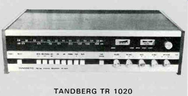
The Tandberg TR-1020 is not really that much smaller, trimmer and lower-profiled than competitive products in the same power output range--it just looks that way, thanks to an outstanding job of styling and human engineering done by Tandberg's engineers. With power off, the front panel looks like three floating strips of anodized aluminum. Nomenclature is clearly printed in black and--wonder of wonder--sit's large enough to read without squinting. The upper portion of the panel, blacked out until power is applied, contains a well illuminated FM and AM dial scale whose illuminated red pointer segment is illuminated only when FM or AM operation is selected. To the right are two meters, a signal strength meter operative in both AM and FM service and a center-of-channel meter for FM tuning. The tuning knob is located at the extreme upper right and is coupled effectively to a heavy flywheel. Major operating controls are all neatly arranged in a single row below the dial area and include ten push-push buttons for such functions as on/off, FM muting, AFC, FM, AM, PHONO, Tape 1, Tape 2 and Tape Monitor.
Rotary controls include a master volume control, balance control, dual concentric clutch operated bass and treble controls and a speaker selector switch with positions for main, remote and main plus remote operation of speakers as well as an off position for headphone listening. The left end of this row contains the usual stereo headphone jack while, at the extreme right there is a phone jack labeled "Tape 3", about which we shall have more to say presently.

Fig 1--View of rear panel.
If you didn't read the instruction booklet, you'd think that the controls just named would be all that are available, until you pull down on the lower aluminum bar which is actually a hinged door that discloses eight more pushbuttons. These offer Stereo, Mono Left, Mono Right. Loudness, Low Filter, High Filter (two kinds) and Preamp record. All but the last are self-explanatory and make for a most flexible control center, but that last button fills a very real need that many of us have been aware of for some time. When that button is depressed, all the control facilities such as tone controls, filters, loudness and the like are inserted ahead of the tape 3 output jack referred to earlier. Thus, the serious recordist can brighten, filter, boost or otherwise rebalance an old recording that he or she is trying to transcribe onto tape. What a simple but clever idea!
The real panel, shown in Fig. 1, contains eight screw-terminals for making speaker connections for two pairs of stereo systems. Each pair of terminals also has, located between
them, a polarized receptacle for "plugging in" speakers without having to re-wrap wire leads every time speakers are disconnected. The model we tested did not come equipped with the appropriate plugs, however, so we could not try out this feature and had to resort to conventional wire-wrapping of speaker leads. At the extreme left of the panel are a pair of preamplifier-main amplifier jumpers which can be removed if you want to use the preamplifier and power amplifier sections separately. Phono inputs as well as inputs and outputs for Tape 1 and Tape 2 are located along the lower edge of the rear panel, as are a switched and unswitched convenience ac receptacle and receptacles for antenna connection. Two plugs were provided for this latter receptacle, each coded differently so that the FM antenna cannot be inadvertently connected to the am receptacle holes and vice versa. The plugs do not involve soldering, and only a small screwdriver is needed to connect the transmission line from either an FM or external AM antenna to the appropriate plug. There is also a receptacle which will accept a 75-ohm coaxial cable connector. A thumbscrew terminal for system ground completes the back layout.
Three more controls are located on the bottom of the receiver. These are input sensitivity controls for phono, tape 1 and tape 2 inputs, enabling you to balance levels when switching from one program source to another or from self contained AM and FM to one of the external program sources. This refinement is hardly ever found on all-in-one receivers and it, like so many of the other features found in the TR-1020, is most welcome.
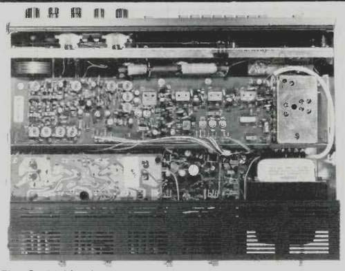
Fig 2--Inside view
Figure 2 shows the inside of the chassis, with the included walnut cabinetry removed. The "cabinet", by the way, is one of the cleverest enclosures we've seen yet. It really consists of two side wood panels and an interlocking top' panel. To service the instrument, only four side screws need be removed and all panels slide apart, yet, when fully assembled, the enclosure looks and feels like a beautifully crafted piece of furniture. Internal layout of the TR-1020 is superb, for while an enormous amount of electronics has been crammed into a relatively small cubic volume, circuit boards are arranged so that almost every part is accessible without having to disassemble the entire receiver. Circuit features include an FET mixer in the AM section, dual-gate MOS-FET's used for both RF and mixer stages in the FM front end which is electronically tuned (there is no variable capacitor-only varactor diodes), multi-pole FM-IF filters and a well designed stereo multiplex circuit with positive, automatic switching from mono to stereo. The power amplifier section employs a true complementary symmetry circuit and utilizes two separate power supplies-one for each amplifier channel for minimum interaction between channels.
Electrical Measurements
One of the characteristics that sets apart a really exceptional FM tuner section from the run-of-the-mill variety is the steepness with which it begins to reject background noise as signal strength is increased. The Tandberg TR-1020 is unexcelled in this respect, as can be seen in the curves of Fig. 4. With only 3 microvolts applied, S/N already reached a very usable figure of 51 dB. At IO microvolts, S/N was over 65 dB-and, more important, the figure was the same for mono and stereo. Ultimate THD in mono reached a low of 0.2%, as claimed and, again, that low distortion was reached with barely more than 10 microvolts of signal applied. Ultimate S/N ratio reached 70 dB in mono operation (higher than claimed) and 67 dB in stereo. Aside from these impressive numbers, that means that relative to 100% modulation both the residual 19 kHz pilot and the residual 38 kHz component are at least "down" 67 dB or more, otherwise they would have contributed to our reading.
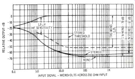
Fig 3--FM performance
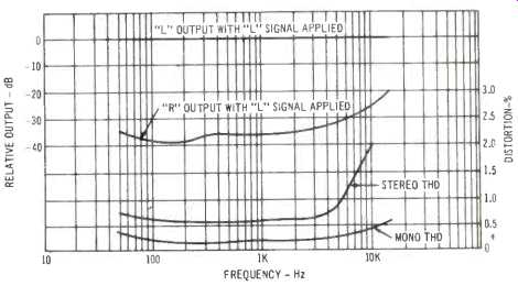
Fig. 4-Separation, stereo and mono distortion.
Mono and stereo THD were plotted for all usable audio frequencies in Fig. 4. Mono THD remains at about 0.2% for all frequencies between 100 Hz and 5 kHz, reaching maximums of 0.4% and 0.6% at frequencies of 50 Hz and 15 kHz respectively. Stereo THD is equally impressive at 0.6%, though this reading came out a bit higher than claimed by Tandberg. The rising THD at higher frequencies in stereo is caused by "beats" rather than by actual harmonic distortion and should therefore not be regarded as a serious or audible problem. We have been including this data in recent reports primarily to show how various manufacturers fare in this regard. A 2% "beat", as read at 10 kHz, is actually a very low order of this phenomenon--about the lowest we have read for any receiver tested in this way.
Stereo separation met published claims, with separation decreasing from its mid-band value of 36 dB to 33 dB at 50 Hz and 25 dB at 10 kHz.
If you re-read the manufacturer's published specifications with regard to amplifier output power you will note that Tandberg is about as thorough and conservative in its power statements as anyone could be. If all manufacturers stated this many facts about their power output capability in a given product the confusion which prevails would soon disappear.
As a matter of fact, however, the TR-1020 does considerably better than is claimed for it. For example, we measured 0.2% THD with 45 watts per channel output driving 8-ohm loads simultaneously in both channels-this against the 40 watts per channel claimed. If you prefer to rate the THD for maximum power output at 0.5%, then the amplifiers will each produce 50 watts per channel under the same load and driving conditions. At all power levels below 30 watts per channel, we found that we were reading the residual THD of our own signal source, which we know to be about 0.04%. There was absolutely no evidence of rising THD at low power levels--usually associated with cross-over distortion in class "B" circuits. IM distortion, shown in Fig. 5 along with the few THD measurements that we could significantly portray, was also well below our test equipment "limits" and reached its rated 0.2% at 45 watts of output per channel, as opposed to the 40 watts claimed by Tandberg.
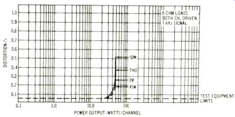
Fig 5--THD and IM characteristics.
A plot of frequency versus THD at power levels of 1 watt, 20 watts (half rated power) and 40 watts is shown in Fig. 6.
Again, for all but the very lowest frequencies we were limited by our test equipment, indicating that at frequencies above or so, THD at all power levels tested was below 0.04%! Even at 20 Hz, we were able to obtain 40 watts per channel from both channels driven simultaneously at a THD of 0.5%. Power bandwidth, shown in Fig. 7, extended from 5 Hz to 50 kHz, a good deal wider than claimed. The curve is referenced to 40 watts output at 0.5% THD. If one backs off on the THD to Tandberg's 0.2% reference, power bandwidth still extends from 7 Hz to 35 kHz, a bit better than claimed.
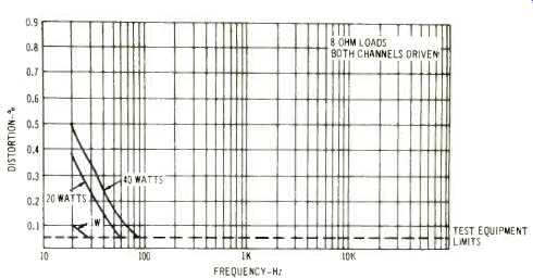
Fig. 6--THD vs frequency.
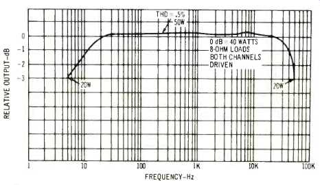
Fig. 7--Power bandwidth
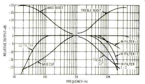
Fig. 8--Tone control and filter curves
Figure 8 graphically shows the tone control action and filter response of the TR1020. The low frequency filter has a slope of 12 dB per octave, making it highly effective in reducing rumble. The two high-frequency filters may be used singly or together, to produce the roll-off characteristics shown in the curves.
Listening Tests
I am convinced that part of the joy of operating a well designed receiver is in the use of its control and switching features. It's often hard to separate actual sonic performance from front panel flexibility. The Tandberg TR-1020 excels in both areas. While we normally read operating manuals carefully when evaluating a new piece of equipment, we must confess that one marvelous feature of this receiver escaped us until we started to listen to the unit. In the course of moving the speaker selector switch to its A+B position (we were trying out twin pairs of speakers to judge power adequacy), we inadvertently pulled on the speaker-switch knob.
Suddenly, the "signal strength" meter began to move in correspondence to the audio program we were listening to.
Sure enough, it's supposed to! When this switch is pulled outward, that meter becomes a power output meter, offering precise readings which can be correlated with actual power reaching your speakers. A calibration chart is provided in the instruction manual for 4, 8 or 16 ohm 'loads and the meter, which is peak reading, reads the highest power supplied by either channel at any given instant.
In the course of listening to FM, we found the muting circuit to be highly effective and "pop" free. If we may make a suggestion, however, it is our feeling that 10 microvolts is too high a setting for the mute threshold-5 microvolts would enable us to receive more perfectly noise-free stations and still take advantage of interstation tuning silence, thanks to the remarkable quieting capability and limiting characteristics of the tuner section of this receiver. Of course, this is a relatively minor point, since the muting circuitry can be disabled altogether if desired. With muting off, we picked up no fewer than 52 listenable signals, of which 24 were received in stereo. Normally, with this many stations received in our area we should have picked up more stereo signals, however noisily. The TR-1020, however, has its stereo switching threshold set at 10 microvolts as well, so that some of the stations we heard were really broadcasting in stereo, but at signal strength which we received they would have been too noisy for satisfactory stereo enjoyment. In this case we are in perfect agreement with Tandberg's settings of this circuit.
Amplifier sound is superb at every listening level, but we were particularly impressed at how transparent and clean the sound seemed to be at very low, background listening levels.
This, by the way, is a good way to test overall amplifier performance since it often shows up flaws that would be masked at higher listening levels. In this case there were no such flaws. Because there is plenty of power to spare--even with our low-efficiency speaker systems, we were able to turn up phono level for really big sound and in doing so we fully appreciated the more than 65 dB of dynamic range made possible by the TR-1020's low, low noise and hum level which was still all but inaudible at the loud levels at which we set the controls.
We did some experimenting with the "preamp controlled" Tape 3 output described earlier. We purposely played one of our "1954 vintage" operatic LP records which, while still remarkably free of surface noise (it's a performance of Boheme that we don't particularly care for artistically and so it hasn't been played to death), was notably lacking in high frequency response. By juggling the treble controls and the high frequency filter, we were able to produce a tape recording of this relic that actually sounds better than the disc in terms of overall balance. Let's see you try that without having a studio console replete with professional equalizers, filters and a host of other signal processing devices! If the Tandberg TR-1020 sold for around $600.00 we'd say it was competitive with other receivers in that price class and still has a few features going for it that other $600 units omit. At under $430.00, it's a bargain. The "guys from Tandberg" have, indeed, done it again!
-Len Feldman
(Adapted from: Audio magazine, Feb 1973)
Also see:
Tandberg Model TR-2075 Stereo AM/FM Receiver (Equip. Profile, Mar. 1976)
Tandberg 3080A FM Receiver (Equip. Profile, July 1989)
Tandberg Compact Disc Player (Nov. 1987)
Tandberg TCA 3018A Preamp and TPA 3026A Amp (Apr. 1987)
Tandberg 3008A Preamp and 3009A Amp (Jan. 1986)
= = = =