MANUFACTURER'S SPECIFICATIONS
FM Tuner Section
IHF Sensitivity: Mono, 1.8 µV (10.3 dBf).
50-dB Quieting: Mono, 3µV (14.8 dBf); Stereo, 40µV (37.3 dBf).
S/N: Mono, 78 dB; Stereo, 75 dB.
Muting Threshold: 6µV (20.8 dBf).
Stereo Threshold: 15 µV (28.8 dBf).
THD at 50-dB quieting: 0.3%
THD at 65 dBf: Mono, 0.2%, Stereo, 0.3%.
Capture Ratio: 0.9 dB.
Selectivity: Alternate channel, 80 dB; Adjacent channel, 10 dB.
Spurious Rejection: Better than 95 dB.
I.F. Rejection: Better than 95 dB.
Image Rejection: 70 dB.
AM Suppression: 70 dB.
Frequency Response: 30 Hz to 15,000 Hz, +1,-2 dB.
Stereo Separation: 40 dB from 60 Hz to 10 kHz.
Sub-carrier Rejection: 60 dB.
AM Section
IHF Sensitivity: 20 µV, external antenna; 250 µV/M, internal antenna. Selectivity: 45 dB. I.F. Rejection: 80 dB. Image Rejection: 90 dB. THD: 0.8% re: 30% modulation.
Amplifier and Preamplifier Section
Power Output: 75 watts continuous power per channel, 20 Hz to 20 kHz, 8 ohm loads (100 watts at 4 ohms). THD: No more than 0.15% (0.2% for 4 ohm power rating). IM Distortion: Less than 0.15%. Damping Factor: 60 at 8 ohms.
Overall Frequency Response: 6 to 80,000 Hz,-1.5 dB. S/N: Phono 1 re: 4.4 mV input, 70 dB; Phono 2 re: 3 mV input, 68 dB; Tape 1 and 2, 82 dB.
Input Sensitivity: Tape 1 and 2, 150 to 600 mV; Phono 1, 2.2 to 10 mV; Phono 2, 3 mV.
Maximum Phono Input at 1 kHz: Phono 1, 150 mV; Phono 2, 50 mV. Bass Control Range: ±15 dB e 50 Hz. Treble Control Range: ±15 dB @ 10 kHz. Mid-Range Control Range: ±7 dB @ 1 kHz. Low Filter:-3 dB at 70 Hz, 12 dB/octave. High Filter 1: -3 dB @ 8 kHz, 12dB/octave. High Filter 2: -3 dB @ 8 kHz, 6 d B/octave.
General Specifications
Dimensions: 20-1/8 in. W x 6 in. H x 13-7/8 in. D.
Weight: 27.1 lbs.
Price: $1,100.00.
Before even considering the features and performance of Tandberg's most powerful and most complete receiver, we'd like to comment on the fact that this is the first receiver we've tested that is accompanied by fully spelled out FM specifications, listed in accordance with the newly approved IHF/IEEE FM Measurements Standards issued in mid-1975.
Besides being a "first" for that well-respected Scandinavian company, it tends to tell us something about their design philosophy and marketing approach: Tandberg is proud of its products and has nothing to hide. Those familiar with Tandberg's earlier receiver efforts will note that this time the low, sleek front panel format has been retained, but without the hinged door which covered less-often used controls on the less powerful models. Tandberg evidently felt that they wanted prospective customers to see all the flexibility and control features at first glance--and they are certainly plentiful and well organized.
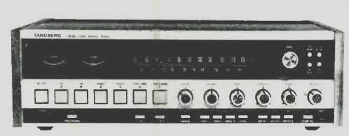
The upper section of the panel is devoted to a carefully calibrated FM dial scale (with calibration marks every 500 kHz), and AM scale, signal-strength and center-of-channel tuning meters at the left, and a tuning knob at the right coupled to one of the smoothest acting flywheel arrangements we have yet encountered. To the right of the tuning knob are four tiny push buttons which select mono FM operation, FM interstation muting, choice of 25 or 75 microsecond de-emphasis (the former required for proper listening to Dolby FM broadcasts), and offer a choice of panel lighting brightness.
The lighter colored center section of the panel is equipped with seven square pushbuttons which are easily activated by a light touch of a finger. The leftmost button turns on power, while the remaining six choose program sources including the two tape monitoring circuits which are available at the rear panel. Rotary volume and balance controls come next, followed by dual concentric bass, treble and mid-range tone control knobs, and a rotary speaker selector switch which selects one or two pairs of speakers out of the possible three pairs which can be accommodated by the TR 2075.
The lowest section of the panel contains twin phone jacks and a dozen more rectangular push buttons which take care of such less-often used functions as tape copying (from either tape deck to its alternate), loudness compensation, mono or stereo mode (including left or right only to both channels as well as L+R mono mix), low-and high-cut filter selection, and a most useful function called preamp record.
This circuit, also found on Tandberg's lower priced receiver, enables you to pre-equalize recordings applied to a third tape deck (connected via a ring-tip-sleeve phone jack nearby) by inserting the tone control circuits ahead of this particular tape output point. Finally, a twelfth button, located near the phone jacks, converts the signal-strength meter to a peak-reading power meter. A handy reference guide in the owner's manual enables the user to convert the arbitrary 0-25 secondary scale of the meter into actual watts delivered, depending upon load impedances (of speakers) connected.

Fig. 1--View of back panel.
The rear panel of the TR-2075, pictured in Fig. 1, offers a choice of DIN or phono-plug connection for both phono inputs and both tape in and out circuits. One of the phono input pairs and both tape circuits are equipped with input level controls to enable proper matching of phono cartridge or tape deck levels to built in AM or FM levels. Plug-in jumpers can be removed from the preamp-out, main-amp in jacks to permit separate use of these two sections of the receiver. Three sets of polarized speaker screw terminals are well separated from each other to prevent possible speaker cable shorts. FM and external AM terminals are also of the screw type and include 300-ohm and 75-ohm facilities for FM, along with an extra grounding terminal for the shield of an unbalanced 75-ohm transmission line. A chassis ground terminal is located near the three available convenience a.c. outlets, and a rotatable AM ferrite bar antenna is also provided.
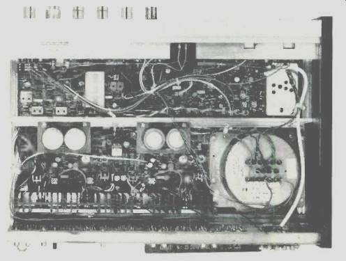
Fig. 2--Internal view.
The unique internal layout of the TR-2075 appears in the pair of photographs of Fig. 2. It is one thing to pile circuit board upon circuit board into a receiver chassis in the interest of reducing overall size, but it is quite another to make each board as accessible for servicing as Tandberg has managed to do. The entire upper front section, including dial scales, can be pivoted out of the way to disclose preamplifier and tone sections, as can be seen in Fig. 3.
Completely separate preamplifier-equalizer circuits are used for the Phono 1 and Phono 2 inputs, thereby avoiding the necessity of switching at low-level circuit points. AM and FM tuner sections are also completely independent, with a 3-gang tuning capacitor and an FET r.f. amplifier used in the former. The FM front-end employs a pair of FETs for the r.f. amplifier and the mixer stages and is electronically tuned by means of four sets of back-to-back varactor diodes. I.f. section interstage tuning is accomplished by means of a pair of solid-state filters and a TCA-420A IC is used as a limiter-quadrature FM detector. For optimum linearity, a transformer is used as the quadrature element instead of the simpler single coil often used with this IC. This detail insures extremely linear detection and results in lower distortion under controls of 100 per cent FM modulation. A Motorola MC-1210 IC forms the heart of the phase-lock loop stereo decoder section and a pair of steep bridge-T notch filters effectively suppress 19-kHz carrier signals in the output of the mpx section.
Tone control sections are of the popular Baxandall negative feedback type and cut-off filters are two active and one passive RC network. Power amplifiers are fully direct coupled and a differential input stage is used in each channel. Output transistors are operated at ±52.5 volts d.c. A dynamic time-delay circuit prevents accidental activation of the low-impedance, safety-cutout circuit when momentary signals occur at frequencies corresponding to low impedance points of the speaker's impedance characteristics. An electronic power limiting circuit is activated whenever loads below 3 ohms are presented but is unaffected by 4 ohm or reactive loads. The unit can safely sustain no-load or shortcircuit conditions at the speaker output terminals. In addition, a thermal protection circuit protects against overheating in the event of inadequate ventilation. Diode protection circuits are included as protection against transient feedback from inductive speaker loads. A center-zero voltage-sensing circuit activates a relay to protect loudspeakers from subsonic oscillation or the presence of d.c. at the output terminals. Turn-on transients are prevented from reaching the loudspeakers by means of a 4-second time-delay circuit when the unit is turned on.
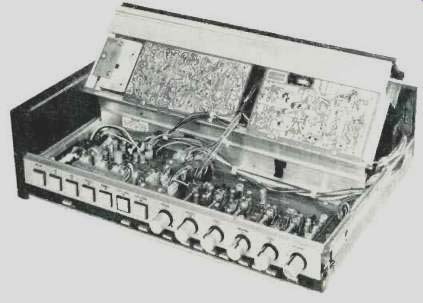
Fig. 3--View with front panel swung up for servicing.
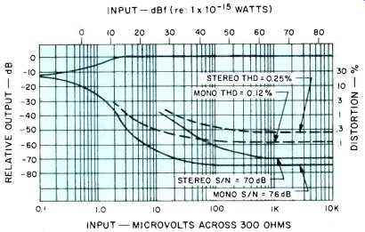
Fig. 4--FM quieting and distortion characteristics.
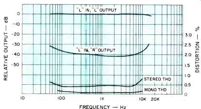
Fig. 5--Separation and distortion versus frequency.
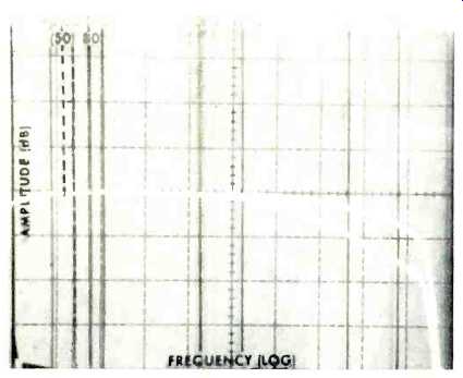
Fig. 6--Response of FM section when swept with un-preemphasized audio signals
from 20 Hz to 20 kHz. Upper curve shows 25µS de-emphasis; lower curve is
75 µS de-emphasis. Note steep 19-kHz rejection.
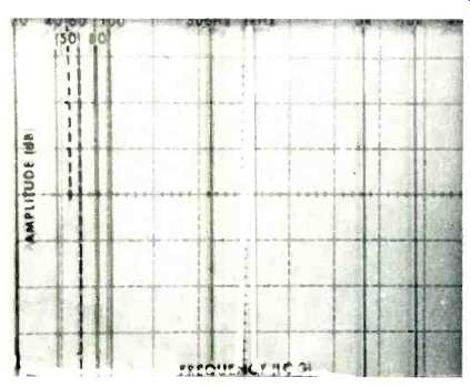
Fig. 7--Harmonic distortion content at 75 watts per channel output, both
channels driven into 8 Ohms. Distortion is primarily second-order harmonic
and is nearly 70 dB below fundamental.
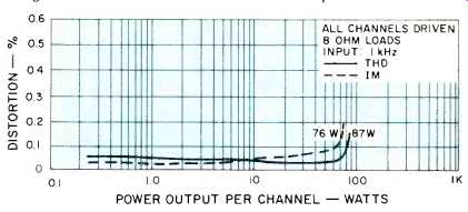
Fig. 8--Total harmonic and intermodulation distortion characteristics.
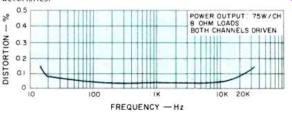
Fig. 9--Total harmonic distortion versus frequency.
FM Performance Measurements
Figure 4 depicts some of the major performance characteristics of the FM section of the TR-2075. IHF sensitivity in mono measured 1.8 µV (10.3 dBf), while stereo switching occurred just below 15 µV (28.8 dBf) as claimed. The 50-dB quieting point in mono occurred with a signal input of 3.0 µV (14.8 dBf), while in stereo that quieting was reached with a signal input strength of only 33 µV (35.7 dBf). Best signal-to-noise ratio in mono was 76 dB, while in stereo, S/N measured 70 dB, as high as our test equipment is capable of reading accurately. Capture ratio measured exactly 1.0 dB, as against 0.9 dB claimed. Alternate channel selectivity was 82 dB, while adjacent channel selectivity measured 12 dB, against 10 dB claimed. Image rejection was 70 dB as claimed while i.f. rejection was an impressive 97 dB. Sub-carrier rejection measured 62 dB.
Figure 5 plots stereo FM separation, which reached 42 dB at mid-frequencies. Distortion versus frequency is also shown in this graph for both mono and stereo reception and is seen to remain well below 1.0% even at the high frequency extreme in stereo mode. Frequency response in FM deviated by-2.0 dB at 15 kHz, a direct result of the 19-kHz notch filter which so effectively suppresses sub-carrier products at the output of the tuner section. This action, as well as the response of the FM system when set to 25 microsecond or 75 microsecond de-emphasis, is clearly shown in the sweep-frequency 'scope photo of Fig. 6.
Power Amplifier Measurements
The Tandberg TR-2075 delivered 87 watts per channel, at 1 kHz, with both channels driven into 8 ohm loads for its rated THD of 0.15%. At rated output of 75 watts, THD measured 0.05% and consisted mainly of a minute amount of second order distortion, as clearly seen in the spectrum analysis photo of Fig. 7. THD at all other power levels down to 250 milliwatts was around 0.05% or even less, as shown in the graph of Fig. 8. The same graph also plots IM distortion for various power levels, and IM reached 0.2% at a power output level of 76 watts per channel. Tandberg's statement of power band (20 Hz to 20 kHz), now required by the FTC, is an extremely conservative one. As shown in the THD versus frequency plot of Fig. 9, the power band extremes could actually have been rated as extending from 14 Hz to 32 kHz. To put it another way, if one sets the power band limits as extending from 20 Hz to 20 kHz, the "FTC power" of the Tandberg TR-2075 might well have been rated at 81 watts instead of 75 per channel.
Preamplifier Measurements
Phono input sensitivity of the variable Phono 1 inputs ranged from 2.2 mV to 9.5 mV RIAA equalization was ac curate in both Phono 1 and Phono 2 to within 0.3 dB at the high-frequency end and to within 1.0 dB at the low-frequency extreme. Overload input measured 52 mV at worst, improving, of course, as input sensitivity was reduced.
While this figure is not as good as some we have measured on competitive receivers in this price category, the presence of the input sensitivity control offsets the overload limitation. Hum and noise referred to actual input sensitivity measured 68 dB for Phono 1 inputs and 72 dB for the Phono 2 inputs. Hum and noise for high-level (tape) inputs measured exactly 82 dB as claimed (referred to a nominal 300 mV input), while residual amplifier hum and noise was less than 1 mV. The composite range of bass, mid-range, and treble tone controls is depicted in the 'scope photo of Fig. 10, while the action of the various cut-off filter combinations is shown in the tracings of Fig. 11. Note that the two high-cut filters can be used together to create yet a third roll-off characteristic at the high-frequency end of the audio spectrum (most extreme cut shown). Figure 12 displays the action of the loudness control circuitry at various settings of the master volume control and, as can be seen, Tandberg elects to boost highs (moderately) as well as lows in affecting loudness compensation.
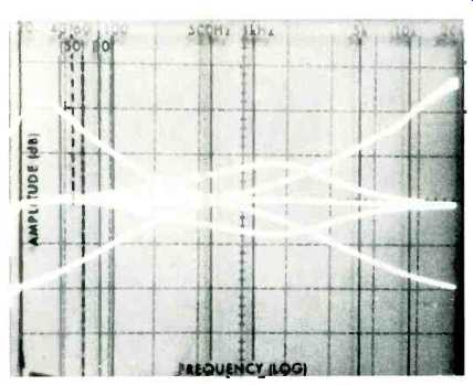
Fig. 10-Tone control characteristics.
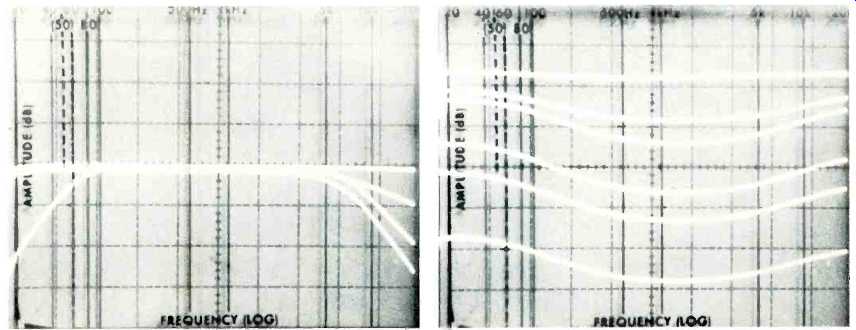
Fig. 11-Lowand high-cut filter combinations.
Fig. 12-Loudness control characteristics.
Listening and Use Tests
We used the Tandberg TR-2075 in our listening room for a period of about three weeks after completing lab measurements. The receiver has enough power to drive our low-efficiency acoustic suspension speakers (used with all higher powered receivers we test) to louder-than-life loudness levels without clipping. Controls on the TR-2075 are ideally arranged, as far as we are concerned, and our chief delight in using this instrument was that record preamp facility used in connection with the Tape 3 front-panel output jack. As might be supposed from the previously described test results, FM performance was excellent and limited only by the quality of broadcasts received. Transition from mono to stereo is positive, and muting is overcome at signal strengths of about 5 or 6µV (around 20 dBf)--just about ideal for this receiver since signals that do overcome the mute circuit are sufficiently "quiet" to be enjoyed. The inveterate "dx-er" can always defeat the mute circuits if he wishes to seek out those less usable signals of lower signal strength.
The power meter option was also worthwhile and, since we seldom rely upon a signal strength meter for tuning, we used that function during all our listening tests to confirm power levels being auditioned. The peak-reading action of the meter movement was such that we were able to read very nearly actual peak power values on all but the shortest bursts of musical transients. Having adjusted phono and tape inputs by means of those input level controls, we fully appreciated their inclusion and wished that less expensive receivers could afford this luxury as well. It's comforting not to have to grab for the volume control every time we switched from one program source to another. Clearly, the Tandberg TR-2075 is an example of a higher priced receiver that should not be judged on a simple "dollars per watt" basis.
Admittedly, there are lower priced receivers that offer as much or even more power per channel, but the TR-2075 has so much more going for it than power output that we urge interested readers to experience "hands on" auditioning of this fine piece of equipment before deciding that its price may be too high for a "75 watt per channel" integrated receiver. Actually, the receiver should be thought of as a top performing tuner and an equally good amplifier which happen to have been constructed on a single well-designed chassis. Taken in that light, the Tandberg TR-2075 becomes rather a bargain at its $1,100.00 suggested retail price.
-Leonard Feldman(Adapted from: Audio magazine, Mar 1976)
Also see:
Tandberg Model TR-2040 Stereo FM Receiver (Jun. 1978)
Tandberg Model TR-1055 FM/AM Stereo Receiver (Jul. 1974)
Tandberg TR 1020 Receiver (Feb. 1973)
Tandberg 3080A FM Receiver (Equip. Profile, July 1989)
Tandberg Compact Disc Player (Nov. 1987)
Tandberg TCA 3018A Preamp and TPA 3026A Amp (Apr. 1987)
Tandberg 3008A Preamp and 3009A Amp (Jan. 1986)
= = = =