by M.J. Salvati
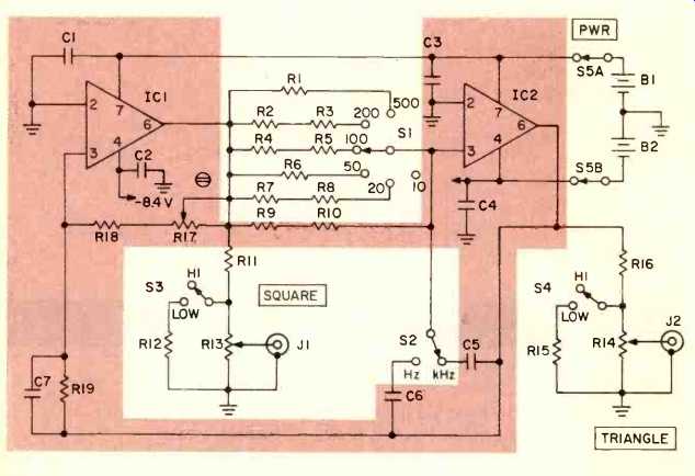
Fig. 1--Schematic diagram; shaded area indicates parts on circuit board.
===========

Table I--Specifications.
Frequencies: 10, 20, 50, 100, 200, 500 Hz, and 1, 2, 5, 10, 20, 50 kHz.
Frequency Response: ±0.3 dB.
Output Level (HI) : 0-3 V p-p into 10 kilohms or higher.
Output Level (LO): 0-300 mV p-p into 10 kilohms or higher.
Square Rise Time: 600 nano seconds.
Square Fall Time: 600 nanoseconds.
Power Requirements: Two 8.4-volt batteries.
===========
This article describes the construction and operation of a battery-powered signal source that provides very clean square-wave and highly linear triangle-wave outputs. The quality of the output signals compares very favorably with commercial function generators selling in the $100.00 to $150.00 price range. Full specifications are given in Table I.
This little generator is designed for use in repair and adjustment of amplifiers and performance testing of hi-fi components and systems. The square-wave output is useful for checking the frequency response of power amplifiers and preamplifiers, as well as for checking the transient response of these items and speakers. The triangle waveform is superior to a sine-wave test signal for observing clipping and overload.
Theory of Operation
Op-amp IC1 generates a square wave by positive feedback through resistors R17/R18 to its noninverting input (pin 3). This square wave is integrated by op-amp IC2 to produce the triangle wave. Op-amp IC2 also controls the switching point of IC1 by feedback through resistor R19. The integration frequency (hence that of the triangle and square waves) is deter mined by resistors R1-R10 and capacitors C5 and C6.
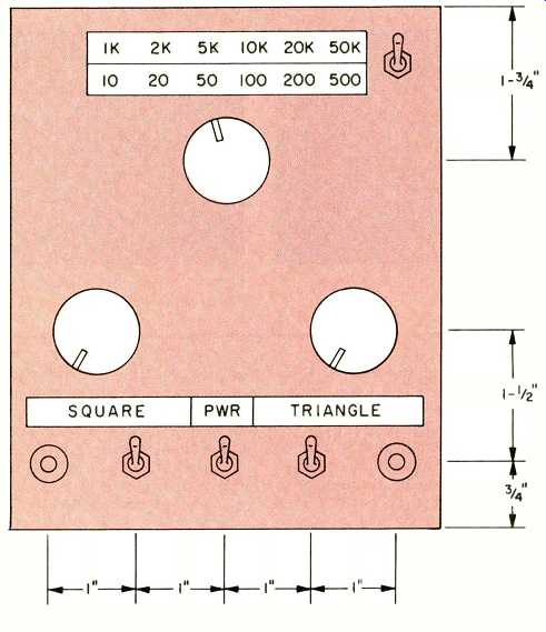
Fig. 2--Suggested layout for front panel.
Variations in the resistance of R17/ R18 affect both frequency and triangle output amplitude in this design, and this effect is used to advantage in this present circuit. Here, the frequency can be adjusted so that readily avail able values of R and C yield the desired spot frequencies. The value selected for R16 yields the desired triangle output level from the resulting circuit constants.
Switches S3 and S4 connect low-value resistors across the output pots (R13 and R14) to reduce the available output voltages by 20 dB.
The ICs have FET inputs, so the bias current of IC2 cannot upset the circuit operation when high-value integrating resistors are used. This allows using resistors as high as 400 kilohms (R9 and R10) and as low as 8 kilohms (R1 in parallel with R9/R10), which in turn allows using the same capacitors to cover many frequencies. Just two integrating capacitors (C5 and C6) cover nearly four decades of frequency. The resulting system with six spot frequencies per range also has a practical ad vantage in that it allows using readily available switches.
Simplicity and practical accommodations were stressed throughout the design of this generator. If the output of IC1 were zener clamped, the output amplitudes could be stabilized against supply-voltage changes. However, with suitable zeners, this occurs only at higher supply voltages (ruling out battery operation), and then the sup ply-voltage variations affect frequency (not the case with the chosen design).
Furthermore, for 50-percent duty cycle (inherent in this design), the zeners must be closely matched. Therefore, I opted for this simple design, using mercury batteries (which have a very flat discharge characteristic) to take care of the supply-variation problem.
Construction Notes
As far as layout is concerned, nothing is especially critical. Even packaging is easy; to accommodate the switches, connectors, and frequency scales, a cabinet much larger than needed for the "innards" is used.
Thus, you will have no problems fit ting the batteries and circuit board in side. The frequency scales and other front-panel nomenclature are Dymo type labels. See Fig. 2 for suggested layout.
The components covered in tone on the schematic diagram are mounted on the circuit board. Use No. 22 solid wire and resistors R11 and R16 to make the connections from the circuit board to the cabinet-mounted parts. The stiffness of the connections will sup port the tiny and lightweight circuit board. Perforated board or printed-circuit techniques can be used for the circuit board, but I recommend Veroboard by Vero Electronics. The metallized 0.1-inch grid pattern accepts DIP ICs directly and it also permits dense packaging.
The frequency accuracy depends on component quality. For most applications 5-percent tolerance resistors and 10-percent capacitors will do nicely.
However, for best performance, use 1-percent metal-film or deposited-carbon resistors and temperature-stable capacitors for C5 and C6.
Switch S1 should have shorting contacts for transient-free frequency selection. However, because resistors R9 and R10 are hard wired in this design, the worst that can happen if you use a switch with non-shorting contacts (such as the Radio Shack 275-1386) is a few cycles of 10-Hz signal while switching. This is one of the many de sign accommodations made for constructors who do not have access to large industrial parts-supply houses.
Consumer-oriented mail-order houses can supply most, if not all, of the parts. I obtained the FET op-amps and ceramic capacitors from Digi-Key and the switches and connectors from the local Radio Shack. Digi-Key's address, for those who don't have it, is P.O. Box 677, Hiway 32 South, Thief River Falls, Minn. 56701.
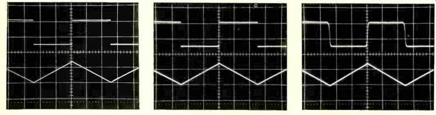
Fig. 3-Square and triangle waves at 10 Hz, 20 mS/div.
Fig. 4-Square and triangle waves at 1 kHz, 0.2 mS/div.
Fig. 5--Square and triangle waves at 50 kHz, 4 uS/div.
Adjustments
The circuit will oscillate without adjustment or start-up procedures. However, there are optimization procedures in regard to frequency accuracy and frequency response.
Trim pot R17 permits precise adjustment of average operating frequency.
If a counter is available, set the generator to 1 kHz and adjust pot R17 until the counter indicates 1000. If a counter is not available, a triggered-sweep scope with accurate timebase will do.
Adjust R17 for a 1-millisecond period of the generator's square wave as displayed on the scope.
Capacitor C7 improves the high-frequency performance of the circuit. It has greatest effect at 50 kHz and progressively less effect at lower frequencies. Below 2 kHz, it has negligible effect. Increasing the value of C7 increases the frequency of oscillation and lowers the triangle output amplitude. Conversely, decreasing the value of C7 lowers the frequency and increases the triangle output amplitude.
The exact value that yields maximum high-end frequency accuracy and flat test frequency response depends to some extent on the construction technique employed. The indicated value (180 pF) is fine for most applications, as evidenced by the Table of Specifications. However, if super-flat frequency response and high-end frequency ac curacy are important, connect a wide-band voltmeter to the triangle output and a frequency counter to the square-wave output. Then change C7 as directed above until the 50-kHz frequency accuracy and triangle amplitude are the same as at 1 kHz.
Use
Applications of this generator were mentioned earlier. However, there are certain points of usage you should note. Since the output level controls are linear pots, it is important to use the HI-LOW switches to attenuate the signal when driving preamps, integrated amplifiers, and receivers. The HI position is intended only for driving power amplifiers.
Both triangle and square wave are simultaneously available, and their levels are set independently. When using one of the outputs to drive an amplifier under test, use the other output to trigger the scope. This gives a stable scope display regardless of how much you vary the test signal level.
================

Table II-Parts list with some suggested commercial parts.
IC1--National Semiconductor LF357.
IC2--National Semiconductor LF356.
B1, B2--8.4-volt mercury battery, Eveready E146.
J1, J2--RCA-type phono jack, Radio Shack 274-346.
S1-6--position, 1-pole rotary switch with shorting contacts (see text), Centralab 1400.
S2-S4--SPDT miniature toggle switches, Radio Shack 275-613.
S5--DPST miniature toggle switch, Radio Shack 275-614.
C1-C4--0.1-pF, 25-V disc ceramic capacitors, Panasonic DE104.
C5--1000-pF ±2% mica capacitor (see text).
C6--0.1-uF ±5% polystyrene or polycarbonate capacitor (see text).
C7--180-pF mica or ceramic capacitor (see text).
R1--8.2-kilohm, 1/4-W film resistor.
R2--20-kilohm, 1/4-W film resistor.
R3--1-kilohm, 1/4-W film resistor.
R4, R5--22-kilohm, 1/4-W film resistors.
R6--100-kilohm, 1/4-W film resistor.
R7--R10-200-kilohm, 14-W film resistors.
R11--3.3-kilohm, 1/4-W carbon resistor.
R12--91-ohm, 1/4-W carbon resistor.
R13, R14--1-kilohm potentiometers, Centralab B-5.
R15--82-ohm, 1/4-W carbon resistor.
R16--2.2-kilohm, 1/4-W carbon resistor.
R17--5-kilohm trimmer potentiometer.
R18--13-kilohm, 1/4-W carbon resistor.
R19--10-kilohm, 1/4-W carbon resistor.
6 x 5 x 4 inch aluminum case, Bud CU-3007A.
Knobs with index mark, three required.
9-V battery connectors, two required.
================
Source: Audio magazine, Jan. 1981)
Also see:
Performance of High Energy in Magnetic Materials in Audio Cassette Recording Tapes (Sept. 1978)
= = = =