Manufacturer's Specifications:
Dimensions: 5 1/4 in. diameter x 13/16 in. thick (13.3 cm x 2.1 cm).
Price: $85.
Company Address: Terk Technologies, 56 Harrison St., New Rochelle, N.Y. 10801, USA.
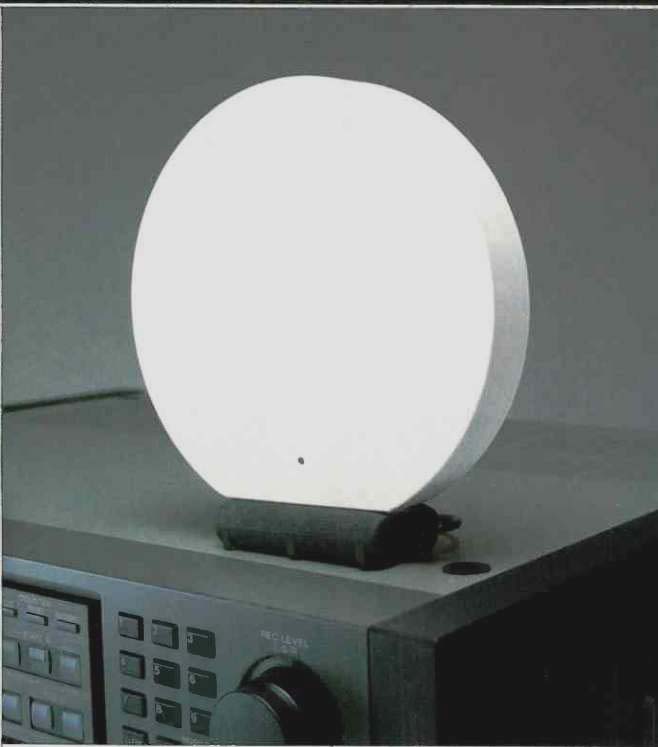
When I first saw the new Terk Pi indoor FM antenna, I was sure that it couldn't do as good a job of receiving FM signals as an ordinary, simple wire dipole. I was even more convinced that this little disc-shaped antenna couldn't compete against a properly oriented rabbit-ears unit. Considering that my good friend Larry Schotz had done the electronic design, I should have known better. It is a truly amazing product! Offered in a choice of white or gray matte finish, the Pi is not much larger in diameter than a Compact Disc. Its size and shape make it possible to place the unit anywhere-even on top of a tuner or receiver, or on the shallowest of shelves. This antenna's unusual styling, as important a feature as its performance, was a joint effort of Neil Terk, an award-winning industrial and graphic designer turned manufacturer, and John Lonczak, another accomplished industrial designer. As for the electronics, the Pi incorporates a low noise amplifier, developed by Schotz, that provides up to 30 dB of gain.
The circular antenna rests in its horizontal position for omnidirectional reception, or can be positioned vertically and oriented for best reception of weaker signals. A 75-ohm shielded cable carries d.c. operating power and the received r.f. signal back to the FM tuner or receiver. The unit comes with its own impedance-matching transformer and a separate a.c. power adaptor. If your tuner or receiver is equipped with a switched a.c. receptacle, the adaptor can be plugged into it.This antenna will then draw power only when the tuner or receiver is turned on. However, even if you leave the a.c. adaptor plugged into a live receptacle at all times, it's not likely to affect your electric bill much, as the Pi consumes only a watt or so of power.
Little information was supplied regarding technical specifications, but then again, proof of performance was easy enough to establish. My tests consisted of measurements of the Pi versus the performance of a standard, indoor wire-dipole antenna, followed by extensive listening tests.
Measurements and Listening Tests
To conduct the comparison tests, I mounted a simple dipole on an outside wall of the lab, orienting it for best reception of station signals arriving from the west. (The lab is about 20 miles directly east of New York City, where most local stations' transmitting antennas are located.) Using a Blonder-Tongue Model FS-2 field strength meter, I tuned in several signals and noted their frequency and their indicated signal strength. The field-strength meter's most sensitive full-scale readings are 100 µV, so it is easily possible to read down to 10 µV if necessary.

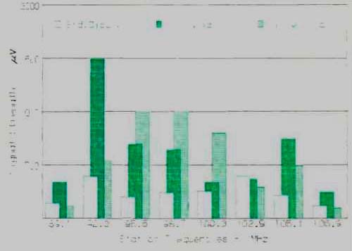
Fig. 1--Performance comparison between the Terk Pi, in horizontal and vertical
orientations, and a simple dipole antenna.

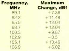
Table I--Signal-level changes for Terk Pi antenna relative to a wire dipole.
Next, I connected the Terk Pi antenna to the meter and tuned to the same frequencies as before. I alternately measured the signal strength when the Pi was positioned vertically and oriented for strongest signal and when it was mounted horizontally, flat on the test bench. The results, seen in the bar graphs of Fig. 1, pretty well speak for themselves. For all but one of the signals (102.9 MHz), the Pi, in one or both of its mounted positions, outperformed the dipole. In five out of eight cases, improved performance, compared with the dipole, was noted regardless of the Pi's orientation. For two of the remaining stations, the signal strength was actually higher with the Pi in its horizontal (omnidirectional) position than when it was set vertically and oriented for maximum signal strength. Perhaps these two stations are transmitting only horizontally polarized signals. Table I shows how the signal strengths pulled in by the Terk, in its best orientation for each of eight stations, compared with those from the simple dipole antenna. Note that the Terk’s signal was significantly greater on all but one station, and only marginally poorer on that lone exception.
As impressive as these results may be, the real proof of performance comes in the listening tests. It is relatively easy to add an r.f. amplifier to an antenna and thereby boost apparent incoming signal strengths as measured on a field-strength meter. Unfortunately, in the past, many antennas that used this approach amplified the noise as much as the desired signal.
Since FM performance is judged primarily in terms of signal-to-noise ratio, such boosters were of little or no practical use. The nice thing about this Schotz-designed circuit is that, even though it amplifies the incoming signal, its own noise factor is so low that it makes the signal sound quieter than an amplified dipole would.
Am I suggesting that the Terk Pi antenna can replace a multi-element outdoor FM antenna? Of course not. But for the apartment dweller who is not permitted to install an outdoor antenna or even for the homeowner who prefers not to, the Terk Pi is as nicely styled and as effective an indoor FM antenna as you are likely to find. Having something that looks as good as this and works well, too, is a rare treat.
-Leonard Feldman
(Adapted from: Audio magazine, Feb. 1989)
Also see:
Terk Technologies Model Pi2 FM Antenna (Nov. 1990)
Terk 8403 FM Antenna (Jan. 1986)
Antennas FM -- Try a Rhombic FM Antenna (Jan. 1982)
Kill FM Interference With Two Antennas (Jan. 1980)
FM Fidelity: Is The Promise Lost? (March 1985) and The Problem with FM (March 1985)
= = = =