Manufacturer's Specifications:
Amplifier Gain Range: -20 dB to +38 dB.
Twin-Tone Modulation Distortion: Less than 0.1% at 100 mV input.
Noise Figure: 1.5 dB.
Impedance: 75 ohms, adaptable to 300 ohms.
Output Matching Accuracy at 75 Ohms: SWR (Standing Wave Ratio) less than 1.2:1.
Operating Frequency Range: 88 to 108 MHz.
Pickup Pattern: Directional or omnidirectional.
Dimensions: 5 in. in diameter by 1 in. thick.
Price: $79.95.
Company Address: 56 Harrison Street, New Rochelle, NY 10801.
It's been some time since I tested the Terk Technologies Pi indoor FM antenna, and when Editor Gene Pitts asked if I thought it might be worth testing the second generation model of that unique amplified indoor FM antenna (appropriately called the Pi2), my first reaction was that it probably was only a cosmetic change over the earlier design. Just to make certain that I wasn't being too cynical, I put in a call to Larry Schotz, the well-known designer who created the electronics for the original Pi antenna and who was also responsible for its redesign.
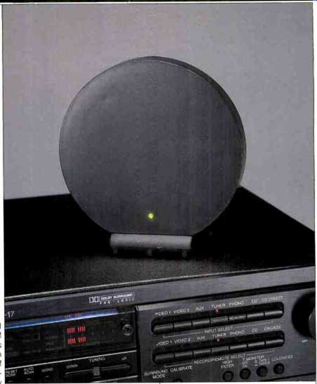
Schotz assured me that the Pi2 had a lot more going for it than did the original Pi. Since I have never known him to exaggerate (when it comes to his r.f. designs, if anything, he tends to be too modest), I decided a test of the new design might be in order. In terms of its appearance, the Pi2 is about the same size as its predecessor--not much larger in diameter than a Compact Disc. Its size and shape make it possible to place the unit anywhere, even on top of your tuner, receiver or on the shallowest of shelf arrangements.
About the only physical difference I could detect between this model and the earlier Pi was a small foot on the rear of the circular antenna housing, near the top of the housing when the antenna is upright, in its directional receiving mode. When the Pi2 is laid flat for omnidirectional reception, it rests on this foot and the edge of the smartly styled built-in stand. I soon discovered, however, that this little supporting foot is also the knob of a control that varies the gain of the amplified antenna from -20 to approximately +38 dB. Why would you ever want to have "negative gain" (otherwise known as a loss in signal strength) with an indoor FM antenna? I'm sure anyone who lives within a few hundred yards (or even a mile or two) of an FM station's transmitter can answer that. As my late mentor Murray Crosby used to say, under those conditions, "you can pick up the signal with a wet string for an antenna." There are times when so much signal is an undesirable thing, and that's when the counterclockwise setting of the little knob on the Pi2 is welcomed.
Still, most purchasers of this little indoor FM antenna will probably choose it for its ability to amplify weak FM signals without adding noise, and it was with that purpose in mind that most of my tests were conducted. The circular antenna rests in its horizontal position for omnidirectional reception or, optionally, it can be positioned vertically and oriented for best reception of weaker signals. A single 75-ohm shielded cable to the antenna provides operating power for the antenna and also carries the received r.f. signal back to the FM tuner or receiver. As was true of the earlier model, the Pi2 comes with an impedance-matching transformer and with a separate power adaptor. If your tuner or receiver is equipped with a switched a.c. receptacle, the adaptor can be plugged into such a receptacle and will then only draw power when the tuner or receiver is turned on. However, even if you leave the a.c. adaptor plugged into a live receptacle at all times, it's not likely to affect your electric bill much, as the Pi2 consumes only a watt or so of power.
My tests consist of measurements and comparisons of the antenna against the performance of a standard indoor wire-dipole antenna. Once I've satisfied myself that the powered antenna actually increases signal levels available at the antenna input of a tuner, I subject the antenna to extensive use and listening tests. I'll have more to say about those tests shortly.
Measurements

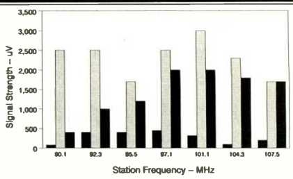
above: Signal-strength comparisons. For each station, left-hand bar
shows signal strength with standard dipole, center (shaded) bar shows results
with Pi2 in directional mode, and right bar shows Pi2 in omnidirectional mode.

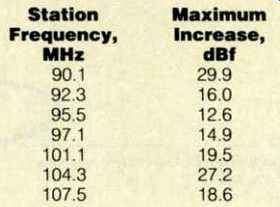
Table I--Increase in signal strength with Terk Pi2 in directional mode, oriented
for maximum pickup, compared to reference dipole.
To conduct the comparison tests, I mounted a simple dipole antenna on an outside wall of the lab, orienting it for best reception for station signals arriving from the west. (The lab is located almost 20 miles directly east of New York City, where most of the station transmitting antennas in my area are located.) Using a Blonder-Tongue Model FS-2 field-strength meter, I tuned in several signals with the dipole connected to the field-strength meter and noted their frequency and their signal strength.
Next, I connected the Terk Pie antenna to the field-strength meter and tuned to the same frequencies as be fore, alternately orienting the Pi2 for strongest signal when it was vertically positioned and also measuring signal strength when the antenna was mounted horizontally (flat on the test bench). The results, depicted in the bar graphs of Fig. 1, pretty well speak for them selves. For all of the signals checked, the Pi2 outperformed the dipole, regardless of the Terk antenna's orientation. For one signal frequency (107.5 MHz), the horizontal (omnidirectional) orientation provided the same signal strength as I got from the vertical (or directional) orientation after I had aimed it for maximum signal strength.
Table I shows the maximum improvement in signal strength, compared to the reference dipole, when the Pi2 was oriented for greatest signal strength.
I checked back to my test results for the original Pi antenna and found that for those station frequencies common to both tests, results were consistently better with the Pi2--in some cases by as much as 6 dB or more.
Use and Listening Tests
As impressive as the lab results may be, the real proof of performance comes in the listening tests. FM performance is judged primarily in terms of signal-to-noise ratio, and if an amplified antenna adds as much noise as it does increased signal levels, it is worthless. The nice thing about this latest Schotz-designed circuit is that, while it amplifies the incoming signal, it adds less noise than my tuner's frontend, so I get quieter results listening with this amazing little antenna than when using a passive dipole. (Editor's Note: Under worst-case conditions in mid-town Manhattan, I found that the Pi2 was a touch noisier than a set of passive rabbit ears, that the Pi2's attenuator was effective in dealing with overly strong stations, and that antenna orientation wasn't a question with the Pi2 because of the extreme level of multipath in my area. -I.B.) However, perhaps the most amazing fact about this new and much improved version of the Pi antenna concept is that it carries the same suggested retail price as the earlier model, yet runs rings around it in actual performance.
In my listening tests, with the Pi2 hooked up to my reference tuner, I was able to log 48 usable signals, 45 of them in acceptably noise-free stereo.
Since I am at a pretty good distance from most station transmitters, I found no need to turn down the gain of the amplifier stage to overcome overload conditions. I am fairly certain, however, that many users of the Terk Pi2 will find this "negative gain" capability to be a very positive feature. As in all my previous tests of .indoor FM antennas, I am not suggesting that the Terk Pi2 can adequately replace a multi-element outdoor FM antenna. But as was true with the less formidable Terk Pi, for the apartment dweller who can't install such an outdoor antenna or even for the homeowner who prefers not to, the Pi2 goes far beyond any similarly sized antenna that I've measured. Its small size should appeal to the less technically oriented members of the family, while its performance is sure to please the FM radio enthusiasts in the household.
-----Leonard Feldman
(Source: Audio magazine, Nov. 1990)
Also see:
Terk 9600 Pi FM Antenna (Feb. 1989)
Terk 8403 FM Antenna (Jan. 1986)
Antennas FM -- Try a Rhombic FM Antenna (Jan. 1982)
Kill FM Interference With Two Antennas (Jan. 1980)
FM Fidelity: Is The Promise Lost? (March 1985) and The Problem with FM (March 1985)
= = = =