- Audioclinic, Joseph Giovanelli
- Fundamental Audio, Martin Leynard
- Audio ETC, Edward Tatnall Canby
- Letters
- Editor's Review
- Tape Guide, Herman Burstein
- Sound & Sight, Harold D. Weiler
-------------
AUDIO CLINIC

by Joseph Giovanelli
If you have a problem or question on audio, write to Mr. Joseph Giovanelli at AUDIO, 134 North Thirteenth Street, Philadelphia, Pa. 19107. All letters are answered. Please enclose a stamped, self-addressed envelope.
Tuner Muting Control
Q. What is the muting control on a tuner?
John J. Kiesel, Valley Stream, L. I., N. Y.
A. A muting control on a tuner is used to quiet interstation hiss when the tuner is changed from one station to another.
There are various schemes by which this is accomplished. Basically, what is done is to cut off one of the audio stages in the tuner so that the hiss cannot be transmitted, but the signal can be passed along. One common arrangement is to set a tube up so that when no voltage appears on its grid, the tube is highly conductive. The cathode of this tube is connected to the cathode of an audio amplifier. Because of the high conduction of the control tube, the cathodes of both tubes are positive with respect to the grid of the audio tube. The grid of the control tube is connected to the grid of the first limiter amplifier. Therefore, when a signal appears, the limiter grid goes negative. This causes the control tube to become less conductive. The audio tube is no longer cut off and the circuit performs as a normal audio amplifier.
Sometimes a neon lamp is introduced into the plate circuit of the control tube.
Such a lamp has the property of going into heavy conduction suddenly. What this does, therefore, is to eliminate the tendency of the audio amplifier to be cut off gradually; cutoff will occur suddenly, at the moment the lamp "fires," or ignites.
There are other similar schemes which involve the use of a relay in the plate circuit to accomplish the sudden turn-on and turn-off characteristics which are desirable in such circuits. The contacts of this relay are placed in the audio section of the tuner in such a way as to short out the signal when only noise is present.
In sophisticated communications type receivers, the muting, or "squelch," circuit is so arranged that the noise is amplified separately and fed into the control amplifier. Added noise will only make the control tube open the circuit further rather than allow noise to enter, as is often possible with the less sophisticated muting arrangements. This sort of noise-gating arrangement is quite involved, but it works well in communications equipment. I have not seen it used in FM tuners.
Speaker Impedance
Q. I have a stereo music system.
My speakers are of the multiple-array type, each channel using 25 6-inch speakers in series-parallel in the midrange, plus six, hard-core tweeters in the treble section. I also have a University Sphericon tweeter in each channel to take care of the ultra highs. My low frequencies are produced by a 12-inch, dual-voice coil woofer.
In each channel I use a 2-way crossover network. I would appreciate a simple, accurate method which would give me the right impedance values of the various elements in the system. I do own a VTVM.
Adam Kohihoff, Clearwater, Fla.
A. The VTVM you own will be of help in telling you the impedance of your speaker system, but it is useless unless you have access to an audio oscillator.
This instrument is connected to the input of your amplifier and it is a source of signal for the tests to be outlined here.
The impedance of your system may vary considerably over the frequency range because of the presence of the crossover network and because of the inductance and mechanical resonances in the speakers themselves. You may notice the greatest departure from an average impedance in the midrange and perhaps in the upper portion of the audio spectrum because of the many speakers involved. Once you know the average impedance of the entire system, you can connect the system to the amplifier tap which most closely resembles the impedance that you have determined.
You do have a complication in your particular system because you appear to be trying to employ a two-way crossover to work with a three-way speaker system.
I do not know how this was done. It seems to me, however, that this was not the best approach to obtain proper operation of a three-way system. You can make an improvement in the impedance curve by obtaining a crossover network which is designed for a three-way system.
If the network uses an 8-ohm impedance as a design center, use speakers of 8 ohms impedance. In the case of the 25 speakers connected in series-parallel, they must be connected in such a manner as to provide an impedance of as nearly 8 ohms as possible. If the impedance of the speakers does not match that of the crossover network, the crossover point will be moved from its design frequency and the sharpness of the roll-off will change.
Now we come to what you wished to know specifically-the method for determining the impedance of the various speakers in your system.
Obtain a potentiometer whose ohmic value is of the order of 50 ohms. Connect as you would a rheostat, in series with your speaker or speaker array. Feed a signal of, say, 400 Hz into the amplifier so that the output voltage appearing across the amplifier is one or two volts.
Adjust the potentiometer so the voltage across it just equals that produced across the speaker terminals. The resistance of the pot at this point will be equal to the impedance of the speaker at 400 Hz. Try various other frequencies in the range to be covered by the particular speaker under test, including the crossover frequencies. You will be able to determine the smoothness and sharpness of the impedance curve of the individual speakers and of the speaker system as a whole.
The smoother and the flatter this curve, the better the speaker system will be.
Intermittent Hum
Q. Several months ago I started getting an intermittent hunt in my amplifier. The amplifier would be working quietly on records or on FM. Suddenly a loud hum would be heard for a few seconds and then stop just as suddenly. The periods it would remain on gradually grew longer, until it would stay on for 20 seconds or more, and then disappear for a couple of minutes. I asked the manufacturer about this. The company recommended checking the tubes. I did this and found that one output tube had a short. I replaced the tube. Still the hum persisted.
I took the amplifier to the repair department of a leading high-fidelity dealer. He kept it a week and found that the trouble was caused by three defective 12AX7 tubes-cost $12.00. (1 did not mind the bill if I could have gotten rid of the hum, but it is still present.) In addition, I replaced the rectifier tube which seemed to induce hum when I tapped it.
I wonder if you have any ideas on this problem?
William C. Day, Cincinnati, Ohio.
A. When we think of hum of the type you have described, filter capacitors come to mind as the thought first and foremost after tubes have been checked.
The filter may be fine in terms of having its rated capacitance but it may have loose contacts. The lugs on the bottom of the capacitors often are not well soldered or riveted. This can lead to intermittent operation of the capacitor. Tap the capacitors rather severely and see what happens. If the hum comes and goes in accordance with your tapping, you have probably found the trouble.
Be sure that when you tap something that you attribute your actions to what you hear. To illustrate this, you tapped the rectifier tube and noticed the hum coming and going. Perhaps what really was taking place was that the vibration caused by the tapping of the tube was transmitted to the defective component via mechanical shaking of the chassis.
Make sure that this is not what is happening when you tap a particular capacitor can. Look for the component which appears to be most sensitive in terms of affecting the hum heard in the speakers.
Unfortunately, you sometimes will not be able to produce the hum in the manner just described. It may be a function of heat rather than something which is mechanically loose enough to show up when tapped. You might be able to cause the failure of the weak part merely by increasing the line voltage to the amplifier by 10 percent. This can easily be done by a power-control auto transformer, if one is available. If the component fails altogether, you can find the trouble more easily than you can when the condition is intermittent. This kind of servicing is the most difficult.
Hence, it is also the most expensive. It is not surprising, then, that a service shop, after spending a considerable amount of time on the equipment believes that the trouble has been found, only to be proved wrong later on.
There is another tracing scheme which I have not seen used very much, but it is one which I like to use at times.
It involves placing a pair of headphones or the input of another amplifier across the B supply at various B plus points. Naturally, the input of the headphone amplifier is coupled to the circuit via a capacitor. The idea is to note whether the hum is heard in the phones at the same time it is heard in the speaker of the offending amplifier. By connecting to various B-plus points, you can find the one which produces the greatest amount of hum. The chances are good that this portion of the circuit is defective.
New Literature
One of the latest of the Allied Publications is this 96 page book. Titled "Using Your Tape Recorder," the book covers the following chapters:
Sound
What Is It?; Your Recorder; Microphone Recording; Recording 'Off the Air'; Dubbing from Records and Tape; Editing; Sound and Special Effects; Sound for Slides and Home Movies; Recorder Maintenance. The author is an old hand at writing entertaining and instructive audio manuscripts. He is our own Harold D. Weiler-to be found here each month in SOUND AND SIGHT. Price of the paperback volume is 50 cents postpaid directly from Allied Radio Corporation, 100 N. Western Avenue, Chicago 80, Illinois.
Decorating With Consoles
H. H. Scott has just announced a free brochure entitled "At Home with Stereo." This full-color 20-page publication is in fact a catalog of the expanded Scott line of stereo consoles. Each is mounted in an exclusive collection of decorator-styled room settings. Included are many informative articles on high fidelity, the role of music in the home, choosing the correct console to match individual room decor, and complete explanations in non-technical terms, of the more technical aspects of stereo consoles. Check 5.
VTVM-VOM Guide
A new twelve-page Triplett test equipment catalog describes a line of panel and portable electrical and electronic test instruments. The catalog defines a selection of instruments including VOMs, combination VOM-VTVMs, laboratory and burnout-proof VOMs, and other instruments. Photos and complete technical details are given for each item. Also listed are accessory items and carrying cases, and list prices. This is catalog 49-T; it is free, and may be ordered from the Marketing Department, The Triplett Electrical Instrument Company, Bluffton, Ohio 45817.
++++++
The 7th AUDIO ANTHOLOGY
Edited by C. G. McProud, publisher of AUDIO. Includes ten articles on transistor design, stereo tuner alignment, audio measurements, two transistorized audio voltmeters you can build, and more, much more.
This is a meaningful reference for everyone in the fields of audio engineering, recording, broadcasting, manufacturing, and servicing of components and equipment. It's a necessary book for the high-fidelity enthusiast. 144 fact-filled pages. Only $2.00. AUDIO Bookshelf 134 N. 13th Street, Phila., Pa. 19107 Please send me the Seventh AUDIO ANTHOLOGY. I am enclosing the full remittance of $2.00. (No. C.O.D. or billing.) Name, Address, City , State Zip
---------------
++++++
Fundamental AUDIO
Martin Leonard
How do sounds differ? In loudness, of course, and in frequency (or pitch) both of which we've covered in the last two installments of "Fundamental Audio." But not all sounds of the same frequency and amplitude sound the same: "A" on a violin is quite plainly different from "`A" on a trumpet; Callas and Sutherland sound different even when holding the same note from the the same aria. What gives each sound its individual character? Basically, only two characteristics: harmonic content (the number, variety and intensity of frequencies besides the fundamental one which sets the pitch), and wave envelope (the shape of the imaginary line drawn along the peaks of the waveform from its beginning to its end). Let's look first at harmonic content.
Back in January, we showed a typical music waveform and said that "despite its jagged shape, it can be analyzed into its component sine waves." A look at a vibrating string will show us why.
If we pluck a string whose ends are fixed, it will flex up and down continuously along its length (Fig. 1A). The main frequency of this flexing (which is determined by the length, mass and elasticity of the string) is called its fundamental vibration, and the resulting tone is what we hear as the pitch of the string.
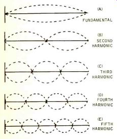
Fig. 1. The basic way in which a pure wave, and then a wave plus progressive harmonics, is generated.
MORE ON WAVES
But this is not the only frequency at which it vibrates. There are, in addition, several higher frequencies-all exact multiples of the fundamental-called harmonics. The "second harmonic," whose frequency is exactly double that of the fundamental, arises because the string also tends to vibrate in two segments whose effective lengths are each half that of the entire string (Fig. 1B). The string also vibrates as though it were divided into three, four, five and more sections, and the resulting vibrations are known as the third, fourth, and fifth harmonics and so on.
All of these "overtone" vibrations occur at the same time as the fundamental, and are superimposed upon it. And because each of these overtones is both higher (and therefore faster) and weaker than that of the fundamental, their vibrations are usually close to impossible to see (except on very low strings, whose fundamental and overtone vibrations are slower than those of high strings) . In Fig. 1, for clarity, we drew each of the string's harmonic vibrations with equal amplitude. Though this might seem to imply that all of a string's harmonics are equal in amplitude (and volume) to the fundamental, this is far from being the case. In practice, some of these harmonics are louder than others, and none of them is as loud as the fundamental.
This is important, for these harmonics (and other overtones) give different sounds their individual characters, or timbres; without them we would be unable to tell one instrument from another.
Stringed instruments, as Fig. 1 indicated, produce all the odd and even harmonics. So do open-pipe instruments.
Closed pipes, however, will not produce the even harmonics (2nd. 4th, 6th, etc.) although they do produce the odd ones.
Harmonics, those overtones that are exact multiples of the fundamental frequency, are not the only overtones produced by musical instruments. The first overtone of a tuning fork, or other "clamped bar" is 6.27 times the fundamental frequency, the second overtone is 17.55 times the fundamental. That of a xylophone, or other device using a free, or un-clamored bar. is 2.76 times the fundamental, its second overtone being 5.4 times the fundamental frequency. Drums and similar membranes have similarly inharmonic overtones, such as 1.59 and 2.3 times the fundamental. Gongs, cymbals, and other circular plates produce different overtones (though still inharmonic) depending on how they are supported when struck.
Not all of these overtones are heard, by any means. To begin with, since each overtone is higher than the preceding one, the uppermost overtones are beyond the limits of human hearing. This will affect the overtones of higher notes more quickly than it will low ones: one might conceivably hear the 40th harmonic of a 440-hertz "A" (17,600 Hz.) but the 6th harmonic of the piano's highest "A'' (3520 Hz.) would be a very inaudible 21,120 hertz.
And as the overtones get higher, they become weaker. Fig. 2 shows the waveform and a frequency spectrum diagram for a clarinet note. The spectrum diagram shows the relative amplitudes of the clarinet's fundamental and all of its overtones up to the 9th. Now while the 5th harmonic is the loudest overtone, and the even harmonics are fairly weak (two of the characteristics which give the clarinet its distinctive sound), we can also see that from the fifth harmonic on, the overtones decrease in intensity, and contribute less and less to the timbre of the sound.
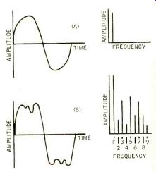
Fig. 2. A pure tone compared with the same note blown on a clarinet.
It is this special distribution of overtones that gives each instrument
its specific sound.
++++++
AUDIO ETC.

Edward Tatnall Canby
THE DOLBY
LAST OCTOBER AND NOVEMBER the British audio and record magazines were full of a new device, made in England by an American engineer, called the Dolby S/N Stretcher, a Teddy British title that is about as meaningless at first glance as you can imagine.
Now the Dolby--as I will call it--has hit America. And I expect it will turn out to be one of the most fundamental improvements in the way of noise reduction in audio systems; for that is what it does. Especially in hi-fi professional tape recording.
The Dolby is pro, strictly for the trade and not the home. (Home users will get its results indirectly in terms of better records.) This system is, to be sure, "just one more" compressor-expander circuit and it might, so it seems, sound bad.
Circuits of this general sort have been appearing for many years and with many a claim and many a fussy over-ingenuity.
For good sound, most of us tend to distrust them like murder.
But this one is really different. This one works. It goes straight to one of the most difficult of today's residual hi-fi recording problems low-level noise.
Principally, for us, in tape recording.
But also in many other areas not my concern: motion pictures, video tape, mastering and dubbing (this is part of the recording process ... ), land transmission lines and--for all I can figure--broadcasting, telemetry, a hundred areas where noise at low levels is a problem. Let's talk only about recording on tape. That's plenty.
I was sent the Dolby literature and specs some time ago, as were many editors and engineers. Most of the recipients, I suspect, took one look and put the info aside for later study-then forgot. I did myself. But luckily for me, the inventor, Mr. Ray M. Dolby, phoned up unexpectedly one day in New York.
We talked for a half hour and the upshot was that I went back for a closer look at the literature. Glad I did.
Not long after, I ran straight into the Dolby itself, large as life. It was in actual use, first-in- America, by one of our enterprising independent recordists, Marc Aubort (Elite Recordings), who had just completed some tapes with it for the Nonesch label. I was supposed to be listening to Rachmaninoff and Kodaly and Handel on the tapes, with a view to the musical annotations which I was to write for Nonesuch. (That's my other self.) Instead, I ended up talking Dolby like crazy--and listening.
I heard two tapes, one made straight from the mikes and the other, same performance, put through the Dolby on recording and playback. Astonishing.
This thing has its cake and eats it, let me tell you! It didn't do anything wrong.
To the best of my ear, it did everything right. That's what Aubort thought too.
An amazingly effective noise reducer, and-as Marc explained to me (and Dolby in his literature) a lot more, too.
This thing goes on working far into the future. It catches things like print through as they occur, methodically reducing them, whenever the Dolby tapes are played back.
To give you basic specs in a few words, the Dolby lowers effective low-level noise content in tape playback (our immediate concern) by 10 dB and more, down in the crucial low end of the dynamic range where the really bothersome noise is found. It reduces tape hiss, modulation noise, stereo crosstalk, high-speed flutter or "scrape" and, most especially, PRINT-THROUGH, all by this major factor of 10 dB-plus, as compared to the signal itself. And this without introducing any measurable distortion o/ any kind into the signal-proper, which remains unchanged in all respects.
So they say. So I heard.
Overshoots and Undershoots Oh yeah? You don't believe it. Never heard of any kind of insertion gadget that didn't do something unpleasant to signal quality? More intruded circuitry? NO! And in particular, a dynamic compression-expansion system-definitely not that! Leave our hi-fi alone. Let's have a clean signal and forget the noise. It's extremely low-level, isn't it? Why fuss? For too many years we've known all about the nasty side effects of compression and expansion circuitry, the overshoots and undershoots, the swishes and the hush-hushes, the ringing and sneezing sounds, the multiple types of distortion therein implied, not to mention plain degradation of signal as it goes through much too much circuitry. And not to mention, also, the falsities in the sound itself, the musical distortions of space and distance which are perpetrated by many such circuits-enough to have put me well off them a long time back.
(Compression makes the music recede in space as it gets louder, the space itself seeming to grow smaller; expansion brings the music rushing forward on climaxes, the hall size suddenly much bigger.) Let's limit compression-expansion, then, to extreme necessities. Like broadcasts from Vietnam. Or sports comments from baseball sidelines. We're talking about hi-fi.
Nevertheless, the Dolby. more lengthily entitled the Dolby A301 Audio Noise Reduction System and costing a couple of thousands (two systems for stereo) does compress during its initial phase (before recording in our case) and expands, to match, in the second phase (playback). Yet the darned thing really does not seem to have any effect at all on signal quality. I heard it. It just reduces noise, and that by a major degree of audibility. Hard to believe.
Excellence
Many factors, of course, are involved in this. There's first the solid-state circuitry, with 9 silicon transistors and 138 semiconductor diodes-count 'em if you dare. That, plus generally high quality and highly intelligent design (so I would gather) contributes a vital element, rock stable exactitude of values of a sort impossible with tubes. The Dolby unit has no controls whatsoever. It doesn't need them. It never changes. Its values are fixed And exact. Believe it or not.
Then there is excellence of fidelity.
The over-all noise level is "better than 80 dB (unweighted) below peak operating level" and the over-all total harmonic distortion is less than two tenths of a percentile at the same very low levels surely unusual in transistor circuitry if I am right-this from 30 Hz to 20 kHz.
(Ugh, don't like. 30 to 20,000 sounds so much more convincing ...) This being a dual unit, there are similar readings in the way of internal crosstalk between the two, down in that 80 dB range again. And there are maximum advantages, reasonably new in this area, that accrue from the low-impedance operation throughout. Also advantages thanks to "special control signal rectifying , and smoothing techniques," by means of which Dolby achieves "both very low distortion at low frequencies and a very fast response time ... aspects which are mutually exclusive in normal time-constant circuits." Those are Dolby's words for you. Strong words.
Near the Mud General excellence, and let the engineers argue as to the details; they go beyond my official engineering know-how, if not beyond my intuitive sense of what looks good and what doesn't. What struck me at once, though, was a more important single innovation that is crucial in the Dolby as compared to other compression-expansion circuits an aspect that instantly persuaded me that this gadget, of all gadgets, just had to work for recording.
This compressor-expander, you see, operates only down in the very lowest signal levels, down near the mud. It compresses ONLY the faintest components of the ingoing signal, boosting them from almost nothing to a bit more than almost nothing. Then, in the precisely equalized output, it pushes this tiny sound component back where it was in the first place. With it, pushed down into nothingness, goes all the additional noise that may have been added after the fact, after the original Dolbyizing of the signal.
Get the idea? This is, of course, a two-stage operation. Dolbyizing and de-Dolbyizing. Two units in one. They are the same; you may strap them for either function, in or out. First you Dolbyize your signal, boosting the lowest levels of sound 10 dB before recording. Then, on playback, you de-Dolbyize, restoring all the original levels exactly. (Yep, exactly.) And reducing whatever noise has been added in the meantime by the recording (or other) system.
You see, if this complex circuitry operates only on the lowest levels of sound, then the rest of the signal is left as is.
The main body of your sound is neither "distorted or affected in any way whatever," as Dolby so positively puts it.
What low levels? Very low levels, and thereby lies a trick of tricks. For it is at the bottom level that we now find our most deadly noise problems-and the better we get, the worsé these tiny residual noises seem, thanks to the incredible sensitivity of the ear for extreme lowlevel sound.
That's the rub, all right. The more noise we remove, the more clearly we hear what is left. Down to that Ivory pure 99 44,/ 100th percent--in terms of sound power. It shouts, that residue.
Masking
Enter here the masking effect, that sublime and helpful phenomenon which counteracts our undue ear sensitivity.
Thank the Lord for masking! Loud sounds mask out lesser sounds, which are unheard even though still measurably present. Dolby uses masking, like everybody else. As soon as signal level is high enough to mask the residual noises, they disappear. Since they are extremely tiny-if very obtrusive, all by themselves, the masking effect covers all but those annoying instants of near-silence, down near the mud. That's where noise shows.
But masking is tricky, as many an engineer has found to his disgust. Masking goes by frequency. You can't easily mask a low tone by a louder high tone.
It even goes by wave-shape or content.
A speaking voice can be understood against a musical sound at the same level. Indeed, the whole area of apparent effect in masking is of the utmost subtlety and complexity. So what matters here is not that Dolby uses masking in his automatic adjustment to dynamic sound levels, but that the specific aspects of the automatic adjustment are workably and rightly calculated. That's where the man shines! Get to that in a moment; but go back to the over-all fact that this compresser-expander works only at the lowest levels. That makes it already a likely bet. For, you see, it takes enormous advantage of our acute hearing down in the tiny, infinitesimal bottom range, down where the print-through and the tape hiss live, where our persnickety ears are grossly annoyed by micro-sounds that won't even make a meter pointer move a millionth of a millimeter. Deal with those and you deal BIG, with physically tiny signals. Maximum advantage, for minimum outlay.
Down there, we're dealing with the good old human ear in its own coinage.
So the ear "exaggerates" these unwanted mini-noises, like print-through and tape hiss? OK, we'll exaggerate them right back. We'll get in there 'way down and do something selectively where it matters. Leave the macro-sound alone. It's not the problem. Push down the mini sound in its own bailiwick. By 10 dB and more.
You see, if this circuit really works as intended, something good is bound to happen. It's aimed precisely at the heart of the problem-tiny unwanted sounds with a big relative impact.
Exactitude
Now, after this slightly roundabout approach, let's look closer. Two vital elements of the Dolby system impress me further in detail. First-the exactitude of the equalization, the compression and its matching re-expansion. Via older tube circuits, there would be inevitable trouble right here, due to an inexact match. Non-linear trouble. Worse, that non-linearity would vary from unit to unit despite the best of designing and worst of all, it would vary in time, as old fashioned components usually do.
To maintain any sort of exact standard, there would have to be constant adjustments, check-ups, alignments and what have you. And controls. That sort of variableness simply cannot be introduced into top-quality recording circuitry--we have enough trouble as it is, thanks.
How can Dolby dare add another set of possible variables? It's just plain unthinkable.
Well, Dolby answers persuasively. First, of course, is that low-level business. His pre-shaping and re-shaping of signal applies only to the faintest low-level area.
No heavyweight compression or expansion-no overloads due to an expanded macro-signal, nor any of the ills that the grosser kinds of compression usually bring. The Dolby treatment is, so to speak, dainty and delicate. Just a touch of treatment, at precisely the right place.
The main signal virtually unaffected.
But even so the Dolby in-and-out match itself really does appear to be extraordinarily exact, and extraordinarily permanent. Modern technology, solid-state, at work. It can he done. It is done, here. How else would he have the nerve to produce identical units minus all controls? And at a professional level, mind you.
The standard Dolby match, he says, "is straightforward, being accomplished simply by connecting networks identical with those used for recording in the feedback loop of an amplifier. In this way all steady-state and transient effects are automatically taken into account and the output signal becomes identical with the input signal in all respects." No two ways about that. And, furthermore, he says, "this can be proved with an oscilloscope and sine waves, square waves, impulses, and keyed wave forms, as well as by the most critical A-B listening tests using any type of program material." He really puts it on the line.
He's asking for it.
Seeing is believing via a good scope and known input signals. So is hearing, via a good A-B type ear. That's the instrument I used and it said "excellent!". The piano square waves, for instance, those violently sudden initial transients, were totally unchanged and wholly natural after Dolbyizing and de-Dolbyizing.
I heard no trace of signal degradation.
The "in" and the "out" matched as claimed, and the improvement in terms of noise reduction was astonishing, even with the best low-noise tape and top grade equipment. The "out" signal, to put it plainly, sounded like what you hear directly through the mikes. That's precisely the idea.
So confident is Dolby of all these parameters of performance that all his units, and all the tapes made with them, are claimed to be permanently interchangeable. Any tape, any Dolby unit anywhere, anytime. That's the vital point for the recording industry and he had better be right! Any Dolby tape may be equalized out, i.e., played back on any Dolby equipped system. Tapes may be interchanged, inter-spliced, dubbed at any time, new or old. (Phase response, by the way, is not a significant factor, again being equalized out.) You may Dolbyize (stretch) and de-Dolbyize a signal over and over again in successive copies, too, and the net distortion is almost entirely that of the output amplifiers, cumulatively less than two tenths per cent per copy; the noise addition, of course, keeps getting removed time after time. (Hence the usefulness of the Dolby in dubbing operations.) Independent Suspension There's still the second big technical feature to describe. Granted the Dolby system is inherently stable, uniform. precise, and interchangeable, that it affects only the lowest sound levels-what else? Plenty. Dolby's circuitry does not (as did the original and well remembered H. H. Scott noise suppressor circuits of late 78 days) vary the frequency band pass. Nor does it operate a macro-compression and expansion of large segments of signal. To meet the peculiar phenomenon of low-level sound masking by the ear at its own exact terms, Dolby has hit a circuit jackpot. He operates in four separate bandwidths, to cover the major areas of noise without interaction between bands. In other words--here we have a kind of four-way independent suspension, like a Volkswagen.
Each band (down in the ultra-low levels, remember) compresses and expands independently: in the hum-and rumble range (these are Dolby's terms), in the mid-audio range, in the medium high frequencies (that would be the troublesome and controversial "presence range," wouldn't it?) and in the high frequencies. A high signal level within any one of these bands will not prevent noise reduction in the other bands wherever the signal may be low.
Boy, is that tricky! No swishes and hush-hush effects. Each sound-type given its own treatment, and no unpleasant interactions. It can't be that simple? Well, at macro-levels it might not work so well. But at the low Dolby micro-levels, I guarantee you, it does work. Just like a Volkswagen works. Reliable too.
Inestimable Distinction
Now finally, let's get to practicalities.
You may need to do a bit of quick double-take thinking here. I did. You can't make something out of nothing.
You can't, for instance, treat a tape that is already made. Except to copy it with a minimum of added noise-which is a very valuable feature, by the way, since tape copying is done by the mile in every recording company, and every dubbing adds more noise and general degradation.
(By dubbing through the Dolby you "convert" an older tape into a Dolby tape, using the tape playback as the "original." Any noise already on that tape will be dutifully preserved in the copy. But new noise will thereafter be minimized.) The Dolby noise reduction affects only those signals which are added after the initial Dolby treatment. In recording it is done before the tape-recorder input, right at the recording session. Just plug into the input circuit. Everything that is wanted goes through the Dolby first--and then is recorded. The tape machine doesn't know the difference, of course. It takes down the Dolbyized signal (boosted 10 dB or more in each of the four low-level bandwidths) as so much gospel.
Later on, it plays back the same, as well as it can. Then the playback signal is put through the second Dolby unit, which knows exactly what it is doing.
All elements of the original that were boosted up are now pushed back down to normal. But all added noises (low level) are pushed that much below normal, not having had the inestimable distinction of having been boosted by Dolby in the first place.
I'm moved to think in terms of convention delegates. Maybe at a sports-car convention. Or even a hi-fi show. The Dolby pre-emphasis of the separate bands of low-level signal is like the convention badge you pin on your lapel, to boost your big ego. It doesn't really change you very much (you being the bulk of wanted signal . . .) but it does let you through the mighty gates with wallet intact and personality un-dented, when the showdown comes. (Playback.) Whereas other people, minus badge, un-boosted (the added outside noise components . . .) are pushed down, reduced, robbed of their cash and their ego. Get. it?? (OK forget it.) , Space is used up. Between now and next month I expect a lot of recording executives, big and little, will be tearing their hair and investigating Dolby right and left. I don't think Dolby has a U.S. address yet; but you can get the literature from Dolby Laboratories (Laboratries), 590 Wandsworth Road, London, S.W. 8, England. Or call somebody and find out what's happened since I wrote this.
By next month, these gentry won't need any more comment from me. But for the rest of youse, I'll expatiate then on what the Dolby can mean in specific terms for the future of the recording industry. It could mean very nearly a revolution in many ways. I suspect.
+++++++++++++++++
LETTERS
DEAR SIR: I am thinking of updating my equipment. I have $500 to spend. What would you suggest as the best way to spend my money.
SIR: I want to get a modern receiver and before I spend my money, I would appreciate your advice. Should I buy ***, * * *, or * * * in the $300 to $500 range.
SIR: My present speakers are now more than ten years old. My ears tell me that many current models provide superior performance to what I now have. I am restricted to the bookshelf-sized models and a price of around $100 each per unit. Could you suggest what is likely to be the best value in this group? (These letters are perhaps characteristic of the many we receive each month of those for which there are no ready answers. We cannot recommend specific equipment. We really cannot test each new piece of equipment, nor do we hear every new product under conditions that favor an accurate impression.
We do get to most of the new high-fidelity component shows so it could be said that we are in a position to see and hear much of what is new. This is, on the surface, true. But the impressions gained at these expositions are incomplete-we cannot form honest opinions from them. As an example: we have at shows often heard speakers that sound poor under the influence of local acoustics only to find that this was a false impression when we hear the speakers some other time.
There are many such examples. For this reason alone we cannot recommend specific instruments. And if this is not reason enough, think of this. Much equipment is purchased on the basis of purely subjective analysis. How can we responsibly suggest to a stranger what he will like? We can go on and on. But the message here is simple. We cannot respond to requests for specific product recommendation. This should not be construed to indicate that we are unresponsive to requests for information we can respond to. Quite the contrary. We welcome your letters and promise to answer all: either in this column or directly. En. ) The Authoritative Word (This letter was received regarding E.T.C.'s explanation of the word Seraphim.) SIR: Seraphim is a plural word. In the Hebrew language, the letters "im" are added to masculine nouns to form the plural. Cherubim ditto. Angelim, no. It's charming, but it's not kosher.
MRS. EVA KAPLAN, Physics Librarian, The Weizmann Institute of Science Rehovoth, Israel
DEAR SIR: I wish to take this opportunity to thank you for your extremely comprehensive and accurate Tape Recorder guide in the December issue of AUDIO Magazine.
It has been called to our attention that our listing incorporates an error in the wow and flutter column in each of these issues. Specifically the wow and flutter figure at 7 1/2 ips, is listed at 0.9% on all models, in reality this is 0.09%. This may have been a copying error, or the information originally supplied by me may be in error.
Incidentally, the large picture of the four-channel 800 in your December issue is very impressive. I do hope that the customer is not confused or mislead into thinking that this is a standard SS 822 or SS-824 model; in reality it is of course an SS-844 four-channel recorder.
JOHN W. HAINES, Customer Service, Crown International, Elkhart, Indiana
DEAR SIR:
Compliments on the December Tape Recorder Compendium. However, the price shown for two of our Magnecord models was as wrong as wrong can be.
The 1022 and 1028 models are shown at $1788.00 and $1995.00 respectively.
This is exactly $1,000 too much. The correct prices are, of course, $788 for the 1022 and $995 for the 1028.
JAMES S. ARRINGTON, Magnecord Div. Telex Corp. Minneapolis, Minn.
(What can we say after we say oops. Ed.)
+++++++++++++++++
EDITOR'S REVIEW
CONTINUAL PROGRESS
IF THERE IS ONE CHARACTERISTIC for which the high fidelity industry is noted, it is change. Over the history of AUDIO, we have seen triode tubes in output stages, then pentodes, then tetrodes, then the Ultra-Linear circuitry which makes tetrodes perform more like triodes, and now most new models are entirely transistorized, including the output stages. More recently, the FET has made considerable headway, with several makes employing them, and the next forward step is likely to be integrated circuits, some of them already having made their appearance. Aside from their saving in space, it is claimed that their performance can improve the over-all performance of the equipment in which they are used. We certainly expect to see more of them in the future.
We made no mention of nuvistors or hybrid types of circuits, for in general they appeared to be a transitional step from all-vacuum-tube operation to all transistor circuits. It took some time to make a good front end with transistors, and some fairly sophisticated transistors to make them work as well as we had taken for granted as normal for tube equipment.
Without getting into the argument as to whether tubes or transistors are better, we can only surmise that the transistor is here to stay. There is certainly a difference of opinion among users as to which is the better. Letters from readers often seem to be most vociferous in their praise of one or another of the tube amplifiers, and an equal dislike for transistors.
Yet many are strongly in favor of transistors. Our only suggestion is that each person make up his own mind. As between triode tubes and tetrodes, there was always a dispute, yet it is well recognized that there were (and are) good amplifiers of both types, and that discussion has never been resolved. Similarly, there are good amplifiers using tubes and good ones using transistors. You takes yer choice.
We have always faced the same difference of opinion about loudspeakers and enclosures. It has always been our position that the ultimate user is going to listen to his system and that someone else couldn't possibly tell him which was the best. Each person's own ears must help him decide. There is enough good equipment of all types to provide a choice. We honestly do not believe that one type is necessarily better than another-there are good and bad examples of all types. Our recommendation is that a comparison of specifications should be the guide to an intelligent selection. All other things being equal, the listening test is then the final step in making a selection. If you can afford an amplifier in the 0.05-percent-distortion class, and if you like the way it sounds, then by all means, buy it. If you don't like the way it sounds, don't buy it under any conditions.
BUCKNELL IS A UNIVERSITY
In our story about the Bucknell student who has been a hi-fi enthusiast for six years, we referred to Bucknell as a college and of course, were reminded that it is a University. Now if we were to say we didn't know there was a difference, we would be called to task for that. We do know the theoretical difference which is something like the difference between a ship and a boat. We learned that during a short sojourn on a Navy vessel some twenty years ago-a boat is something that is carried on a ship.
And while we are on the subject, we want to credit Thomas Trout as the "professor in hi-fi" to the young man pictured on our January cover, who described Mr. Trout in that fashion. Wonder how many other AUDIO readers have served in a similar capacity to their neophyte friends.
PASSING OF AN ORACLE
We were saddened to learn of the death of one whose work has long been regarded as of inestimable value to the audio buff. Fritz Langford-Smith, author of the "Radio Designer's Handbook" recently passed away in Sydney. Australia, at the age of 62. The first edition of this book, although only some 375 pages in length, devoted considerable space to audio circuitry, and was probably the most used audio reference book of its time. The massive third edition was practically an Audio Handbook in itself, and all of us will miss future editions. It is not likely that another such encyclopedic volume will be attempted, in spite of the great need for one.
GAG OF THE MONTH
Did you hear about the audio buff who complained, "Here I just spent over $700 for a new hi-fi outfit and they start using megaphones again."
+++++++++++++
Tape Guide

by HERMAN BURSTEIN
If you have a problem or question on tape recording, write to Mr. Herman Burstein at AUDIO, 134 North Thirteenth Street, Philadelphia, Pa. 19107. Please enclose a stamped, self-addressed envelope. All letters are answered.
Q. My tape recorder has a signal-to-noise rating of 38 dB based on "normal maximum record level." A similar machine of another make claims a ratio of 56 dB. Can there be this much difference, or how may I reconcile the two claims?
A. The answer depends on how much distortion is produced when your machine is operating at "normal maximum record level." I might guess that the distortion is 1 per cent, in which case the signal-to-noise ratio would be about 44 to 46 dB with reference to a recording level that produces 3 percent distortion.
I get this by adding 6 to 8 dB to the 38-dB rating. However, if "normal maximum record level" produces less or more than 1 per cent harmonic distortion, then the signal-to-noise ratio (referred to 3 per cent distortion) would be respectively greater or less than 44 to 46 dB.
Q. Several months ago I recorded some discs on tape at 3.75 ips, quarter track stereo. After about seven months of playing, these tapes, of double-length polyester, started giving me trouble. I can hear the tracks adjacent to the ones I am playing. I think this is called reverse channel spillover. If this is due to misalignment of the heads, why don't I have the same problem with tapes of conventional thickness? If the trouble is misalignment, can I realign the heads myself? A. If you are experiencing "spillover" only with thin tapes, it may be that the extraneous sound is not the reverse channel but is print-through of adjacent layers of tape. The thinner the tape, the greater the print-through. Also, print through increases with storage time, so that it may be unnoticeable immediately after recording but quite noticeable later on.
To align your heads vertically, you can use either an alignment tape or a substance called Magna-See which enables you to see the recorded track on a tape and thereby tell whether the track spans the proper part of the tape.
However, moving the head vertically may impair the azimuth alignment, and accordingly you will also need an azimuth alignment tape. I think your best course is to have a competent tape recorder service agency check the vertical alignment.
Q. I am looking for a circuit for a "transistor line transformer" to feed a 50- or 250-ohm mike output into a 50K or 100K high impedance input. This circuit would use a silicon planar transistor and would have to be equal to or superior to the finest mike transformers available. Enclosed is u circuit from a C.E. Transistor Manual. I have constructed two of these but have found that with 40 to 50 feet of mike cable the r.f. and hum pick-up are intolerable (the circuit shows an unbalanced-two terminal-input). Can you suggest a high-quality, no-compromise circuit?
A. Circuit design is outside the scope of the TAPE GUDIE column, and I don't have the temerity to try to improve on a G.E. circuit. However, I am not sure that the answer to your problem lies in a better impedance conversion circuit. First, one may question the wisdom of circumventing a microphone input transformer.
The transformer permits you to balance out hum through a balanced line connection (center tap of the transformer primary is connected to ground). It is quite possible for a high-quality transformer to give you as good frequency response and as low distortion as your transistor circuit. In other words, i am questioning the idea of transistorization for it's own sake.
Second, your manner of connecting the microphone to the transistor circuit may be accounting for excessive hum and r.f. pick-up. I suggest that you try all possible ways of connecting the microphone shield cable: to one of the hot microphone leads; to the other hot lead; grounded at the transistor circuit end; not grounded at the transistor circuit end; and so on. Make sure that the shield is grounded to the microphone casing.
Q. For the purpose of braking the supply and takeup reels, is it feasible to stop the motors by changing the a.c. to d.c., instead of using mechanical braking? I have heard that this is done. What type of motors are used, and how is it done?
A. The current general practice is to use mechanical braking. However, I understand that in the past some machines have used electrical braking as you describe, and that a very few still do. I believe that a d.c. voltage from about 24 volts upward is momentarily applied to the motors. If this voltage is applied too long, the motor will begin to smell and may burn out. The d.c. is obtained by rectifying the output of one of the secondary windings of the power transformer and using a dropping resistor of appropriate value. I do not have information on specific circuitry or motors suitable for this method of braking. You might look through manuals of tape recorder schematics until you come across a machine that uses d.c. braking.
Q. Recently I received a Wollensak half-track stereo tape recorder. I would like, however, to take advantage of the many quarter-track tapes on the market. Specifically, my questions are:
1. Nortronics makes a half-track to quarter-track replacement kit for my machine. Could 1 bypass the electronics in my machine and use the tape-head inputs of my audio amplifier? This would permit me to use the speakers of my audio system instead of the tape machine's speaker.
2. Are there any small recording amplifiers that I can use to record stereo? My machine cannot presently record stereo.
A. If your external amplifier has inputs specifically intended for tape playback heads, you should be able to make a direct connection from your quarter track stereo head directly to the amplifier without undue difficulty. Use as short a shielded cable as feasible, route it carefully away from sources of hum such as motors and transformers, and make sure the cable has relatively low capacitance (about 25 to 30 uF per foot). For recording purposes, today there are relatively few makes of tape electronics that you can purchase separately.
Consult Nortronics as to what they make. They do have circuit information sheets. Also check the catalogs of mail order houses such as Allied Radio and Lafayette. I doubt that you will find electronics purely for recording; the electronics will probably have provision for both recording and playback. It will be necessary for you to make appropriate adjustments in this electronics, using the controls provided, for bias current, for recording current, for erase current, and for record-level indication. While the manufacturer of the tape electronics will of course supply instructions for making these adjustments, it is often necessary to have instruments in order to achieve optimum performance.
Q. I have two tape recorders. When a tape recorded on one machine is played on the other, the resulting sound is fuzz..' (distorted), and there is a definite loss of highs. Tape sounds fine when played on the same machine used for recording. I assume this is due to different azimuth positions of each machine's playback head. I have a VTVM, 'scope, and audio generator. So I can make a test tape on one of the machines, which has separate record and playback heads, and adjust the playback head on that machine and on the second machine for maximum output. What frequency shall I use on the test tape? With this procedure, everything is adjusted to the record head on one of my machines. How can l be sure this is OK, since commercial tapes will be played?
A. The proper procedure is to use a commercial test tape having an azimuth alignment tone in the range of 10,000 to 15,000 Hz. 15,000 Hz is preferable. In the case of your three-head machine, align the playback head for maximum output when playing the test tape. Then simultaneously record and play a 15,000 Hz tone, and adjust the record head for maximum output in playback. In the case of your two-head machine, simply adjust the record-playback head for maximum output when playing the test tape.
I don't know whether correct azimuth alignment will remove your distortion problem. It is conceivable that poor motion (flutter) is producing distortion, but tends to cancel out when a tape is played on the same machine on which it was recorded.
Q. Regarding comparative measurements of tape noise, I recently saw a reference to "third-octave noise." Can you tell me what this means, or refer me to some literature? Also, are tape noise figures commonly stated on an unweighted or weighted basis?
A. In some measurements of the noise of a tape or tape machine, it is desired to ascertain how noise varies with frequency. Measurements are taken of noise at selected bandwidths, so that one-third of an octave is measured at a time.
An illustration of such procedure appears in "A New Magnetic Tape with Greater Dynamic Range," Preprint No. 290 of the Audio Engineering Society, Box 383, Madison Square Station, New York, N. Y. (price 85c). Noise figures for tape machines are commonly stated on an unweighted basis.
However, the human ear is more sensitive to high-frequency noise than to mid and low-frequency noise, whereas a good meter will give equal weight to all noise frequencies. Therefore in order to obtain measured results which accord with subjective results, a high-pass filter is sometimes employed to remove the obscuring effects of hum and other low frequencies.
+++++++++++++
Sound and Sight
HAROLD D WEILER
While many different methods may be employed to analyze, adjust, and evaluate the various components employed in video recording and closed-circuit television systems, the examination of a properly lighted test pattern, such as that illustrated in Fig. 1, displayed on a standard video monitor of known quality, is probably the simplest and most effective for general purposes.
These two devices will provide a quick and accurate means of determining overall performance, comparing equipment, checking and making adjustments, and diagnosing many of the problems which may be encountered in video components and installations. Problems in bandwidth, over-all frequency response (r.f., i.f., and video), phase shift (streaking), shading and contrast of horizontal and vertical signals, as well as focus, centering, aspect ratio, linearity, and distortion can all be interpreted from a test pattern.
A test pattern of the type shown may be obtained from the Electronic Industries Association in Washington, D.C. When a high-quality monitor of the type shown in Fig. 2 is employed, any deviation from the normal pattern may be caused by the camera, the transmission system (coaxial cable and/or connectors), the video recorder, or the monitoring equipment employed in the installation. To be certain that this test system is always capable of providing a visual facsimile of the actual signal on the transmission line the monitor employed as a standard should be periodically checked with a high-quality video camera.
If you are to employ successfully the combination of a test pattern and a standard monitor for signal analysis, evaluation and diagnosis you should be familiar with the appearance of an unimpaired video signal. You should also know the various deviations from the normal image created by camera mis adjustment or defects, problems in the transmission system, video recorder or in the display monitors included in the installation.
When inserted into a system which is operating perfectly, the standard video monitor should display a test pattern similar to the original. The pattern illustrated is free of discernable defects as indicated by the fact that circles are round, straight lines are straight and that there is a complete range of ten individual gradations of shading between the black and white picture elements.
The first step, in employing this test system is proper "set-up." The test pattern should be mounted on a wall, the camera on a tripod. Both should be in such a manner that the pattern can be centered on and perpendicular to a line through the camera lens axis. The exact distance between the test pattern and the camera is dependent upon the focal length of the lens employed and the physical size of the test pattern itself.
Most vidicon cameras used in video recording and closed-circuit television, today, employ a lens with a focal length of 25 mm. for general purpose applications. In this event the correct distance between the test pattern and the focus ring of the camera lens is approximatelydouble the measured width of the test pattern. The lens focus ring should be set at the actual measured distance between the pattern and the focus ring for the best resolution. The test pattern should be illuminated by a 100-watt lamp in a reflector, mounted about five feet from the test pattern (behind the camera). The camera, equipment under test, and the standard monitor should be allowed to warm up for at least five minutes to ensure stability. The camera should then be moved slightly closer to or further from the test pattern so that the picture limits (the small white wedges at the borders of the pattern), just touch the edges of the monitor tube mask. The camera and other equipment controls should then be adjusted to provide an optimum picture as described in the individual manufacturer's instruction books.
The first test usually made when evaluating or adjusting video equipment is to determine resolution. The resolution of equipment determines the amount of discernable detail displayed in the picture. A picture which is sharp and clear and on which minute details are easily discernable has good or high resolution. When the picture is blurred, soft, and the smaller details are indistinct, it is said to have poor or low resolution.
Most scenes in addition to the brightness gradations in a horizontal direction also have brightness gradations in a vertical direction. In consequence, the overall picture quality is dependent upon a combination of the amount of resolvable detail from the top to the bottom of the picture, which is called the vertical resolution, and the resolvable detail from the left to the right side of the picture which is termed the horizontal resolution.
Vertical resolution is primarily dependent upon the size and shape of the pick-up and reproducing-tube scanning beams and is fundamentally limited by the number of horizontal lines scanned.
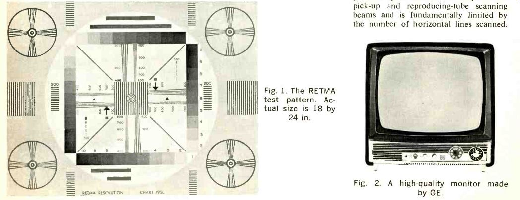
Fig. 1. The RETMA test pattern. Actual size is 18 by 24 in. ; and Fig. 2. A high-quality monitor made by GE.
The United States Television Standard, established in 1941, which is the standard in commercial TV broadcasting and most educational and industrial television applications, limits the horizontal scanning line rate to 525 lines. Once this line rate was established, the vertical resolution, in those services where it is employed, is limited to approximately 350 lines.
Vertical resolution is usually expressed in the number of distinct horizontal lines, alternately black and white, which can be perceived in a test pattern. The horizontal wedges, indicated as (A) in Fig. 1, are employed for this purpose. These wedges each consist of two groups of four individual converging lines. The vertical resolution is determined by locating the point at which the individual lines are no longer separately visible and then reading the calibration figure adjacent to that point. For example, were we to check a high quality video camera, operating at the standard 525-line rate, we would find the individual lines on the horizontal wedges would merge and become indistinct in the vicinity of point (B) in Fig. 1 indicating that the vertical resolution was approximately 350 lines.
In some of the more sophisticated closed-circuit television systems employed by science and industry there are no restrictions on the horizontal line rate, in consequence the vertical resolution can be increased substantially providing much finer detail than can be obtained with the horizontal scanning rate of 525 lines.
Horizontal scanning rates as high as 1023 lines are being employed in these installations. These are capable of a vertical resolution of over double the broadcast resolution or 715 lines and in consequence provide a considerably more detailed picture.
Table 1 illustrates some of the horizontal line rates employed today and the vertical resolution which can be obtained through their use.
TABLE 1.

Horizontal Line Rate
Vertical Resolution
525 350 625 440 675 470 837 585 875 610 945 660 1023 715
This article will be continued next month to provide additional information on the use of a test pattern to evaluate, analyze, and adjust video equipment.
++++++++++++++++++
ADs:
-----------------------
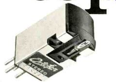
EXPERTS AGREE ... ORTOFON S-15T Stereo Cartridge is rated tops.
Don't take their word for it, be your own judge.
Hearing is believing. Before writing for literature, listen to it at your Franchised Dealer.
ELPA MARKETING INDUSTRIES, INC., Dept. 11 A3 New Hyde Park, N.Y. 11040
------------------
This is our idea of a well rounded speaker. Empre's The Royal Grenadier 9000
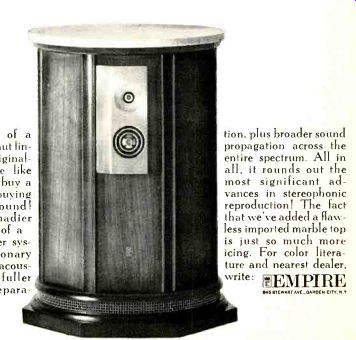
Forget the frills of a hand-rubbed walnut finish, statuesque originality and language like that! When you buy a speaker, you're buying performance. Sound! The Royal Grenadier 9000 is our idea of a true-to-life speaker system. Its revolutionary die-cast divergent acoustic lens assures fuller frequency and separation, plus broader sound propagation across the entire spectrum. All in all, it rounds out the most significant advances in stereophonic reproduction! The fact that we've added a flawless imported marble top is just so much more icing. For color literature and nearest dealer, write: EMPIRE , Garden City, N.Y USA.
+++++++++
A Young Upstart creates a new concept in sound systems.
THE RECTILINEAR III is specific ally engineered to eliminate one of the major failings o quality dynamic speaker systems,-narrow band frequency response, commonly referred to as "BOX SOUND".
There is absolutely no boom which makes for reproduction of organ pedal tones and other such program material with free sounding NATURALNESS rarely encountered in the art o speaker design.
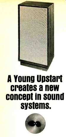
THE RECTILINEAR III is a no compromise reproducer. Its wide linear frequency response and dispersion characteristics are indicative of the meticulous engineering that has produced this innovation in speaker de sign. We believe that our system is so superior that an actual AB comparison will support our claims.
RECTILINEAR III. $234.50. Size: 35"H x 18"W x 12"D. Hand Rubbed Oiled Walnut. Frequency Response: 22-18,500 Hz +/-4 db. Impedance: 8 ohms. Detailed Specifications available upon written request. Listen to it at better dealers or write, Rectilinear Sound Systems A development of Rectilinear Research Corp. 7116 20th Ave., Brooklyn, N.Y. 11204, usa.
+++++++++
AR speakers
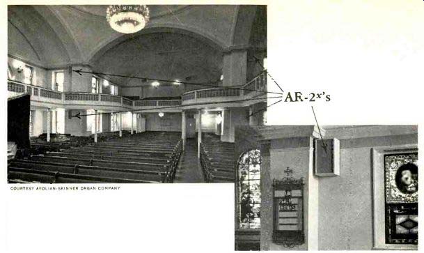
COURTESY AEOLIAN-SKINNER ORGAN COMPANY.
The AR-2x loudspeakers marked by arrows--there are 16 in all are part of a synthetic reverberation system installed by the Aeolian-Skinner Organ Company in St. John's Episcopal Church, Washington, D. C. This system corrects building acoustics that are too "dead" for music. Listeners are not even aware of the speakers (which simulate normal hall reflections), since the sound of the organ and chorus is completely natural. AR speakers were chosen by Aeolian Skinner for this and other installations because of the need for full range, undistorted bass, absence of false coloration, and reliability.
AR inc. SPEAKERS ARE USED PROFESSIONALLY WHERE LIVE MUSIC IS THE IMMEDIATE REFERENCE--BUT THEY WERE DESIGNED FOR THE HOME.
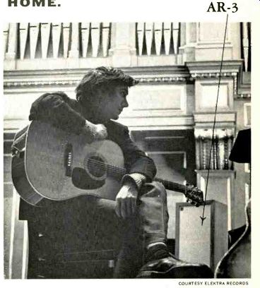
Folk singer Phil Ochs,
sitting on the stage of Boston's Jordan Hall, checks Elektra's master
tape for a concert album he has recorded there. COURTESY ELEKTRA
RECORDS.
The tape will become Elektra record EKS-7310, (mono EKL-310) "Phil Ochs in Concert." The artist and recording staff must listen for technical as well as musical quality, and therefore require loudspeakers that provide the most natural sound possible no bass where there shouldn't be any, no "speaker sound." AR 3's are used.
AR speakers are $51 to $225. A catalog of AR products-speakers and turntables-will be sent free on request.
AR-3.
ACOUSTIC RESEARCH, INC., 24 THORNDIKE STREET, CAMBRIDGE, MASSACHUSETTS 02141
+++++++++
Try this on your changer.
1.5 grams (one record); 1.5 grams (stack of eight)
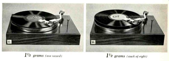
The arm of the AR turntable is designed for neutral balance, so that stylus force doesn't change as the cartridge rides up and down the surface of a warped record. The needle doesn't alternately dig into and lose contact with the groove.
Keeping stylus force the same at different cartridge heights is even more important in changers. The stylus force on the eighth record should be the same as on the first.
In some units it is 50% higher, but it doesn't need to be. We do not believe that automatics are inherently inferior to manuals. It is just that for the same quality they are inherently more expensive. They should be judged by equally high standards, with particular attention paid to whether they maintain constant stylus force and constant speed as records build up on the platter.* About 4% of recorded selections take up more than one disc; whether you use a changer or a manual turntable the remaining 96% must be turned over by hand. A changer has a real advantage only if a good part of your listening is to the multi-record albums, or if you like to stack unrelated singles.
The AR turntable meets NAB standards for broadcast turntables in rumble, wow, flutter, and speed accuracy. It has been rated as being the least sensitive to mechanical shock of all turntables, and has been selected by professional equipment reviewers** above all other turntables, including those costing twice as much. The price is $78 with arm, oiled walnut base, and transparent dust cover.
*We will be glad to send you a reprint of the article "What the Consumer Should Know about Record Players," describing how the layman can check these characteristics in the home.
Please ask for it specifically.
**Lists of the top equipment choices of four magazines are available on request.
All four chose the AR turntable. (Three of the four, incidentally, chose AR-3 speakers.)
ACOUSTIC RESEARCH, INC., 24 THORNDIKE STREET, CAMBRIDGE, MASSACHUSETTS 02141
+++++++++++++++++
+++++++++
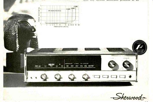
Compare these new Sherwood S-8600 features and specs!
ALL-SILICON reliability. Noise-threshold-gated automatic FM Stereo/mono switching, FM stereo light, zero-center tuning meter, FM interchannel hush adjustment, Front-panel mono/stereo switch and stereo headphone jack, Rocker-action switches for tape monitor, noise filter, main and remote speakers disconnect.
Music power 140 watts (4 ohms) @1 0.6% harm distortion. IM distortion 0.1% @ 10 watts or less. Power bandwidth 12-35,000 cps. Phono sens. 1.8 mv. Hum and noise (phono)-70 db. FM sens. (IHF) 1.6µv for 30 db quieting. FM signal-to-noise: 70 db.
Capture ratio: 2.2 db. Drift .01%. 42 Silicon transistors plus 14 Silicon diodes and rectifiers. Size: 16 3/4 x 4 3/4 x14 in. deep.
WE HAVE COME TO EXPECT HIGH PERFORMANCE FROM SHERWOOD and ... the S-8800 did not let us down.
POWER OUTPUT . S-8800. 140-watt FM ALL-SILICON Receiver
$359.50 for custom mounting
$368.50 in walnut leatherette case
$387.50 in hand-rubbed walnut cabinet
The tuner section, with its high sensitivity and very low distortion, is among the best in the business-clean and responsive. FM Stereo comes in loud and clear and, as the curves plotted at CBS Labs show, with very ample separation. The usual increase in distortion, when switching from mono to stereo in receivers, was in this set just about negligible. We would say that Sherwood has come up here with another typically 'hot' front end that makes FM listening a sheer joy.
"As for the amplifier ... comparing the results with the specifications, it is apparent that the S-8800 does provide the power it claims, and this-for a popularly priced combination set-is considerable. A glance at the IM curves, for instance, shows how much power the S-8800 will furnish before it runs into any serious distortion problem at all three impedances.... For rated power bandwidth distortion of 1%, the curve ran below and above the normal 20 to 20 kHz band; and the 1-watt frequency response was virtually a straight line in this area, being down by 2.5db at 40 kHz-fine figures for a receiver .. . "Those heavy percussion and crisp castanets will come through with just about all the con brio the performers have put into them.
As appeared in HIGH FIDELITY Magazine Equipment Reports by CBS Labs. November 1966 issue.
3-YEAR WARRANTY
Sherwood Electronic Laboratories, Inc., 4300 North California Avenue, Chicago, Illinois 60618. Write Dept. 3A
+++++++++
Also see: