MANUFACTURERS SPECIFICATIONS
Ranges: 40, 80, 160, 320, 640, 1,280, 2,500, 5000, 10,000, 15,000 and 20.000 Hz. Lift and cut: plus or minus 16 dB, or plus or minus 8 dB. Slope: 12 dB per octave. Input impedance: 100 k ohms. Output Impedance: 200 ohms. Frequency response: plus or minus 0.25 dB. 20 to 20 kHz. Maximum output: 7 volts. Distortion: IM and THD less than 0.1% at 2.5 volts output. Hum and noise: 90 dB. Dimensions: 17 inches wide by 7 inches deep and 5.25” high. Price $450.
The only thing equalizers, as a family of equipment, have in common is that they all operate on the frequency response of the signal passing through them. At one extreme we have the garden variety of tone controls which shape the frequency spectrum broadly and coarsely. While on the other extreme there are equalizers which can control a narrow band of just a few Hertz in calibrated decibel steps. Some equalizers give boost as well as loss to the passing signal; others just loss.
Some work in one particular region, serving a special purpose, while others operate throughout the audio frequency spectrum with varying degrees of frequency resolution. For sound reproduction, the narrowest band useable is 1/3 octave wide because the 'ear doesn't resolve anything much narrower. The broadest we want are regular tone controls.
There are three good reasons and two bad ones for using equalizers:
1. to change the program material; 2. to change the frequency response of the audio system; 3. to compensate for the absorption inequities created by room acoustics; 4. to compensate for loudspeaker deficiencies; and 5. to compensate for hearing loss.
Reason No. 1 is a good reason to use equalizers because individual taste as to what constitutes correct or proper balance between musical sounds can now be exercised when desired.
While in most cases we prefer to let the recording team do their thing by dictating frequency balance, sometimes things get out of whack by the time their creation gets reduced to disc, tape, or tape cassette, and is about to be played. Reason No. 2 is a good reason because it is so very difficult to obtain flat frequency response in a system, advertising claims to the contrary, notwithstanding. Reason No. 3 is also a good reason because equalizers can eliminate unavoidable imperfections of our listening environment to a large extent. Reason No. 4 is a bad reason and one which is often misunderstood. If a loudspeaker system rolls off at 50 Hz, it means it is incapable of operating below that region. Boosting the input to the loudspeaker below this frequency will distort the sound. If it were not so, all the loudspeaker manufacturers would have to do is reduce the efficiency of the upper frequency range drivers and we would thereby get more bass by driving the loudspeakers harder. It is fair to assume that loudspeaker manufacturers have already considered the limitations of their designs and optimized the frequency response of their product--at least as far as the frequency extremes are concerned. It is possible to boost the extremes somewhat if the loudspeaker has high power handling capability and we don't play it at its loudest. Compensation for the loudspeaker's inaccuracy in the mid-range is also tricky because it can cause ringing and play havoc with its transient response.
Finally, Reason No. 5 is a good reason because it we compensate for a known ear deficiency, during listening to music at home, who will compensate the orchestra during listening to live music? After all, to the ear, regardless of deficiency, the live orchestra is the reference. To compensate for this deficiency during playback only, will therefore disorient the listener when he's hearing the real live thing. The use of equalizers is fascinating, but like most good things, fraught with danger. Equalizers need to be used with discretion that comes from learning how to use them. Used well, equalizers can significantly improve the perception by most listeners of reproduced sound. Misused, however, equalizers can ruin the balance beyond recognition, mislead diagnosis of a system malfunction and damage loudspeakers.
The SAE Mark Seven Stereo Octave Equalizer, as it is called, is the best stereo program equalizer for home use that we've so far come across. Since the equalization is done in octave bands and both stereo channels are acted upon with one lever, the unit is intended and best used as a program equalizer, explained above as Reason No. 1. It might possibly be used for the second reason, but for the third-not so well. Reason No. 1 is enough, however, since the Mark Seven does this superbly. Having been thoughtfully designed and skillfully assembled, the equalizer is a natural to use and after five minutes of diddling with the smoothly gliding levers, one never wants regular tone controls again.
Fig. 2---Showing filter coils on a circuit board mounted behind the front panel. The active electronic circuits and power supply are mounted on boards visible in the rear.
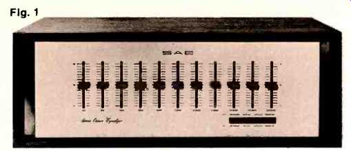
There are ten filters with center frequencies one octave apart, starting at 40 Hz, and an eleventh one at 20,000 Hz, which is a half octave above the tenth at 15,000 Hz. 30,000 Hz would have been wasteful. Four push-buttons at the lower right corner control the operating modes. Besides the on/off and bypass controls expected, there is a range-halving control plus a tape monitor switch. See Figure 1. The range selection increases resolution of the control while the tape monitor button replaces the one on the preamp, which must now be engaged if the Mark Seven is connected in the tape loop. An alternate connection is to put it between the preamplifier and the power amplifier. For use with receivers and integrated amplifiers, however, it must go into the tape loop. That is, it receives its input from the receiver's recorder output signal and injects its output into the receiver's tape play or monitor high level input. The four stereo pairs of phono jacks at the equalizer's rear panel facilitate hook-up.
The control levers glide past eight graduations above the detented center position and eight graduations down. Each mark represents one or two dB, depending on whether the range-halving push-button is depressed or left in its out position. There is no on-off indicator, which sort of understates the equalizer's effect. In time, equalizers such as this one will augment systems so proudly that nothing short of blinking lights will seem appropriate. Or looked at differently, the only way to achieve incognito participation will be to hide it under the table. The highly pleasing appearance and cushioned feel of the curved attenuator lever knobs of the Mark Seven say that the unit be proudly displayed.
Each lever, which has a long throw of 24", controls a filter network centered around the frequency, silk-screened onto the anodized brushed aluminum chassis. The circuit utilizes coils, capacitors, and resistors, resonating at the eleven specified frequencies. Transistors are used before and after the filters for impedance and gain matching.
The filter circuits are all mounted on a large printed circuit card close behind the sliding potentiometers, as shown in Figure 2. The front filters circuits are far away from the rear mounted electronics, which probably accounts for the phenomenally low amount of noise introduced into the system by this device.
Figure 3 shows the Mark Seven's response to input signals from 30 Hz to 20,000 Hz, as plotted on a graphic level recorder automatically coupled to an audio oscillator. The line is the effect of the unit with all controls in their neutral position.
There is a slight roll-off below 1000 Hz, and an overall loss of 1 dB between input and output. The two curves show the response at the lever extremes, showing the action of the controls. Since there are so many possible combinations of filter lever positions, we've chosen a representative few for the graphs. Figure 4 and 5 show several such settings and gives an idea of the unit's tremendous equalization capabilities.
Figure 6 and was indistinguishable from the input waveform.
Its response to square waves fared no worse, as shown in Figure 7. Figure 8 shows the effect of increasing degrees of boost at 2 dB intervals, per the panel markings. The maximum input voltage that the unit could handle before clipping, when its filter controls were all set to maximum, was 1.5 volts rms. With levers flat, it can take 10 volts in. With levers set for average use, it will handle up to 5 volts without distortion.
Maximum output of the unit is 10 volts, which is more than any amplifier needs.
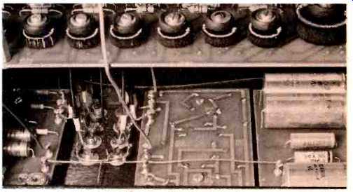
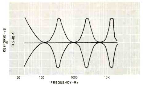
Fig. 3-The upper curve was obtained by placing controls 1, 4, 7, and 10 at maximum with the rest at center. The lower curve was obtained with controls 1, 4, 7, and 10 at minimum and the rest at center. The line is a neutral setting.
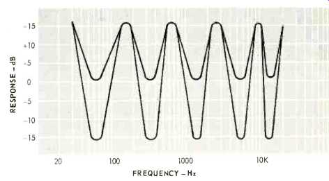
Fig. 4-The upper curve shows results of placing controls in alternate maximum and center positions; the lower curve shows response with controls at maximum and minimum settings.
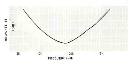
Fig. 5-This curve represents extreme compensation of low and high frequencies.
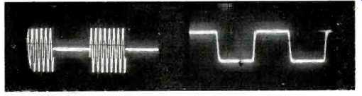
Fig. 6-Tone burst response at 1500 Hz.

Fig. 7-Response to 10 kHz square wave.
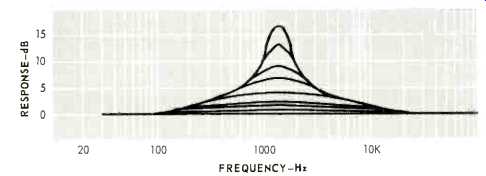
Fig. 8-Showing the narrowing effect of the pass band at increasing degrees
of boost. Each curve was plotted with the 1280 Hz filter raised by two dB.
We were unable to measure harmonic or IM distortion within its normal operating range, that is, both are below .05%. Signal to noise with all controls flat was measured at 93 dB and with controls in an average compensating configuration, 83 dB. What these figures mean is that used with discretion, the Mark Seven is a virtually distortionless device.
We connected the unit to a high quality stereo system already equalized for the listening room with 1/3 octave equalizers. Playing various types of records and tapes, we switched the preamp's tone controls out of the circuit and played with the Mark Seven equalizer controls. After a little practice, we were able to adjust it without even looking at the controls. It sort of became intuitive and definitely improved some of the records. We then took the 1/3 octave room equalizer out of the circuit and attempted to compensate for the room with the SAE unit. We first tried by ear, then used the pink noise calibrated microphone technique.
In both cases, and as we expected, we achieved only limited results for two reasons. First, the two channels require different compensation which the Mark Seven has combined; and second, one octave resolution is too coarse for correcting room modes. So we went back to using it as a program equalizer, which is its intended purpose. With this capability we were able to correct for such common recording defects as overly bright brass, wiry strings, and deficient fundamental bass. To cymbals, we were able to add sheen which somehow had gotten lost.
The SAE Mark Seven Stereo Equalizer will find a fitting place in any elaborate audio system. and while not inexpensive, will certainly make its presence heard. Pun intended.
The Mark Seven is also useful for the serious recordist who wants to salvage tapes that were made under adverse conditions or somehow went sour in the process. It can thus serve in post-recording equalization.
-A.R.
(Audio magazine, mar 1971)
Also see:
SAE A202 Amplifier (Jul. 1987)
SAE Model 2922 Integrated Amplifier (Mar. 1979)
SAE Mk XII Speaker System (May 1973)
SAE Model 5000 Impulse Noise Reduction System (June 1977)
Robertson Sixty Ten Amplifier (Jan. 1986)
= = = =