MANUFACTURER'S SPECIFICATIONS:
THD (To rated output): 0.01 percent.
IMD: Any two mixed frequencies from 20 Hz to 20 kHz, 4:1, 0.01 percent.
Rated Output: 2.5 V.
Frequency Response: Phono, RIAA ±0.25 dB; Line, 20 Hz to kHz, ±0,25 dB.
S/N Ratio: Phono re: 10 mV input, "A" weighted, 90 dB; Line re: 2.5 V out, "A" weighted, 110 dB.
Phono Overload: 150 mV.
Phono Input Termination: 47k and 100 pF.
Phono Gain (To tape out): 35 dB; 60 dB to pre out.
Gain (Line input): 25 dB.
Power Amplifier Section:
Power Output: 100 watts continuous per channel from 20 Hz to 20 kHz, 8 or 4 ohm loads.
Rated THD: 0.05 percent.
Rated IMD: 0.05 percent.
S/N Ratio: 100 dB below rated output.
Square Wave Rise Time: 2.5 microseconds.
Slew Rate: 40 V/ uS.
Damping Factor: 150 at 100 Hz.
Input Sensitivity: 1.5 V rms.
Price: $850.00.
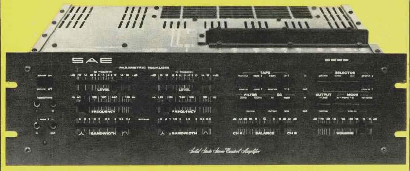
We've all heard it said that an integrated amplifier is really nothing more than a power amplifier and a preamplifier assembled on one chassis. In the case of SAE's Model 2922 that is almost literally true. SAE calls this unit a preamp/amp, rather than an integrated amplifier, and the reason is obvious when one looks at the unit. They have taken their Model 2200 power amplifier (which carries a price of $500.00) and "attached it" to their Model 2900 Parametric Equalizer/ Preamplifier (which is also designed to sell for $500.00). By eliminating a couple of frills such as the peak-power LEDs of the 2200 and assembling everything that's left on a single, large chassis, the resulting 2922 comes out costing considerably less than the sum of its parts. All of the signal handling circuitry of the 2922 is identical to that used in the equivalent separate units. In fact, the shape of the chassis is a sort of dead giveaway.
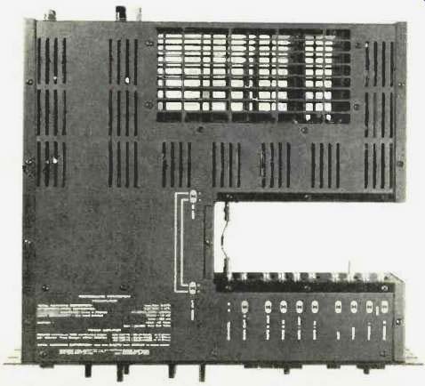
The rear power amplifier section is "attached" to the front preamp section by a sort of "bridge" at the left, but remains separated from it at the right to form a U-shaped recess as one looks down on the unit from the top. Input and output cables relating to the preamp are connected within this open U-shaped area, while speaker outputs and A.C. connections are on the rear of the amplifier section as one would normally expect. Short pin-to-pin cables interconnect the preamp outputs to the main amp inputs, just as if the two were separate units.
The front panel of the SAE 2922 is black, like other SAE products, and has no rotary controls or switches whatever.
All functions are controlled either by pushbuttons or slide levers. At the left is a power on/off button and just below it are twin stereophone jacks plus Tape 2 in-and-out jacks which permit connection of a tape deck via the front panel.
The left side of the panel also contains six continuously adjustable slide controls, arranged in two groups of three each, which take care of the parametric equalization functions of the preamp-control unit.
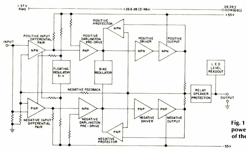
Fig. 1--Block diagram of the power amplifier section of the SAE 2922.
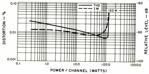
Fig. 2-Power output vs. distortion with 8-ohm loads at 1 kHz.
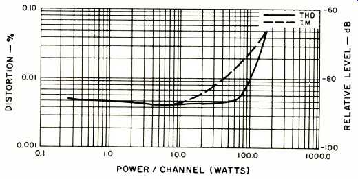
Fig. 3- Power output vs. distortion with 4-ohm loads at 1 kHz.
As most readers probably know by now, a parametric equalizer provides three degrees of response control. Instead of simply varying the degree of boost or cut at some specified center frequency (as is the case with graphic equalizers), the controls on a parametric equalizer let you adjust the center frequency to be boosted or cut, as well as the bandwidth or "Q" of the resonant circuit associated with each frequency band to be controlled. Because of this increased degree of flexibility, fewer frequency bands or sets of controls are required with a parametric equalizer. Some separate parametric equalizers provide three, four, or five bands or sets of controls. The SAE 2922 offers only two, but each covers a wide range of center frequencies. The low-frequency control can place the desired center frequency at any point from below 40 Hz to 1.2 kHz, while the high-frequency control varies center frequencies from 1.2 to 16 kHz. As much as 16 dB of boost or cut can therefore be applied at any two desired center frequencies selected by the user. The bandwidth controls adjust the shape of the boost or cut curve from 0.3 octaves to 3.6 octaves.
Two slide controls at the lower right of the panel are used for channel balancing and master volume control. Above the balance control are four pushbuttons, two of which activate the low-cut filters, while the other two turn on the EQ and provide for pre- or post-equalization at the tape outputs as required. Above these buttons are four more which select tape monitoring and dubbing or copying functions. The number of possible combinations using these eight buttons is staggering. The owner's manual describes 21 possible combinations of dubbing, copying, monitoring, and assignment of equalization, and provides simple-to-understand diagrams and flow charts to help the user become familiar with all the possibilities available.
Two more rows of four pushbuttons each are located above the volume control slider. The upper row takes care of program selection (phono 1, phono 2, tuner and AUX), while the lower four buttons select various modes of output (including 12 dB audio muting) such as left-mono, right-mono, stereo, and reverse.
As we mentioned earlier, input connections are made in the U-shaped area which separates the preamp and amplifier sections of the chassis. Two sets of outputs are supplied, so even with the preamp outputs connected to the associated amp section, one could drive a second, remote power amp by connecting to the alternate output pair.
Circuit Highlights of the Power Amp Section
As can be seen from the block diagram of Fig. 1, the circuitry of the SAE 2922 power amplifier section is totally complementary from input to output. This is made possible by the 55V use of dual-complementary differential input stages which are followed by the full complementary push-pull predriver stages. All stages up to this point are operated in Class A. The drivers drive a full complementary output stage. This output design, according to SAE, results in high current capability without loss of power bandwidth, a high slew rate, and low leakage current.
Bias current in the output stage is controlled by a compound transistor regulator circuit. SAE takes the position that d.c. amplifier coupling is undesirable and uses a.c. input coupling instead. However, the low-frequency cutoff point is set at an ultra low 0.01 Hz. Four triple-diffused output transistors and four driver devices are used. SAE states that output stage capability is so great that the amplifier will de liver rated power into any load, whether resistive or reactive.
The amplifier is also equipped with relay protection circuitry which not only protects loudspeakers from possible dam age but also protects itself under severe load conditions. A thermal cutout is employed to protect against high tempera ture operation. In addition, a low-impedance electronic sensing circuit limits output current with loads below 2 ohms without in any way limiting current for loads of 4 ohms or higher, or when the amplifier is used with highly reactive loads such as electrostatic speaker systems.
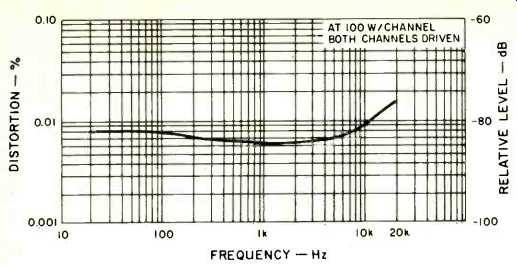
Fig. 4--Distortion vs. frequency with 8-ohm loads.
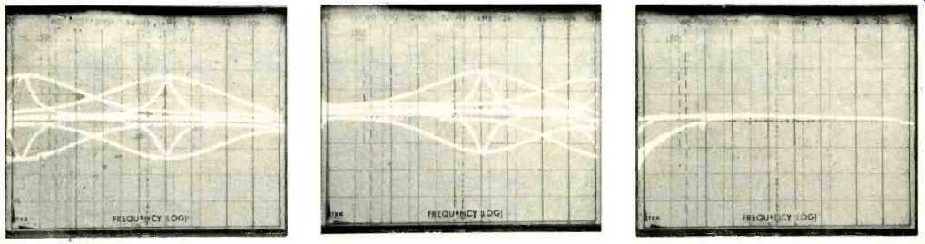
Fig. 5--Range of frequency, bandwidth, and amplitude adjustment for the
low frequency section of the parametric equalizer.
Fig. 6--Range of frequency, bandwidth, and amplitude adjustment for the high frequency section of the parametric equalizer.
Fig. 7--Response of the low-cut filters.
Power Amplifier Measurements
We measured available power output at 1 kHz for both 4-ohm and 8-ohm loads, since SAE rates the 2922 for both of these load impedances. With 8 ohm resistive loads, the amplifier delivered 120 watts per channel, both channels driven, before reaching it rated THD and IM distortion levels of 0.05 percent. At rated output, THD measured only 0.0065 percent while IMD measured 0.015 percent. Results of our power-vs-distortion measurements are shown in Fig. 2, for 8-ohm loads, while in Fig. 3 we have plotted the same information for 4-ohm resistive loads. In 4-ohm operation, the amplifier delivered 156 watts per channel at 1 kHz, but of course, continued operation at such high power levels would result in thermal shutdown because of high current levels drawn, hence the more conservative rating of 100 watts, even for 4-ohm operation.
Figure 4 is a plot of harmonic distortion versus frequency for 100 watts of constant output level, both channels driven into 8-ohm loads. Even at 20 Hz, THD remained a very low 0.008 percent, while at the 20-kHz high frequency extreme, it measured 0.015 percent. Damping factor was measured at 50 Hz, rather than at the 100 Hz specified (50 Hz is the required frequency at which this is measured in accordance with the new IHF Amplifier Measurement Standards), and obtained a relatively high reading of 112. Full rated power at rated distortion was available over a frequency band from 16 Hz to 26 kHz. Dynamic headroom measured exactly 1.0 dB.
The slew rate of 40 volts per microsecond was confirmed as was the square-wave rise time, which, in our tests, actually measured a bit better than claimed, 2.0 microseconds. The amplifier consumed approximately 80 watts under no-signal conditions, with power consumption increasing to slightly more than 500 watts when driven to rated output into 4-ohm loads.
Preamplifier/Control Section Measurements
RIAA equalization of the phono input stages was accurate to within +0.5 and-0.2 dB from 20 Hz to 20 kHz. Input sensitivity in phono (referred to 1.0-W output) measured 0.17 millivolts, while 8 mV was required to drive the amplifier to a 1.0 watt output level via the high level inputs. Phono overload at 1 kHz measured a very high 200 mV. Frequency response via the high level inputs from input to amplifier output was flat from 4 Hz to 6Q kHz, -1.0 dB, and from 3 Hz to 120 kHz,-3.0 dB. Signal-to-noise ratio in phono (measured with a 5-mV input and with amplifier gain control set to deliver 1-watt output) measured 70 dB ("A" weighted), while for high-level inputs, S/N (measured with a 0.5 V input and gain adjusted to produce 1.0 watt output) measured 77 dB, "A" weighted.
Operation of the two sets of parametric equalizer controls can best be understood by referring to Figs. 5 and 6. The multiple plots displayed on the face of the frequency-calibrated log-sweep 'scope in Fig. 5 show the entire range of control possible with the three low-frequency parametric equalizer slide controls. As claimed, the center frequency can be shifted from below 40 Hz to just above 1 kHz, and bandwidth affected by these controls can also be varied over a wide range, as shown.
Action of the high-frequency parametric equalizer control set precisely overlaps that of the low-frequency controls, be ginning as it does with a center frequency of just above 1 kHz which can be varied up to around 20 kHz. In experimenting with these controls we discovered that if both the low and high frequency controls are set to 1.2 kHz, the action of the two sets of controls is cumulative and one could, theoretically, achieve a boost or cut at that particular frequency of more than 30 dB. (That's hardly a practical setting, but of interest nevertheless).
The 'scope photo of Fig. 7 shows the response of the low cut filters which are set to 30 Hz and 100 Hz. By depressing both of these filter buttons at once, it is also possible to obtain a somewhat steeper sloped cut-off below 100 Hz as shown by the lowest response curve in the photo.
Listening and Use Tests
I, personally, have always liked the sound of SAE amplifier and preamplifier products, and the SAE 2922 is no exception.
While I confess that SAE's reasons for staying away from fully d.c. coupled designs don't seem entirely justified to me in view of present-day design philosophies, I must confess that I could not hear any form of sound degradation that might be attributed to that a.c. coupled input, even when I listened to the power amplifier alone and bypassed the preamp section. On the contrary, sound was tight, well defined, and transients were reproduced effortlessly and with no smearing whatever.
If you haven't worked with a parametric equalizer before, you'll find that they take some getting used to. My own feeling is that if you are going to go with parametric equalization because your system really needs it (either in terms of room problems or speaker problems), you may find that limiting the number of bands to only two could pose problems. On the other hand, compared with even the most elaborate "bass and treble" tone control arrangement (however augmented they are with selectable turnover frequencies, etc.), even this two-band parametric equalizer system wins by a mile. SAE should have no problem selling this honestly de signed and ruggedly built integrated amplifier (or preamp amplifier, if you insist on using their terminology). If it causes any problem at all for SAE, that problem is more likely to be how to continue to sell the separate 2900 and 2200 models upon which this design is based. I guess they will have to rely upon the fact that some people have very shallow shelves.
-Leonard Feldman
(Audio magazine, Mar. 1979)
Also see:
SAE Model 5000 Impulse Noise Reduction System (June 1977)
= = = =