By Dipl.ing . Werner Fidi [Director, Research and Development, AKG, Vienna; With English text by Geoffrey M. Langdon, Technical Manager, AKG, Philips Audio Video Systems Corp., Mahwah, N.J. ]
DISCUSSIONS about phono-cartridge design often center around the pros and cons of various transducer types. However, regardless of the electrical generating principle used in a phono cartridge (moving magnet, moving coil, variable reluctance, etc.), all designs have in common the need for a mechanical moving system or stylus assemble.
Serving to couple the movement of the stylus tip to the generating element, the moving system is at the very heart of a cartridge's "personality." Any flaws or non-linearities in this system or its transfer characteristics become part of the cartridge's final output. No matter how good the design of the generating system (or any other part of the listening system), it cannot correct or remove any ill effects of the moving-system's design and construction.
Although choice of generating principle has secondary effects upon the parameters of the moving system, we will limit discussion in this paper to the design considerations directly involving the moving system.
One of the first and best known goals is a moving system with a minimum of equivalent mass. Choice of generating principle (moving-iron) was made with this and numerous other considerations in mind. However, minimum equivalent mass, alone, is far from the complete design concept for a moving system of high quality.
The Traditional Moving System
The construction of a typical stylus assembly is illustrated in Fig. 1. It consists of a diamond stylus (a), an aluminum cantilever tube (typically 5 to 6 mm long, and 1 mm in diameter) (b), and an iron tube (c). These three elements are rigidly connected to each other, forming the stylus assembly which, in turn, is elastically suspended at an appropriate point.

Fig. 1--Typical stylus assembly; a is diamond stylus, b aluminum cantilever
tube, c iron tube, d wire suspension, e carrier, and f rubber damping element.
Conventional stylus suspensions are fabricated by connecting a thin wire (d) near the pivot point of the stylus, fixed to the suspension carrier at the other end (e). For purposes of damping, some type of rubber element (f) is usually used. Result: The moving system.
In stereo recordings, each wall of the record groove is modulated independently, at 45 degrees to the vertical axis of symmetry. This modulation applies signal-dependent forces to the stylus tip which can lead to transverse motion in any direction. It is important that the translation of this modulation into electrical signals remain even and independent of direction of stylus motion over the full audio spectrum. In other words, the moving system should be capable of omnidirectional response without introducing frequency-dependent amplitude or phase distortion. This is a necessary requirement if correct and stable stereo imaging is to be maintained.
Analysis of the moving forces acting on the stylus assembly, as well as of all elastic and frictional moments (Fig. 2), reveals an interesting phenomenon: the pivot point of the stylus assembly actually shifts along the axis of the cantilever at higher audio frequencies. This results from the fact that, at these frequencies, the inertial forces of the moving system significantly counteract the forces of the suspension system. Uneven frequency response, insufficient channel separation, unstable stereo imaging, and poor tracking ability result from this "wandering" pivot point.
The following points evolved as requirements for an optimal suspension design:
1. Universal symmetry with respect to transverse (side-to side) movements.
2. A single-point bearing (pivot point).
3. Maintenance of control parameters by all frictional and elastic moments in all directions of transverse excitation.
4. Suppression of torsional and axial moments.
5. Resonance-free suspension and proper damping of the stylus assembly.
6. Components with extra strength and resistance to aging, and with superior stability under varying climatic conditions.
7. Ease of production and uniformity from unit to unit.
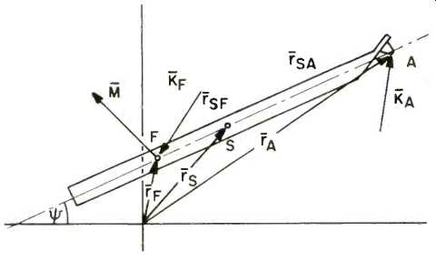
Fig. 2--Analysis of moving forces of stylus assembly.
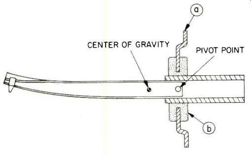
Fig. 3--Construction of AKG Transversal Suspension System.

Fig. 4--Distribution of restoring and damping forces versus distance from
the pivot point for a conventional moving system and AKG Transversal Suspension
System.
The Transversal Suspension
The solution to the pivot problem is relatively simple: a single-suspension element comprises both the spring (suspension and restoring force) and frictional (damping) functions. This results in a pivot point "drift zone" which is limited to a small, practical dimension. The tracking force of the cartridge is transferred to the stylus tip through torque forces created at the suspension element. To be more specific, as the stylus tip rests in the record groove, the cantilever will swing up at the stylus end until the torque-generated force reaches equilibrium with the tracking force. By minimizing the length of the lever over which this torque is generated, the chance of dynamic shifting of the pivot point is greatly reduced. Further, placing the plane of the suspension force perpendicular to the cantilever axis and directly through the pivot point concentrates all forces essentially at one point. In conventional designs, the plane of the suspension force (wire) is parallel to the cantilever, and therefore, not clearly defined as a single-point force.
Figure 3 illustrates the construction of the Transversal Suspension System. The cantilever is centered symmetrically in a small hole in a very thin, gold-plated metal plate (a). The hole is only marginally larger in diameter than is the cantilever assembly. The plate and the gold-plated cantilever assembly are connected to each other by a newly developed rubber element (b) which is vulcanized to both metal parts via a special process. The gauge of the suspension plate is quite small in comparison to the diameter of the cantilever assembly. The result is a knife-edge bearing of incredibly small size. When transverse force is applied to the stylus, the cantilever assembly "rolls" back and forth over the knife-edge. Due to the design's complete symmetry, the same mechanical conditions exist for transverse excitation in all directions. Essentially attributable to the extremely small distance between the cantilever assembly and the edge of the hole, the knife-edge effect virtually eliminates dynamic shifting of the pivot point. Variation of the shape of the rubber element allows control of the dynamic forces and torque distribution free from any effects on the pivot point.
Figure 4 shows the distribution of restoring (R) and damping (D) forces versus distance from the pivot point for both a conventional moving system and the Transversal System. A distinct advantage of the Transversal System is that the effect of the rubber element upon restoring force (compliance) decreases quite rapidly with distance from the pivot point, while a definite contribution to its effect upon damping is to be found at extended distances. Independent control of these two forces may thus be accomplished. By tailoring the shape of the rubber element, or by combining two rubber elements, it is possible to control the damping. If two rubber elements are used, a hard rubber may be used in the vicinity of the pivot point (where forces are large) while a softer rubber may be used at greater distances for damping control.
This has the advantage of maintaining the desired firm, small, fixed pivot point. It also provides the softer material necessary for damping at a position which prevents any negative effects on the critical pivot and support functions, and where it is free from large static suspension forces. This eliminates one of the basic reasons for inclusion of the support or tie-back wire characteristic of traditional designs: hysteresis or sagging of the soft rubber element due to the large static suspension (tracking) forces.
In Summary
The moving system operates "omni-directionally" in the transverse plane as a result of symmetrical construction and the "knife-edge" technique. Damping is controlled independently of other functions, greatly casing a traditional compromise situation and providing resonance-free performance without sacrificing other parameters. Torsional and axial pulling forces and thrusts are controlled by the minute distance between the suspension plate and the stylus cantilever, and by using a harder rubber suspension element than previously possible. The harder element also ensures robustness, thermal stability, and a high resistance to aging and hysteresis (permanent deformation) effects. All these contribute to a new standard of performance accuracy for stereophonic and matrix-quadraphonic image delineation and stability.
Also see:
Birth of a Spec? PHONO CARTRIDGE NOISE (March 1977)
= = = =