Manufacturer's Specifications
Power Output: 1 00 watts/channel into 8- or 4-ohm loads, 1 75 watts/channel into 2-ohm loads, 75 watts/channel into 16-ohm loads; in mono bridged mode, 200 watts/channel into 4- or 8-ohm loads.
THD: Less than 0.03 percent, 4 and 8 ohms; less than 0.05 percent, 2 ohms.
Dynamic Headroom: 3 dB at 8 ohms, 2 dB at 2 ohms.
Reactive Load Rating: 3 dB.
Capacitive Load Rating: To 0.8 µF.
Frequency Response: 10 Hz to 30 kHz, +0,-0.25 dB.
Input Sensitivity: 90 mV for 1-watt out put.
Input Impedance: 50 kilohms in parallel with 300 pF.
SMPTE-IM: Less than 0.01 percent.
IHF-IM: Less than 0.01 percent.
TIM: Less than residual in test equipment of 0.006 percent.
Slew Factor: Greater than 10.
S/N: 80 dB below 1 watt (110 dB be low rated output).
Dimensions: 3.12 in. (79.25 mm) H x 16.9 in. (429.26 mm) W x 10.19 in. (258.82 mm) D.
Weight: 22 lbs. (10 kg).
Price: $641.00 East, $656.00 West.
The arguments over whether or not one can hear differences between similarly rated and similarly measuring amplifiers will probably be with us for many years to come. As far as this reviewer is concerned, however, the Apt 1 Amplifier, the second product to be introduced by Tom Holman in the past couple of years, settles the argument in my mind. It sounds better than most amplifiers in its price and power class and, I might add, these judgments are not only my own but those of my listening panel of associates and friends who, as in all recent tests, had no idea what was being compared with what and whether the switch was really being thrown from A to B or from A to A or, as was true in some cases, from B to B! As well as providing superlative sound, the Apt 1 is also one of the most conservatively designed amplifiers we have encountered in some time. And in addition and unlike some amplifiers which perform well on the lab bench with idealized loads but fail to measure up sonically when delivering power into real-world loads, the Apt 1 can easily deliver its rated power, and then some, into the most complex and unusual of speaker loads yet devised by man.
For all its design innovation, the Apt 1 is a compact unit and fairly lightweight at 22 pounds (or, an even 10 kilograms, if you prefer to be metric about it). Its grey metallic front panel has no controls on its surface. The only visible items on the front panel are a tiny power-on indicator light and a small viewing area housing LED indicators. The upper pair of LEDs illuminates in green whenever a signal is being amplified by the Apt 1, switching to red when an instantaneous overload condition occurs.
The other LED illuminates when the load is mismatched to the amplifier's output, at which time the user is expected to remedy the situation with an impedance switch on the rear panel.
That rear panel is equipped with color-coded, five-way binding posts for speaker cable connection, with one pair located at each end of the panel. A small switch at panel-center can be released from its normally depressed setting for bridged mono phonic operation of the amplifier. In such a mono mode, only the L input is active. A fuse-holder housing a 4-ampere line fuse is located on the rear panel, as is the aforementioned impedance switch. The switch has two settings: 8-16 ohms stereo/16-32 ohms mono or 2-4 ohms stereo/4-8 ohms mono. As previously noted, an improper setting may be indicated by illumination of the front-panel LED indicators. Such indications may take place even if the "nominal" impedance of the speakers being used corresponds to the switch setting, since nominal speaker impedance does not always correspond to actual impedance under a given set of drive conditions for an amplifier.
Circuit Highlights
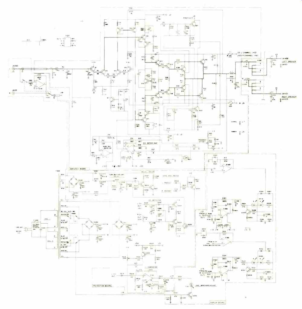
A complete schematic (one channel only) of the Apt 1 is shown in Fig. 1. The power amplifier stage employs some newly developed circuits which were conceived by Tom Holman and designer Mark Dinsmore. The first stage is a Darlington-connected differential-pair with emitter current source and gain degeneration. This configuration was apparently selected because of its relatively high stage current and attendant high slew rate combined with high input impedance and good thermal stability.
One side of the differential pair drives a current mirror, which reflects the output of half of the differential pair downwards. The second stage is driven in both directions, up and down. Each half of this stage consists of a two-transistor cascode circuit.
The output stage consists of two triple- Darlington. complementary-symmetry, common-collector stages (emitter-followers).
This configuration provides high current gain, so that load variations in impedance are reflected back to the gain stages at a very low level, with little overall effect upon the specifications of the amplifier.
The safe-area detector circuitry works much like the portion of safe area limit circuitry which detects unsafe conditions in output transistors. The detector, however, is not used to interrupt the drive to the output as it sometimes is in conventional circuits.
Instead, the detector output is used to signal the output protection relay to disconnect the load. This action is postponed for as long as possible thanks to the conservative design approach in the output-stage "safe area." Common-mode conduction from one output half through the other half is prevented from reaching destructive levels by fuses in the B+ and B- supplies to each amplifier.
Additional inputs to the relays are a turn-on delay and d.c. detectors for each channel. Since the amplifier is direct coupled internally, any input offset will appear as a larger d.c. offset at the output. To prevent such input offsets from appearing at the output, a separate servo amplifier maintains d.c. conditions at zero at the output.
A voltage/current comparator measures the V/I relationship in the left channel and drives the load impedance indicator in the event that the load impedance drops below 4 3/4 ohms in stereo or 9 1/2 ohms in mono bridging.

Fig. 1--Complete schematic, including power supply and signal/overload indicator,
of one channel

POWER / CHANNEL ( WATTS)
The power supply of the Apt 1 is unusual in that it has the ability to alter voltage and current relationships depending upon load impedance. It uses all of the power transformer regardless of the setting of the impedance switch so that windngs are not wasted in either mode of operation. B+ + and B-- voltages are developed separately from the B+ and B- voltages so as to operate the low-level stages of the power amplifier with minimal interaction with the power supply. The important driving stages are well isolated from the power output demands on the amplifier.
The dual-color LED display circuitry tests the output for small signals and lights a green LED for signal present at the output jacks. An overload detector differential amplifier triggers when ever the input and output of the amplifier do not "track" each other, This amplifier then suppresses the green LED and changes it to red to indicate overload.
Laboratory Measurements

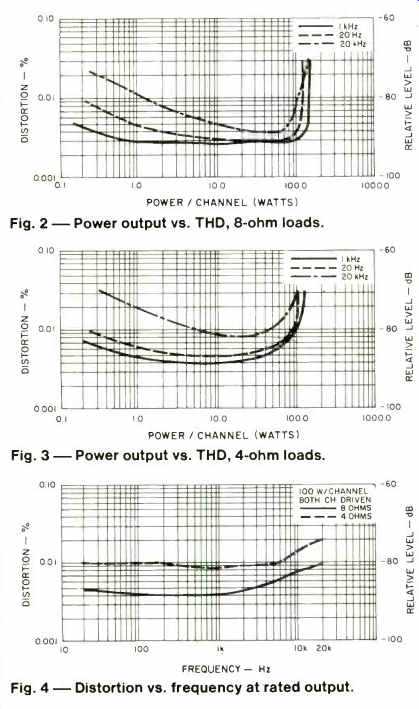
Fig. 2--Power output vs. THD, 8-ohm loads.
Fig. 3-Power output vs. THD, 4-ohm loads.
Fig. 4- Distortion vs. frequency at rated output.
With 8-ohm resistive loads connected, the amplifier delivered 123 watts per channel at mid-frequencies before harmonic distortion reached its rated value of 0.03 percent. With a 4-ohm load, power output for 0.03 percent THD was 115 watts. Re turning to 8-ohm loads, we measured a maximum continuous output of 114 watts per channel at 20 Hz and 118 watts per channel at 20 kHz. Under 4-ohm load conditions, the amplifier delivered 101 watts at 20 Hz and 102 watts per channel at 20 kHz for the same level of distortion. On the basis of the 8-ohm measurements, we would rate the amplifier as being a 114 watt per channel unit, abiding by FTC criteria, but that hardly begins to tell the whole story. This amplifier exhibited a dynamic head room of 3.2 dB at 8 ohms. That means that under music signal conditions, the amplifier can deliver short-term power peaks as high as 209 watts per channel without clipping! A plot of power output versus harmonic distortion for the 8-ohm load condition is shown in Fig. 2, while in Fig. 3 we have plotted the power output versus harmonic distortion for 4-ohm loads. Figure 4 shows a pair of plots (8 ohms and 4 ohms) of distortion versus frequency at rated output (100 watts per channel, continuous).
Power bandwidth (the frequency extremes at which full power could be delivered for rated THD, 8 ohm loads) extended from 11 Hz to 35 kHz. Frequency response at nominal power levels was flat from 3.5 Hz to 75 kHz for-1 .0 dB, extending further to 200 kHz for the-3 dB roll-off point. Damping factor was around 200 for a 50-Hz test signal referred to 8-ohm loads.
SMPTE-IM distortion measured a low 0.015 percent for rated output as against the published or rated value of 0.03 percent.
IHF-IM was so low as to be unmeasurable using our test equipment, which normally can read down to 0.01 percent. Slew factor (the highest frequency divided by 20 kHz at which full-
rated input produces an output having 1.0 percent THD) could not be measured beyond 6 on our test equipment, but we can verify that it was probably in excess of 10, as claimed, just by extrapolation. Input sensitivity corresponded exactly to the published claims, with 90 millivolts required for 1-watt output and ten times that amount needed for the rated 100 watts output into 8-ohm loads. The A-weighted signal-to-noise ratio was 88 dB below 1-watt output reference, or fully 8 dB quieter than claimed by the manufacturer.
Summary and Listening Tests
We hooked this amplifier up to a variety of speaker systems; everything from our reference KEF 105-II to some recently acquired mini-sized speakers that lack an octave or so at the bottom but are otherwise well balanced and accurate. There are those who maintain that some amplifiers do good things for certain speakers while messing up the sound of others. The Apt 1 is not such an amplifier. Each of the speaker types we tried with it seemed to benefit audibly from being driven by this superbly designed unit. Bass reproduction was extremely tight and un-muddied, and the amplifier somehow never seemed even close to running out of steam, even when coupled to relatively inefficient speaker systems. Mid-frequencies and highs were well de fined and transparent, with not the slightest hint of high-end fuzziness or raspiness under any drive conditions.
Having checked out the Apt preamplifier more than a year ago, I rather suspected that the matching amplifier would be a winner too. It is!
-Leonard Feldman
[ Orig. publ. in Audio magazine/Mar 1981]
Also see:
Apt Holman Preamplifier Two (Equip. Profile, Aug. 1985)
Apt/Holman Control Preamplifier (Equip. Profile, Feb. 1980)
Rotel RC-870 Preamp (Aug. 1985)
Amber Model 7 Tuner and Model 50b Amplifier (Aug. 1985)
Link | --Anthem Pre-1 Preamplifier (April 1997)
Arcam Delta 110 Digital Preamp (Jun. 1992)
= = = =