Manufacturer's Specifications:
Tuner, FM Section Usable Sensitivity: Mono, 11.2 d Bf.
50-dB Quieting Sensitivity: Mono, 15.2 dBf; stereo, 37.2 dBf.
S/N Ratio: Mono, 75 dB; stereo, 73 dB.
THD: Mono, 0.08% at 100 Hz and 1 kHz, 0.2% at 6 kHz; stereo, 0.1% at 100 Hz, 0.2% at 1 kHz, 0.3% at 6 kHz.
Frequency Response: 30 Hz to 15 kHz, +0,-2.0 dB.
Selectivity: 60 dB.
Capture Ratio: 1.0 dB.
AM Suppression: 58 dB.
I.f. Rejection: 110 dB.
Spurious Response Rejection: 90 dB.
Image Rejection: 70 dB.
Muting Threshold: 28.7 dBf.
Subcarrier Product Ratio: 40 dB.
Stereo Separation: 48 dB at 1 kHz, 45 dB at 100 Hz, 40 dB at 10 kHz.
Tuner, AM Section Sensitivity: 300 µV/meter.
Selectivity: 40 dB.
S/N Ratio: 50 dB.
Image Rejection: 40 dB.
I.f. Rejection: 30 dB.
Amplifier, Power Section
Maximum Rated Power at 1 kHz: 50 watts, 8 ohms; 70 watts, 6 ohms; 90 watts, 4 ohms.
THD: 0.006% at 50 watts, 8-ohm loads, 1 kHz (A-weighted).
SMPTE IM: 0.010% at 50 watts, 8-ohm loads, 1 kHz (A-weighted).
Input Sensitivity: 1.5 V at 1 kHz for 50 watts into 8 ohms.
Amplifier, Preamp Section Gain: Phono, 40.1 dB at 1 kHz, 0.5-V output; high level, 38.7 dB at 1 kHz, 0.5-V output.
Frequency Response: Phono, RIAA from 1 Hz to 100 kHz, -3.0 dB; high-level inputs, 1 Hz to 200 kHz, -3.0 dB.
S/N Ratio: Phono, 78 dB; high level, 90 dB re: 1-V input.
Subsonic Filter: -3 dB at 38 Hz, 6-dB slope/octave.
Tone Control Boost and Cut: 6 dB/octave.
Headphone Amplifier. Output: 10 mW into 8 ohms, 1 kHz; 200 mW into 300 ohms, 1 kHz.
General Specifications
Power Requirements: Amplifier, 350 watts maximum; tuner, 9 watts.
Dimensions: Amplifier, 17.5 in. (44.5 cm) W x 4.5 in. (11.4 cm) H x 12.4 in. (31.4 cm) D; tuner, 17.5 in. (44.5 cm) W x 2.5 in. (6.4 cm) H x 11.5 in. (29.3 cm) D.
Weight: Amplifier, 24 lbs. (11 kg); tuner, 81/2 lbs. (3.9 kg).
Prices: Amplifier, $699; tuner, $379.
Company Address: 218 Ridge St., Charlottesville, Va. 22901.
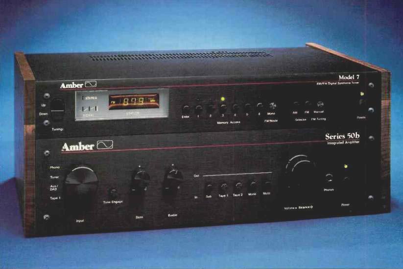
Amber Electronics has come up with a pair of components that can be purchased singly or treated as a "two piece" receiver. This tuner and integrated amplifier can, in fact, be mated to each other by making use of a pair of tall, wooden side-panels which firmly join the two components, one above the other.
The first thing that I found appealing about both pieces of equipment was the easy-to-read, white-lettered nomenclature on their black front panels. No subdued lettering or undecipherable ''international symbols" here-just good old, legible English words. Though the Models 7 and 50b are made in America, the panel layouts and controls are somehow reminiscent of British or European high-fidelity components.
Control Layout
The slim Model 7 AM/FM tuner has two semicircular pushbuttons at the left of the panel, arranged, one above the other, so as to form an oval. Touch the top half of the oval for "Up" tuning and the bottom part for "Down" tuning, either in the scanning mode (in which the synthesized tuning circuit seeks the next usable signal) or in the manual mode (which tunes in 200-kHz increments on FM and 10-kHz increments on AM). An uncluttered display area shows frequency, relative signal strength, and reception of stereo signals. A series of small, round pushbuttons takes up most of the remaining space on the front panel. The first of these is the "Enter" button for programming up to six AM and six FM station frequencies; these can then be called up by pushing one of the numbered "Memory Access" buttons located nearby. Buttons for selecting mono/stereo, AM, FM, and manual/scan modes, plus a "Power" on/off button at the extreme right, complete the simple-to-use layout.
The rear panel of the Model 7 is as simply configured as the front. There are the usual AM and FM antenna input terminals and a pair of output jacks. That's it! The Model 50b amplifier sports a large, rotary selector switch at the left of its front panel. To the right of the selector is a small "Tone Engage" tone-defeat button followed by "Bass" and "Treble" control knobs. Additional pushbuttons control a subsonic filter, "Tape 1" and "Tape 2" monitor circuits, mono/stereo selection, and audio muting. Dual con centric knobs handle channel balance and volume. A head phone jack and the main "Power" on/off switch are positioned at the far right.
Have you ever run out of switched convenience outlets on an integrated amplifier ? That's not likely to happen with the Amber 50b. There are four such outlets on the rear panel, not to mention a pair of unswitched a.c. receptacles. There are also a pair of fuse-holders, preamp-out and main amp input jacks, a pushbutton that separates the amp input from the preamp output (so you can interpose any accessory in series with the signal path), and the usual array of input and tape output jacks. A chassis ground terminal near the phono inputs completes this logical layout.
Tuner Measurements
FM mono usable sensitivity of the Model 7 tuner measured 11.0 dBf, a shade better than claimed. Stereo usable sensitivity was governed not so much by the r.f. sensitivity of the front-end as by the muting and stereo thresholds of the tuner, each of which were set at around 27 dBf (12.3 across the 300-ohm antenna input terminals). Fifty-dB quieting measured 13.0 dBf in mono and 36 dBf in stereo again, a bit better than claimed by Amber. However, the tuner failed to live up to Amber's claims in the areas of signal-to-noise ratio and distortion. For a strong signal of 65 dBf, mono S/N measured 73 dB as against 75 dB claimed; in stereo, the best S/N was 70 dB as opposed to 73 dB claimed. Harmonic distortion for a 1-kHz signal in mono measured 0.1% compared with 0.08% claimed; in stereo, the THD was 0.25% for that same test frequency. The curves of Fig. 1 show mono and stereo FM quieting and distortion as functions of input signal strength, while Fig. 2 shows how THD varies with frequency in both mono and stereo modes.
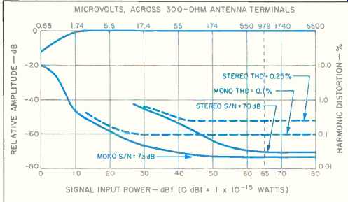
Fig. 1--Mono and stereo FM quieting and distortion characteristics, Model
7 tuner.
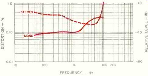
Fig. 2--THD vs. modulating frequency, Model 7.
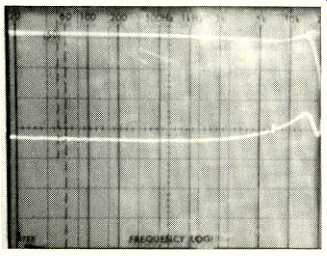
Fig. 3--Frequency response (upper trace) and separation vs. frequency, Model
7.
Figure 3 is a 'scope photo showing frequency response (top trace) and separation for a stereo modulating signal.
The display represents a logarithmic frequency sweep from 20 Hz to 20 kHz. Note the slight rise in response at the high end, just before the steep roll-off above 15 kHz. This sort of curve suggests a slight mismatch or misalignment of the low-pass filters used. In fact, at 15 kHz, response was down a full -5.0 dB, as against-2.0 dB claimed. As for the separation (lower trace), it was consistently good across the entire audio spectrum, though at 1 kHz it failed to reach the 48 dB claimed by Amber, measuring 40 dB instead. Separation at 100 Hz measured 38 dB against 45 dB claimed; at 10 kHz, it measured 28 dB against 40 dB claimed.
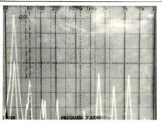
Fig. 4--Crosstalk, subcarrier, and distortion products at output of Model
7's unmodulated channel, with opposite channel modulated 100% by 5-kHz signal.
Sweep is linear, from 0 to 50 kHz.
The Model 7 did not provide what I would consider adequate subcarrier rejection circuitry to get rid of residual 19- and 38-kHz subcarrier products at the tuner output. In Fig. 4, I used a 5-kHz, left-only modulating signal (represented by the tall spike at the left) and then measured the output of the right channel over the frequency range from 0 Hz to 50 kHz. The sweep is linear, 5 kHz per horizontal division. You can see that, in addition to the distortion components at 10 and 15 kHz, there is a fairly large-amplitude spike at 19 kHz and an even taller one at 38 kHz. There are also unwanted components at 33 and 43 kHz (38 kHz plus or minus the 5-kHz modulating frequency). Although none of these are audible (with the possible exception of the 19-kHz component, to those whose hearing range includes that frequency), these spurious components should still be more completely attenuated, since they can lead to IM products that do fall within the audible frequency range.
Output level from the tuner, for 100% modulation by a 1-kHz signal, was 0.75 V. AM suppression measured 55 dB, and capture ratio was 1.5 dB. Alternate-channel selectivity measured 65 dB, a bit better than claimed. Spurious-response and i.f. rejection were both in excess of 100 dB, while image rejection was exactly 70 dB, as claimed. Amber claims only 40 dB for subcarrier product rejection, and that's just about all I measured. AM frequency response is shown in Fig. 5.
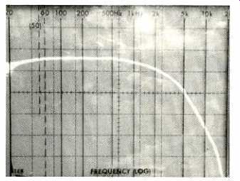
Fig. 5--Frequency response, AM tuner section, Model 7.
Amplifier Circuit Highlights
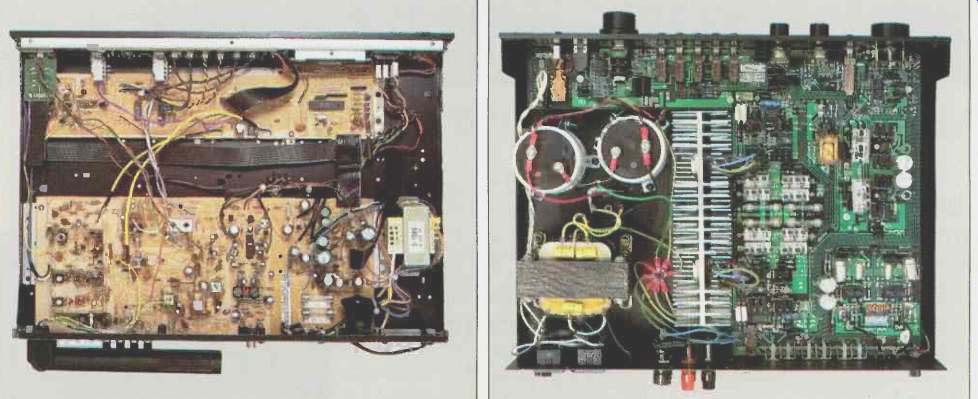
Of the two components that make up this system, the 50b integrated amplifier is by far the more sophisticated in design. Its circuitry begins with a low-pass filter. Voltage amplification is achieved using a complex network based upon National Semiconductor's LM-391N integrated circuit.
(This device consists of a differential input stage with constant current sources, followed by level-shifting Darlington networks and transistor-biasing circuitry.) High-current amplification is provided by four bipolar junction transistors arranged in composite-pair, true complementary, Class-AB configuration. Protection circuitry is not used; rather, the circuit was designed to provide a large safe-operating area. Fuses are incorporated in series with the speaker outputs.
The phono section of the 50b begins with insulated jacks to isolate the very low-level phono signal grounds from all other grounds in the amplifier. Ferrite beads are used on the input lines to suppress any radio-frequency interference. An internal, eight-position DIP switch allows the user to select loading. Phono signal amplification is provided by two gain stages with a passive RIAA equalization network between them. The RIAA network consists of polystyrene and poly propylene capacitors and precision resistors. The entire phono section is d.c.-coupled.
Tone control circuitry used in the 50b employs Baxandall type, active filtering to provide a small, fixed, first-order wave shaping at variable hinging frequencies. The degree of correction (6 dB/octave slope) is kept constant, while the frequency at which boost or cut begins is altered. Treble adjustment begins at 4 kHz or higher, while bass control action begins at 160 Hz or lower. Since these cutoff points are outside the midrange area, accurate midrange reproduction can be maintained while room acoustics or other problems at the frequency extremes are corrected.
Amplifier Measurements
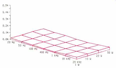
Fig. 6--THD vs. power and frequency, 8-ohm load, Model 50b amplifier.
Considering the care with which this amplifier was de signed, I was surprised to find that the owner's manual did not offer a power-output specification that met FTC format requirements. The Federal Trade Commission requires that all power amplifiers for home use have a uniform statement of rated power output. This statement must include the continuous rated power with both channels driven into a specified resistive-load impedance. It must also specify the range of frequencies over which that power can be achieved at a specified rated harmonic distortion. In their listing of specs for the 50b, Amber tells us only that the amplifier will deliver 50 watts into 8 ohms at 1 kHz. They further state that the rated THD at that 1-kHz test frequency will be 0.006%, and then qualify that statement by saying that the measurement is "A-weighted." Never before have I run into any amp's specification where mid-band distortion measurements are "A-weighted"! Think about this for a moment. If you have a 1-kHz signal, the harmonic-distortion components, if any, will occur at multiples of that frequency (2, 3, 4 kHz, etc.). When an A-weighting network is introduced (the one usually for signal-to-noise measurements), the filter curve of such a network attenuates treble frequencies above around 1 kHz. So, in effect, any harmonic-distortion components produced by the amplifier, using a 1-kHz test signal, will be attenuated by the A-weighting filter, and the result will be a lower overall distortion reading than would otherwise be the case. That kind of spec writing is out of place for an amplifier as intelligently and honestly de signed as this one otherwise is.
I used no such A-weighting network when I measured THD for this amp. Even without it, I measured a distortion level of 0.0065% at 50 watts output per channel, using 8-ohm loads. At the frequency extremes, distortion increased to 0.035% for a 20-kHz signal at 50 watts output, and to 0.017% at 20 Hz. Such low distortion levels are nothing to be ashamed of, and I can't understand why Amber chose to quote power output in the strange manner that they did.
Using 4-ohm loads, the amplifier easily delivered 90 watts per channel, with a THD of only 0.015% to 0.02% at mid-frequencies, 0.3% at 20 Hz, and 0.3% at 20 kHz. Clipping occurred at 56 watts per channel with 8-ohm loads and at roughly 100 watts per channel with 4-ohm loads. The "three-dimensional" curves of Figs. 6 and 7 show how distortion varies with output power and frequency for the 8- and 4-ohm load conditions, respectively.
Dynamic headroom of the 50b amplifier measured 1.2 dB using 8-ohm loads; CCIF IM was a very low 0.0016%. IHF IM was well below the 0.03% lower limit of my measuring equipment. The damping factor, referred to 8-ohm loads, was higher than 125.
Phono input sensitivity was 0.2 mV for 1-watt output, while sensitivity via the high-level inputs measured 20 mV for the same output level. Phono overload occurred with 100 mV of a 1-kHz signal applied to the phono inputs. RIAA equalization on the amplifier I tested was off by a maximum of-1.6 dB at 15 kHz and by +0.9 dB at 50 Hz, rather a lot for an amplifier using such high-quality precision parts in its phono equalization networks. Frequency response via the high level inputs was flat to within ± 1.0 dB from 6 Hz to 30 kHz and to within ±3 dB from 2.5 Hz to 50 kHz.
Signal-to-noise ratio of the phono section was a high 82 dB referred to 1-watt output for 5 mV of input at 1 kHz. For the high-level inputs, S/N was a bit better still, $5 dB. The very moderate action of the bass and treble controls at their maximum cut and boost settings is shown in Fig. 8. With less extreme settings of these controls, even less of the midrange is affected, just as Amber claims.
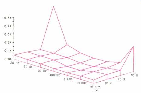
Fig. 7-THD vs. power and frequency, 4-ohm load, Model 50b.
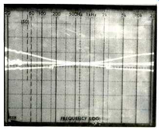
Fig. 8 Bass and treble control range, Model 50b.
Use and Listening Tests
The Model 7's FM sensitivity was excellent, with overall performance adequate if not outstanding. In my location, there was little evidence of interference caused by inadequate selectivity on FM, and I was able to pick up all of the usual signals-about 50 or so-that I expected to intercept.
I should point out, however, that these days there are very few tuners that don't do that well, and some of them are priced a good deal lower than the Model 7.
As for the amplifier, I must confess it sounds a lot better than it measures. In conducting A/B tests between this amplifier and my reference amp in the lab, playing identical copies of several LPs on each, I was able to detect the deviation in RIAA equalization exhibited by the 50b. A slight clockwise rotation of the treble control and a slight counter clockwise rotation of the bass control restored proper tonal balance to these records, but if I didn't have a reference amp to tell me that the sound was slightly off on the 50b, I wouldn't have been able to compensate in this manner.
The medium power rating of this amplifier, combined with the moderate amount of dynamic headroom available, makes it suitable for use with high-dynamic-range program sources (CDs, VHS or Beta Hi-Fi, etc.) only if you are using speakers that boast fairly high efficiencies, or are willing to listen to music at moderate sound-pressure levels.
I think what bothers me most about this combination is its price/performance ratio; nearly $1,100 is a high asking price for a two-piece receiver with the power rating it offers. If price were not a consideration, I would have only high praise for these products, despite the "strange" power-output ratings. But if Amber hopes to compete seriously with off-shore competition, they will have to give us a bit more power for the money-or somewhat lower pricing for the power and performance they now provide.
-Leonard Feldman
[ Orig. publ. in Audio magazine/Aug. 1985]
Also see:
Amber Electronics Series 70 Amplifier (Feb. 1982)
Link | --Armstrong Model 625 Stereo FM Receiver (March 1978)
Audible Illusions Modulus Preamplifier (Nov. 1984)
= = = =