CONTINUED
Discussions of theory are both more easy to understand and more easy to apply, if illustrated by an application associated with something familiar to us. So let's consider the design of inputs and outputs for professional units to be used with 500 ohm line connections.
Professional equipment is designed for line-impedance inter-connections, which means the insertion gain, frequency response, distortion, and dynamic range are all measured and specified when input and output impedances, external to the amplifier or other unit, are each 500 ohms.*
[* Strictly speaking, most professional equipment in the U.S.A. is based on line impedances of 600 ohms, but this does not invalidate the theory presented by the author. -ED. ]
The Problem
This does not say that the internal impedance is also 500 ohms. Quite often it is not. And this fact can lead to wrong operation of combinations of units.
For example, if one unit designed to operate from an external source of 500 ohms, has an internal impedance of 5,000 ohms, and an output to which this input is connected, designed to operate into a 500-ohm load, but having an internal impedance of 50 ohms, we may actually have a 50-ohm source working into a 5,000-ohm load (Fig. 1). This variation from `ideal' can cause a serious invalidation of gain calculations, which may be the least of our worries. What may prove more important is invalidation of specified frequency response and increase in distortion. We'll not go into that further for the moment, but accept it as fact and also note that a desirable remedy would be to make all such units match, in the classical sense.
This means that a 500-ohm input, as well as being intended to operate from a 500-ohm source, will present an input load of 500 ohms. And that a 500-ohm output, as well as being intended to operate into a 500-ohm load, presents a source impedance of 500 ohms at the output.
Before proceeding, let me stress this. Many who went to school and learned the classical matching theory, fondly imagine that connecting a nominal 500 ohms to a nominal 500 ohms automatically achieves this classical concept. It doesn't always, for the reason just stated.
If you don't believe me, please start at the beginning of this article again, and read down to here, before you proceed.
Input Circuit
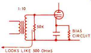
Now for the input end. This is usually the easiest to make right. In amplifiers using tubes, the grid is almost open circuit. An internal load can be achieved, at some loss, by use of resistance that reflects the appropriate value to the external circuit. For example, a 10:1 input step-up may be used, when loading its secondary with 50K will reflect 500 ohms on its primary (Fig. 2) . An actual choice may be to split the loading between primary and secondary.
For example, 1K primary shunt with 100K across the secondary, which would produce an effective parallel value of 500 ohms. This choice would be determined by transformer parameters and response optimization, which we needn't consider further here.
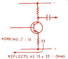
That arrangement doesn't involve feedback. The transistor equivalent does involve a simple concept of feedback, if the input stage operates in the common emitter mode ( Fig. 3) . The base input resistance, with no emitter resistor, is quite low, and non-linear. With an emitter resistor, it is substantially the emitter resistor value, multiplied by the working current gain of the transistor.
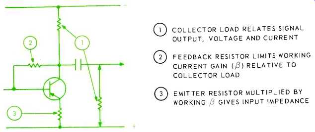
The working current gain is subject to change, with temperature, changing transistors, and so on. So we may use feedback to stabilize this. Obtaining bias for the first stage with a resistor from collector to base provides such gain stabilizing feedback (Fig. 4). In this circuit, the current gain depends on the relationship between the a.c. collector load and the feedback resistor value. Part of the a.c. collector load is the input impedance to the next stage, which will usually be much lower than the collector-circuit impedance of this stage. So the current gain can depend on this base input impedance, which may also be subject to variation and non-linearity.

Fig. 1--Comparison between idealized and working conditions in coupling
between two audio units using nominal 500-ohm line impedance input and output.

Fig. 2-Matching with transformer in old-fashioned tube input circuit.

Fig. 3-How the emitter resistor can provide matched input impedance.

Fig. 4--Showing the effects of principal resistors in an amplifying stage.
COLLECTOR LOAD RELATES SIGNAL OUTPUT, VOLTAGE AND CURRENT OFEEDBACK RESISTOR
LIMITS WORKING CURRENT GAIN ß RELATIVE TO COLLECTOR LOAD OEMITTER RESISTOR
MULTIPLIED BY WORKING ß GIVES INPUT IMPEDANCE
This may be remedied in two ways: either interpose a resistance large enough to swamp such variations, without materially affecting overall gain; or use an emitter resistor in the next stage that stabilizes its input impedance. But that involves other interactions that may reach clear to the output circuit.
Let's put some figures in. Assume we use a transistor with an average current gain (beta) of 100, that may vary between 70 and 140. Assume an appropriate collector resistor is 1K. If we stabilize current gain down to 25, we shall swamp variations due to the transistor. This means the feedback resistor from collector to base should be 24 times the a.c. collector load of this transistor.
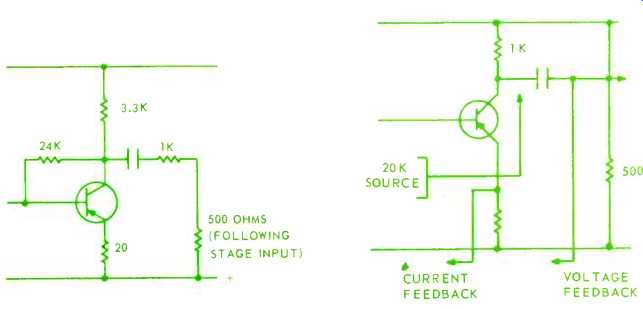
The input impedance of the following stage may be, say 200 to 500 ohms. If we use another 1K as series coupling we shall about halve the current gain passed on to the next stage, but a value this large is needed to swamp input impedance variations. Let's make the collector resistor 3.3K, so most of the current gain is passed to the following stage (Fig. 5). Now the a.c. impedance in the first stage collector is 3.3K in parallel with 1K plus the next-stage input impedance, say 500 ohms, making about 1K for the parallel load value for the first-stage collector. The feedback resistor should be 24 times this, or say 24K. Now we want to make the input impedance 500 ohms. So the emitter resistor should be 1/25th of this, or 20 ohms. This circuit will now provide a nice stable, reasonably linear input impedance of 500 ohms, for classical matching.

Fig. 5--Stabilizing current gain of a transistor stage. Fig.
6--Showing voltage
and current feedback.
Output Circuit
The output isn't so easy to fix. For one thing, to keep distortion low, we need a fairly large amount of feedback, taken from the output to a suitable injection point nearer the input. It shouldn't be injected right at the input, in any part of the stage just discussed, because that would also invalidate the simple achievement we have just discussed. And we've linearized the input stage pretty well by what we have just done.
But we must think of a suitable output stage, with provision for lashings of linearizing feedback. We have a choice: voltage or current feedback, or a combination of both.
Assume that we select an operating condition that gives good linearity as a starting point from which to allow feedback to improve, when loaded by the nominal 500 ohms. Possibly a 1K collector resistor, with the collector resistance (internal to the transistor) of the order of 20K (Fig. 6). With 500 ohms as external load, the parallel impedance from which voltage feedback will be taken is 330 ohms. Say we use 26 dB feedback-a gain-change factor of 20: this will reduce effective output impedance from 330 to 16.5 ohms.
But the actual external output load remains 500 ohms. So the effective internal impedance, with this much voltage feedback, must be just over 17 ohms, to make the parallel combination with 500 come to 16.5 ohms.
Let's try the alternative: current feedback. The logical place to derive this would be off an emitter resistor. Now we must regard the output differently.
Short-circuiting the output removes voltage feedback; but open-circuiting the output does not completely remove the current feedback.
Removing the 500-ohm external load changes the collector load from 330 ohms to 1K. The transistor's internal collector resistance is about 20K, so the current gain would change only in the ratio 20.33:21, a very small percentage. The major effect of removing the 500-ohm external load, with 26 dB of current feedback, would be to multiply output signal voltage by almost exactly 3, while the signal current delivered by the output transistor hardly changes.
With this current feedback, the effective source resistance is still substantially 1K--the output-collector resistor. The effective internal collector resistance may rise 20 times, but the 1K resistor is still there.
To sum up then, 26 dB voltage feedback reduces internal impedance to about 17 ohms, while 26 dB current feedback makes little difference to the internal impedance 'seen' by the external impedance. How can we use 26 dB of feedback to achieve the classical matching value of 500 ohms? The fairly obvious answer is to use voltage feedback to bring the internal impedance down to 500 ohms, and then use current feedback for the rest. How much voltage feedback do we need? The parallel collector load, without feedback, is 1K paralleled with 500 ohms (external assumed). With feedback, it should 'look like' 500 paralleled with 500, or 250 ohms. So the needed gain change, due to voltage feedback, and with the load connected, is 33/25, or 4/3 (about 2.5 dB).
If voltage feedback reduces gain by 3/4, then current feedback needs to take 20 x 3/4=15 reduction. The current feedback AB factor needs to be 14. The total feedback reduction needs to be 20, so the total AB factor should be 19, using the same ‘without feedback' reference signal. As 14 of this is current feedback, this leaves 19-14=5 for the voltage part.
Before going to a practical design, lets check our reasoning by seeing what happens when we change the external load from 500 ohms to either open-circuit or short-circuit.
With nominal load, the total feedback factor is 1+14+5=20. How the feedback changes due to change in load will determine how the drive for the output stage changes.
If we open -circuit the output, the current -feedback AB product remains virtually unchanged at 14, while voltage feedback is multiplied by 3 (because collector load changes from 330 to 1K), from 5 to 15. So the total feedback factor is now 1+14+15=30. Open-circuiting the output will have two effects: the without-feedback gain of the output stage is tripled; while the feedback factor increases from 20 to 30, reducing gain by 2/3. The overall effect is that output voltage doubles, which is what removing a matched load should cause.
Now if we short-circuit the output, the current AB product remains at 14, while the voltage feedback disappears, to make the feedback factor simply 1+14=15.
Thus current gain rises by 20/15, or 4/3. With the 500-ohm load, the load receives 2/3 of the current output, the other receives 35 of the current output, the other 1/3 being spent in the 1K collector resistor. When the output is short-circuited, the short-circuit gets all the current, which is raised by 4/3, or is double that in the 500-ohm load: again the condition of a matched load.
Thus this check supports the theory on which we based out feedback calculations. In the next installment, we'll apply this to completing a workable design.
(adapted from Audio magazine, Apr. 1970)
Also see:
Negative Feedback by Norman H. Crowhurst (May 1970)
More on Negative Feedback (Feb. 1970)
= = = =