by Norman H. Crowhurst
Let's START our feedback circuitry study with a fairly familiar type of tube circuit (Fig. 1-1). Here a signal from the output is fed back to the cathode of an earlier, usually the input, stage.
The feedback seems easy enough to calculate, at first sight, until you start trying to do the actual figuring. First you want to know the forward gain, which you could either calculate or measure.
Now you find that the first stage presents a problem. Do you figure the gain with the cathode resistor bypassed or unbypassed? The first inclination is to say unbypassed, because it actually has no bypass. We've noted that some circuits of this kind use a bypassed cathode resistor as well as an unbypassed one of much lower value for the feedback (Fig. 1-2). Maybe it is done that way to avoid this problem.

Fig. 1-1--A simple type of tube amplifier circuit feedback, to illustrate
a question over which some confusion arises. Do we consider first-stage gain
with or without degeneration due to the cathode resistor?

Fig. 1-2--An input stage used in some designs that avoid the question posed
by Fig. 1-1.
To all intents and purposes, the smaller-value resistor is not big enough to produce appreciable degeneration in the first stage itself, and the bypassed cathode resistor provides bias without degeneration. Thus the calculations are easier or, at least, they bypass the problem.
But avoiding a question doesn't always answer it. Sometimes using a much smaller value resistor to isolate the two effects will not provide a workable answer.
In the simpler circuit (Fig. 1-1), do we figure the gain with the cathode bypassed or unbypassed? Suppose this first stage uses a tube with an amplification factor of 100 (at the chosen operating point) a plate resistance of 80K and a plate load of 100K (d.c.) with 390K in the following stage grid, a.c. coupled to it (Fig. 1-3). This makes the a.c. load for the plate 80K, and the gain, working with the cathode bypassed, would be 50. Now assume the cathode resistor, to give correct bias, needs to be 2.2K. While 50 times the grid-to-cathode signal appears at the plate, 50 x 2.2/80 = 1.375 times grid-to-cathode signal appears cathode-to-ground. Unbypassed, the single-stage AB factor is 1.375, or the (1 + AB) factor is 2.375, which represents a feedback of 7.5 dB. The working gain, unbypassed, will be 50 divided by 2.375, or 21.
Rather than working the gain all through the amplifier, we'll skip that and assume that we find, or design it so that, the feedback signal from the output, as measured across the same cathode resistor of 2.2K, is 9 times the grid-to-cathode input signal. In saying it that way, we are ignoring the feedback due to this stage, as we have just calculated it.
The key question now facing us is, how much feedback will we have? The total AB factor, due to both feedbacks, is 1.375 + 9 =10.375. Knowing this, we can figure the effect of removing the feedback in two ways (Fig. 1-4). If we disconnected the feedback resistor from the cathode (A), the feedback factor operative changes from 11.375 (1 + 10.375) to 2.375, to give a gain change of 11.375 divided by 2.375, or 4.8, which is 13.6 dB.
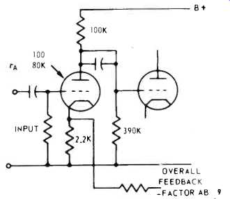
Fig. 1-3--The input stage of Fig. 1-1, with some details put in, for the
sake of calculating an example.
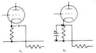
Fig. 1-4--Two ways of "removing" the feedback: (A) by disconnecting
the feedback resistor at the cathode; (B) by bypassing the feedback voltage
at the cathode.
But if we bypass the cathode resistor (2.2K) with a capacitor of large enough value to eliminate all feedback signal, the gain change will be 11.375, or 21.1 dB. So our question is, which is the effective amount of feedback, 13.6 dB or 21.1 dB?
Of course, each of these answers is correct, for the particular way of measuring it: if you open the feedback resistor connection, the gain will go up by 13.6 dB and if you bypass the cathode resistor, the gain will go up by 21.1 dB. But this doesn't answer the question. Suppose the output stage has 4.3 percent distortion at maximum output: how much will this distortion be reduced by the feedback? By a factor of 4.8 or of 11.375? The thing to recognize here is that the input being amplified is the difference between the original (external) input and the feedback signal. The 4.3 per cent distortion of this difference signal (grid-to-cathode of the input stage) will be included only in the AB factor for the overall feedback calculated as 9, yielding a feedback factor, for this purpose, of (1 + AB) =10. So the distortion due to the output stage will be cut from 4.3 per cent to 0.43 per cent. We're making progress.
For distortion reduction, we have 20 dB of feedback, although different ways of measuring the feedback will yield results of 13.6 or 21.1 dB, neither of which is applicable. If you measure the change in distortion, or the change in output impedance due to this feedback, your results will confirm the calculated 20dB feedback factor.
A Tricky Tube Circuit
Before we leave tube circuits to go into transistors, there is another interesting combination feedback problem. It is found in either the unity coupled or the twin-coupled output circuits. We show the unity-coupled version, output stage only, in Fig. 1-5.
In this circuit, the output stage operates each tube as a pentode, using the double-wound primary of the output transformer to provide pentode conditions for each tube. Both primaries have identical turns, in fact, they're usually bifilar wound.
The plates and screens have the same d.c. operating voltage. But the a.c. (signal) voltages, as cathode and screen of each tube swing in the same direction by an equal voltage, are such that the screen-cathode voltage of each tube does not change during the signal cycle. This is pentode operation.
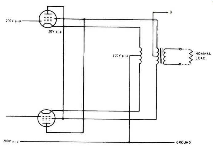
Fig. 1-5--The unity-coupled output circuit that forms the second subject
for investigation in this article. Voltages indicated are developed later
in the text, with the nominal load connected.
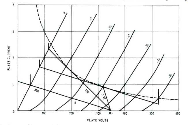
Fig. 1-6--Load lines applied to triode characteristics to illustrate the
problem of obtaining the large swing to drive the output tubes in the unity-coupled
circuit. Three are shown, using 33K and 10K as simple plate resistors (operating
points being indicated by a dot on the line) and a 3K resistor with bootstrap
to make its effective resistance (to a.c.) equivalent to 33K, allowing almost
twice the swing to be obtained.
The plate and cathode-cum-screen of each tube swing in opposing polarity with equal voltages (a.c.). As the grid voltage will be referenced to ground, the cathode-cum-screen half of the total output voltage is feedback to the grid circuit. In referring to half the output voltage, we are taking the tube's viewpoint, not that of the output transformer. As the latter has separate primaries, these may be regarded equally well as series or parallel elements of total output.
Assume that, with normal output load, a grid-to-cathode signal of 20 volts peak produces 200 volts peak each at plate and at cathode/screen. For the output stage, the AB factor is 10, so the feedback factor is 11, reducing output stage distortion, regarded as a push-pull pentode stage, by this factor.
So far, no problem. But now comes the question of providing the drive voltage for the grids, which needs to be 220 volts peak for each output grid. As we shall see, this modifies the figuring we have just done.
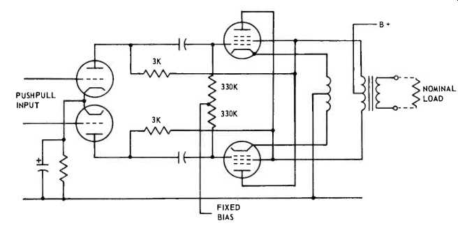
Fig. 1-7--The complete bootstrap circuit that provides the longer load line
of Fig. 1-6 for each tube.
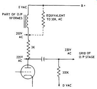
Fig. 1-8--How the bootstrap makes the 3K resistor look like a total of 33K.
Using a pair of ordinary triodes we run into design problems (Fig. 1-6). If we use a plate resistor of high enough value to produce adequate swing, the operating point drops in voltage. If we use a lower value of plate resistor, we lose swing and run into excessive dissipation, in both resistor and tube.
This problem can be neatly overcome by the so-called bootstrap circuit (Fig. 1-7). Here the swing available at the screen of the output stage is used to boost the swing at the plate of the drive stage, using a plate resistor of much lower actual value. The actual resistor of 3K drops only about 30 volts at the plates. The voltage at its "top" end swings 200 volts while the plate swings 220 volts.
From the drive-stage tube's viewpoint, the plate resistor "looks like" 33K (Fig. 1-8). This makes the getting of 220 volts peak to drive the output stage grids a simple matter, and at the same time avoids the need for excessive dissipation. Really, it's positive feedback. But now comes the question: what effect does this positive feedback have on distortion, impedance, and so on? We have already seen that the feedback multiplies the effective plate load for the drive stage by a factor of 11.
Does this mean it also provides further reduction of distortion and output source impedance by the same factor? To answer this, we have to see how the drive swing at the grids of the output stage is affected, relative to the signal input to the drive stage. Assume the drive stage uses triodes with an amplification factor of 20 and a plate resistance of 7.7K. With an effective plate resistor of 33K and following-stage grid resistors of 330K, making an a.c. load for the drive-stage plates of 30K, the stage gain is 20 x 30/7.7 = 16.
But we have no feedback across this stage, unless overall feedback is applied from output to input later, which we haven't considered yet. However, the behavior of this stage can reflect into the output stage source impedance and distortion reduction.
First assume the output stage is somehow driven from a pure voltage source and that the pentode source impedance is 10 times its load impedance. Actually, this value will fluctuate during the signal cycle, but we'll use this as an average.
The combined output impedance, as it would be measured from plate to cathode, is 10/11 of nominal load, when nominal load is connected, without feedback (that is, if the output is rearranged as a regular pentode push-pull, with neither cathodes nor screens swinging).
Now we put in the feedback product of AB = 10, still with nominal load connected. The feedback factor is 11, so the combined impedance is 10/11 divided by 11, or 10/121 of nominal load, measured plate to cathode. Make this a decimal, or 0.0827. Now this includes the nominal load as a parallel element, so the effective source impedance, under this condition is 0.827(1 0.0827) = 0.0904 This represents a damping factor very close to 11.
Now consider how the drive stage affects this. The best way to do this is to ignore output stage nonlinearity and assume that the value of source resistance of 10 times the load impedance is linear. This won't be true, but using is for calculation purposes will enable us to predict smaller changes that don't materially affect linearity.
Still using the 200 + 200 volts peak output, with no load, the grid-to-cathode input to the output stage will only need to be 1/11th of the 20 volts needed when the load is there, or 1.82 volts. Instead of requiring 220 volts peak at the grids, the output stage now needs 201.82 volts peak.
But the factor by which the effective plate resistor of the drive stage is multiplied is changed, from 11 to 121. The effective resistance rises from 33K to 363K. The a.c. load (with the 330K grid resistor coupled in parallel) rises from 30K to 173K. This raises drive stage gain from 16 to 19.1. To give 200 + 200 output with load connected, the drive stage needs a grid input of 220 divided by 16, or 13.75 volts peak. To give 200 + 200 output without the load connected, the drive stage needs 201.82 divided by 19.1, or 10.5 volts peak.
Viewed the other way, if the amplifier is operated below its clipping level (in both conditions) with constant input to the drive-stage grid, the output voltage will rise in the ratio 10.5:13.75 when load is removed. So the effective source resistance is the nominal load multiplied by 3.25/10.5.
(3.25 = 13.75 - 10.5)
So with the bootstrap drive, the source resistance is 0.31 times the nominal load, or the damping factor is 3.2, as compared with the earlier figure, not taking the drive stage into account, of 11.
And what of distortion? This is a difficult question. For one thing there are several sources of distortion now: drive stage as well as output stage, not to mention possible distortion due to the output transformer and the interaction between the output stage and its transformer (causing the cathode and screen not to be perfectly in-phase, for example) .
So we must make some assumptions. Let's assume the output transformer does its job properly and that the drive stage is a perfect amplifier of the characteristic stated earlier (amplification factor 20, plate resistance 7.7K). Effects due to actual drive-stage distortion can then be added afterwards to the consideration of output-stage distortion.
The output-stage nonlinearity will vary the factor by which the drive-stage plate load is multiplied, thus varying gain there. Let's use this fact as a basis for calculating the effects of feedback on distortion. The effect in reducing change of gain will be the same as that reducing distortion.
Assume gain rises by 5 per cent, so the grid-to-cathode input for the output stage needs to drop by 5 per cent.
At the same time, the effective plate resistor for the drive stage rises by 5 per cent and as a result the drive-stage gain rises from 16 to 16.1.
The output stage grid voltage needs to drop from 220 peak to 219 peak. So the drive-stage input would need to change from 13.75 to 13.6 to maintain uniform output. Vice versa, this represents a gain change of 1 per cent, which is what the 5 per cent change is reduced to. So distortion will be reduced by a factor of 5, which is 14 dB. With the bootstrap drive circuit, and assuming the bootstrap circuit is distortion free (which means this must be considered as a separate entity) this unity coupled circuit reduces output stage distortion from, say 4.3 per cent to 0.86 per cent. The reduction anticipated from the discussion of the output stage by itself gave a factor of 11, which would reduce the same distortion to 0.39 per cent.
The positive feedback of the bootstrap circuit doesn't increase the effectiveness of the negative feedback.
Rather it reduces its effectiveness, allowing higher output stage distortion.
Its effect on drive-stage gain is small.
Its major effect is to increase drive stage handling capacity-is something our classic treatment of feedback did not tell us about! It does increase drive stage gain a little, but the handling capacity is its major effect.
And the effect on output impedance is not a reduction by a factor of 11, to yield a damping factor of 11. It yields a damping factor of only 3.2. Of course, these results are subject to modification by further overall feedback.
Next: Transistor Circuits
(adapted from Audio magazine, Feb. 1970)
Also see:
Negative Feedback by Norman H. Crowhurst (Apr. 1970)
= = = =