by H. W. HELLYER
Dust is the great enemy of tape recorder mechanisms. Audio enthusiasts care for their disks as a mother cares for her child. They wrap them in paper sleeves each time they are stored, preen them with dust collectors each time they are played, and meticulously remove all the goo they can find--and some they may only imagine--from the precious stylus point. But too many tape recorder users are content with a perfunctory wipe over the recording and replay head faces when high-frequency losses become too painfully obvious. Tapes may be stored in boxes, but no special care is taken to exclude dust or the creeping effect of humidity, and this is transferred to the head at first play.
Perhaps the reason for this neglect is that spacing-effect losses are not always so obvious to the listener in their early stages as are the pops and crackles evinced by a dirty disk.
Losses of this sort begin at the high frequency end of the sound spectrum, and this is where other system losses have their effect, and where the hearing of the listener first begins to fail.
Dirt on the heads is the primary cause of spacing-effect losses. Loss of tape contact on the pole pieces of a head most seriously affects the response of that head. The effect on a replay head is worse when the wavelengths of the `magnets' on the tape are short, (higher frequencies), partly because such short wavelengths have a weaker external field. Movement away from the pole faces causes dropouts.
Dropouts can be measured pretty accurately. Just lately, a good deal of work has been done into their annoyance value, and for a long time a simple formula has been used, expressing the severity of dropouts, thus:

where S is an arbitrary expression of severity, l= length of impurity, d= depth, h=height, t=width of the track and s= tape speed. From this we can see that dropouts are worse at lower speeds and narrower tracks and depend directly on the volume of the impurity.
Unfortunately, this expression could be challenged by any practicing engineer, because the depth of an impurity has such a drastic effect on recording.
The strength of a magnetic field varies as the square of the distance from the source of the flux. So a soiled head that causes a slight loss during replay will cause a much more severe deterioration in signal level and response when a recording made under these faulty conditions is played back with the same head.
The circumstances for recording are similar insofar as dropouts have the same result-a loss of signal. But while the spacing of the tape from the head, caused by the impurity, will reduce signal strength, so will it also reduce the magnitude of the applied h.f. bias field.
Reduction of bias, among other things, causes a lower signal amplitude to be recorded. So the trouble is cumulative, and the tiny scrap of dirt we have ignored impairs playback of a pre-recorded tape by a factor of X but reduces replay of our new recordings by a factor of X', i.e. the square of the distance times the square of the distance. This is why the complaint is often heard when a tape recorder owner brings his machine to the mechanic: "Playback is O.K. but recordings are weak." What he really means is that he has not noticed the slight degrading of replay and has perhaps indirectly on the volume of the impurity.
Unfortunately, this expression could be challenged by any practicing engineer, because the depth of an impurity has such a drastic effect on recording.
The strength of a magnetic field varies as the square of the distance from the source of the flux. So a soiled head that causes a slight loss during replay will cause a much more severe deterioration in signal level and response when a recording made under these faulty conditions is played back with the same head.
The circumstances for recording are similar insofar as dropouts have the same result-a loss of signal. But while the spacing of the tape from the head, caused by the impurity, will reduce signal strength, so will it also reduce the magnitude of the applied h.f. bias field.
Reduction of bias, among other things, causes a lower signal amplitude to be recorded. So the trouble is cumulative, and the tiny scrap of dirt we have ignored impairs playback of a pre-recorded tape by a factor of X but reduces replay of our new recordings by a factor of X', i.e. the square of the distance times the square of the distance. This is why the complaint is often heard when a tape recorder owner brings his machine to the mechanic: "Playback is O.K. but recordings are weak." What he really means is that he has not noticed the slight degrading of replay and has perhaps unconsciously compensated for it with his controls, but the drop in recording strength is very noticeable.
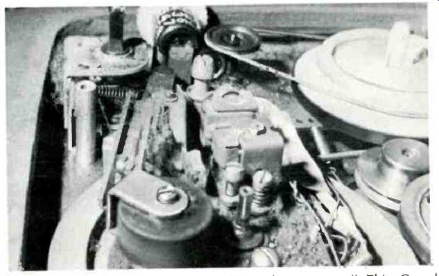
Fig. 1--"Loss of tape contact seriously affects the response." This
Grundig deck collected so much dirt it was a wonder it played at all!
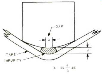
Fig. 2--Spacing loss is 55 dB per wavelength.
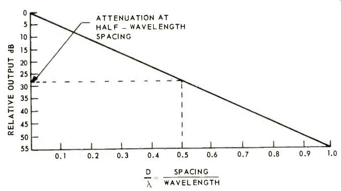
Fig. 3--Showing relationship between attenuation and wavelength.
We can be more precise than this and measure the spacing loss for a given distance (or size of impurity) . Call the attenuation A and the distance of tape from head d, as in Fig. 2, and plot a curve whose vertical axis is the attenuation in decibels and the horizontal axis the spacing in proportion to the tape magnet wavelength, and we get something like Fig. 3. The wavelength depends on tape speed (the higher the tape speed, the longer the wavelength) and the frequency being recorded (the higher the frequency, the shorter the wavelength). Again, we note that the greatest effect is to the higher frequencies, and at the lower speeds.
The tape flux attenuation is given by the formula:

where e is the base of natural logarithms, 2.718, 2.7 pi is 6.28 and X the tape wavelength. So when the spacing equals the tape wavelength d/λ=1 and A=20 log e^2π or 40 Pi log e which is 54.5 dB. So again we can get down to actual figures and say that at 15 kHz, our highest frequency to be recorded, with a tape speed of 3 3/4 in/sec, the wavelength will be 3.75/15,000 or 0.00025 in. So an impurity of only a quarter of a thou' will produce a 54.5-dB attenuation in replay.
That's a voltage ratio of approximately 560:1. The loss after recording does not bear thinking about! The foregoing dip into basic mathematics was quite deliberate. A shock treatment, if you like, to show that head cleanliness can never be taken for granted. A regular and habitual routine of cleaning and degaussing should be part of any tape recordist's schedule.
There are plenty of preparations and cleaning kits available; no need to resort to worn-out toothbrushes and household detergents. The fluids are mild, nontoxic, will not damage plastics, are non-flammable, and should evaporate in reasonable time. Some cleaners carry a small amount of lubricant which is deposited while the carrier is dispelled. In other kits, the cleaner and tape lubricant are separate. One kit, at least, has a pylon arrangement which can be mounted on some decks to provide an extra running surface for the tape, with the lubricant dropped in the pylon to infiltrate the outer felt and provide a slow, regular application to the tape.
When it is necessary to run old tapes through your previous sound channel, this preliminary cleaning can be an invaluable aid.
Other head cleaners may be too mild for cleaning of a heavy oxide deposit from a neglected head assembly. By the look of some tape recorders that arrive in the author's workshop, many owners operate in a coal-hole and have never heard of head cleaning. These have to be tackled with a stiff-bristled nylon brush and denatured alcohol, methylated or surgical spirit. Stubborn deposits are better removed by several ventures than a harder, protracted scrubbing.
When cleaning worn tape heads, always rubs along the line of the tape travel, not up and down. There will have been a tendency for oxide to have collected in any horizontal grooves made by wear, and cleaning this way helps to remove the deposit. Some heads have horizontal slots in the facing, aiding the tape contact by a suction effect. Oxide can build up in these. The nylon brush is the answer, not a poke with a screwdriver blade.
Final cleaning and polishing can be clone with cotton wool on the end of a manicure stick, or, better still, the slightly pliable cotton-wool sticks supplied by cleaning makers.
There are two philosophies about guides. The tape must move in a true horizontal plane, without lateral or vertical wandering, so there must be a degree of back tension. One system requires the trapping of the tape against the head with a fairly tight pressure pad, a roller, or a band. All three types are illustrated in Fig. 3. The alignment is often by a U-shaped piece, perhaps part of the head assembly, or by a closely machined central guide post, keeping the tape in true horizontal traverse.
With this first system, a mu-metal shield on a sprung plate may be used, and this has been utilized as an auxiliary guide in more than one design. Great care has to be taken that this shield slides properly and completely into place and that any felt pad on its inner face is kept soft and free from impurity.
Quite often, this shield is the only guiding the tape gets, apart from vertical machined pins without flanges. It can be demonstrated that a larger-diameter guide is much more efficient as regards tape wear, regularity of control ( freedom from flutter), and lateral guiding effect, yet deck designers continue to fit ridiculously small pins, saving a couple of cents and eschewing the loss in quality.
The second system has critically machined guides whose flanges route the tape precisely across the head gap. Pressure pads, where these are used, only perform the function of keeping the tape in intimate contact with the head facing.
The head shape assumes more importance. Many high-quality decks use no pads, but rely on the wrap of the tape around the head, and the contoured head for which much advantage has been claimed-and challenged-is very much in evidence. One incidental advantage to the maintenance man is that contoured heads are often easier to clean, and keep clean.
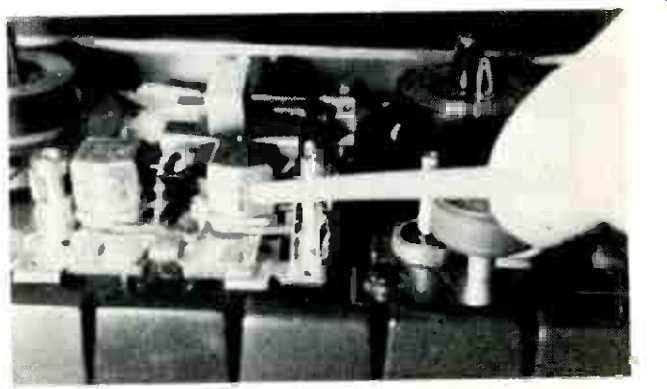
Fig. 4--Sanyo deck with contoured heads.
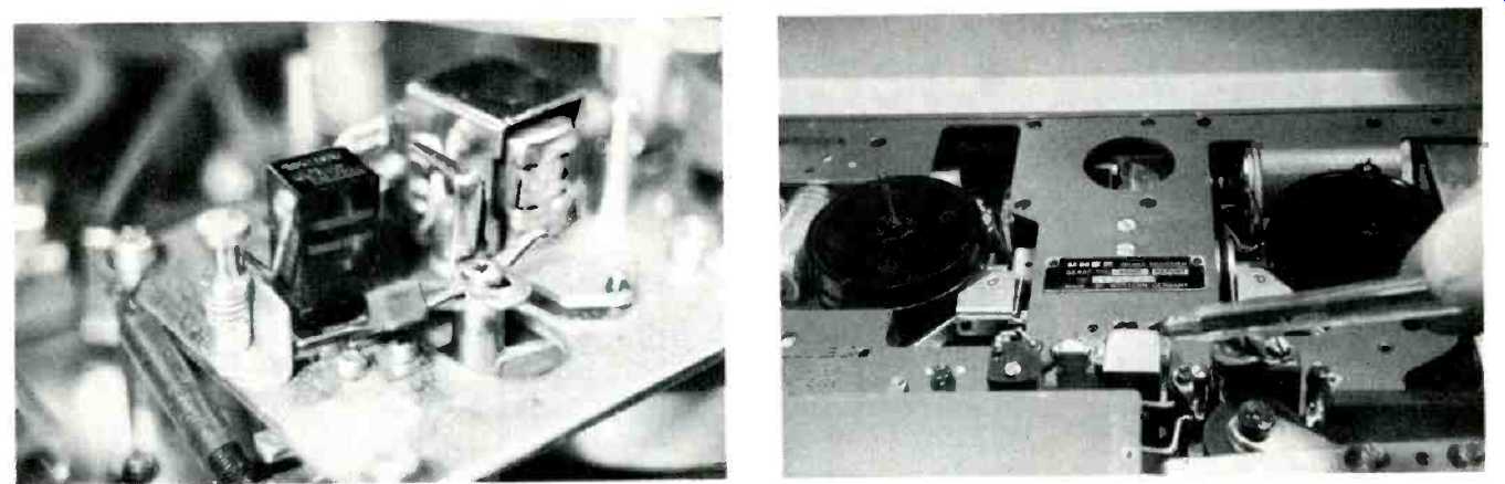
Fig. 5--Sony TC260 showing pressure pad held off by the forked arm from
its contact with the erase head. In this Sony design, the Record/Replay head
relies on the tape wrap for good contact.
Fig. 6--Uher 4000 allows very little access for cleaning and is better served by an impregnated cleaning band.
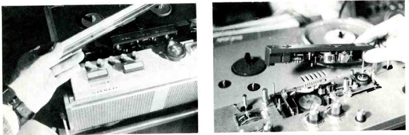
Fig. 7-Accessibility is half the battle! The front trim of this Grundig
deck lifts away completely to allow free access to the heads.
Fig. 8-The Ultimate! In this Uher Varicord design, the complete head assembly can be removed and interchanged for different track formation. Accurate machining of mountings is the secret.
Machined guides present their special problems. Tape width is standardized at 0.246 in. ±0.002 in. Although usually described as ‘quarter-inch' tape, the domestic variety is nothing of the kind.
However, some earlier standards specified 1/4-in. with a tolerance of-6 thou. So some tape is still around with a slightly oversize width, and this can jam in a closely machined guide. Any tape with poor edges, or that has been damaged, should be scrapped. Cut and splice ruthlessly. Tape is not all that expensive: and if there is valued prerecorded material on it, the practice should be to dub it off before the tape falls to bits, using a machine with more-tolerant guide dimensions. Even the less-precise guide formations of medium-class machines, with their ‘play' between tape edge and flange of between 2 and 8 thou. can trap a poor tape; and the build-up of dust and oxide will rapidly diminish the tolerance.
The trouble is that some tolerance is needed, to allow for variations in tape and prevent any tendency to edge curl.
But as the track width of a quarter track tape is only forty thou', any tendency of the tape to wander, aggravated by too generous a tolerance, causes amplitude variations. Tape trapping by narrow-flanged guides or by rough guide barrels will cause flutter during record and play functions and will retard fast winding of many low-torque machines.
This is one of the first areas of investigation when the fault symptoms are that the tape slows near the end of a wound reel.
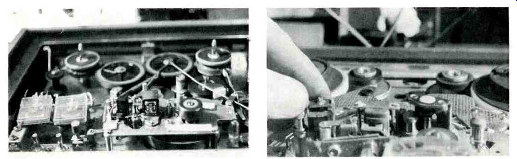
Fig. 9--Showing various adjustable guides on another Sony deck.
Fig. 10--Telefunken deck showing guides before, during and after tape path through channel.
Guides are often adjustable, see Fig. 9. Spring-loaded, with locknut, or simply screwed into the deck, many guides can be set to regulate the datum line for tape travel, and where this is so, setting the guides should be the first job, before any adjustment to the head positioning is made. On a strange deck, always inspect the assembly and look for some fixed datum. It may be the securing of the erase head, a popular method, or the mounting of the plate on which the heads themselves are pivoted: see Fig. 10. Setting the height of the guides according to the maker's instructions is very often an early stage in maintenance and should not be neglected. All the later adjustments that preserve full frequency response, reduce noise, avoid cross tracking, and generally improve recording will depend on this setting.
Occasionally, we run into trouble with tape edges rubbing on spool flanges and the inevitable temptation is to alter the guide position to rectify the error. Before doing this, check the spools themselves and their carriers. The guides seldom go out of adjustment, and if they do, are more likely to exhibit their fault by being loose on their mountings. For adjustment where no information is available, first set the tape run to the fixed datum, then adjust the guides for a level run between spools, noting particularly any tendency of the tape to rub flanges or the top cover of the deck when the spools are turned by hand. After this, set the level of the erase head so that the upper edge of the top track can just be seen above the edge of the tape, stretched tightly against the face of the head. Finally, set the record and replay (or combination) heads so that the upper edge of the tape just cuts the visible upper line of the pole-pieces. In other words, when in doubt, allow the erase head to overlap a little. Signal-strength tests will prove the final setting, and the normal rocking action of azimuth alignment completes the adjustments.
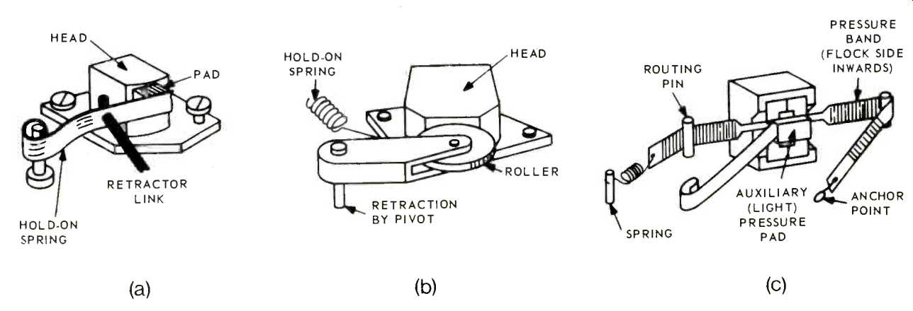
Fig. 11--Three methods of maintaining good contact of tape to head (a) pressure
pad on spring arm, (b) pressure roller, and (c) felted band which a gives
greater degree of wrap.
Plain brass guides, pins, and auto-stop feelers tend to wear badly if dirty tape is used. Quite often, a groove will be made in the rounded surface, and this is a prevalent cause of tape trapping, flutter, and retarded fast winding. View the cleaned surfaces on which the tape bears under a bright light, when these grooves and `flatted' surfaces will be revealed.
Mobile guides such as free rollers, auxiliary brake pins, or tape-end-stop feelers are much in evidence on better class machines. Because they continually present a renewed surface to the tape, they wear less readily, but a tape deck with these devices should be inspected carefully for any tendency to bind. Free running guides should spin freely. Other types, on sprung arms, should swing readily as the tension on the tape is altered.
Watch for compensating springs that have seized, or arms that have bent, throwing the guide axis out of true vertical. Lubricate spindles very lightly, after the usual cleaning. Spring-tension arms have been mentioned in the previous sections on clutches and brakes. From our point of view this month, they can be treated as auxiliary guides and should receive the same careful treatment.
Watch out for the pin or spring guide between the heads, a form of auxiliary adjustment on many models with a sharply sprung pressure-pad plate. This device tends to wear badly when the head-gate assembly becomes cluttered with abrasive dust.
Pressure pads and the plates on which they are mounted have already been mentioned, but the adjustment of these and of the hold-off arms that limit their throw should be rechecked after other adjustments and repairs have been done. Pads must be soft, may need cleaning and perhaps resurfacing by making a small skim with a razor blade. Whatever the action that has been done, it may require a resetting of the inward tension, and this is a final check on the around the head maintenance work channel.
Next: Brakes
(adapted from Audio magazine, Apr. 1970)
Also see:
Tape Transport Maintenance--Part 6--Brakes (Oct. 1970)
Choosing a Tape Recorder (Apr. 1972)
= = = =