
By RONALD WAGNER
[Ronald Wagner is the author of Electrostatic Loudspeaker Design and Construction, published by Tab Books. Since 1968, he has been experimenting with the design of electrostatic speakers.]
Last time, we covered the history and principles of the electrostatic loudspeaker (ESL) and the forces that move its diaphragm. Now it's time to discuss the ways signals are coupled to that diaphragm, its acoustical parameters, and ways to improve ESL performance.
One of the most critical items in an electrostatic speaker is the audio transformer that is connected between the plates and the source of the audio voltage. This device has two interrelated functions. First, it increases the amplifier's output voltage to a value that can produce the required diaphragm movement. Second, it reflects the speaker's capacitance, and its associated impedance, back to the output of the amplifier.
TURNS RATIO
One of the key factors in the performance of a transformer is its turns ratio, which relates the number of turns in one winding to the number of turns in another winding. Although this ratio is not specifically stated in transformer data sheets, it is usually provided in some other form. For an existing transformer, the number can be determined by measuring the voltages on each winding and then computing the ratio between these voltages. That is:
N = V2 / V1 (10)
where N is the turns ratio between the two windings; V2 is the a.c. voltage across one transformer winding, and V1 is the a.c. voltage across another winding.
Besides increasing the secondary voltages, the turns ratio also increases the speaker capacitance that is reflected back to the audio amplifier. As an example, suppose a speaker is to be driven by a 100-watt amplifier. If the amp's full rated power is delivered into a 4-ohm load, then its peak-to-peak output is 56.56 V. When the amp is connected to the 24-inch ESL described last month, this voltage must be increased until the plate-to-plate voltage is 6,250 V. The ratio of these two voltages will establish the trans former turns ratio; in this example, it is 110.5.
Once this value is defined, it can also be used to calculate the speaker's reflected capacitance. Thus:
Cpri= Cspkr x N2 (11)
where Co is the speaker capacitance reflected back to the primary winding of the transformer, and Cspkr is the speaker's plate-to-plate capacitance.
For a plate-to-diaphragm capacitance of 2,074 pF, as discussed last month, Cspkr is 1,037 pF, or 1.037 x 10^-9 farad. Therefore, the reflected capacitance of the indicated loudspeaker is equal to:
Cpri = (1.037 x 10^-9)110.5^2
= 12.7 x 10^-6 farad.
Power amplifiers used for driving loudspeakers are usually designed for load impedances between 4 and 16 ohms. A 12.7-uF capacitor will have an associated impedance, at 100 Hz, of 125 ohms. Because this calculated impedance value is very large, it will affect the speaker's ability to produce the required amount of acoustic power. In addition to this, a capacitor's impedance is not constant. At 10 kHz, for instance, the value will have decreased to 1.25 ohms. Not only can this cause the amplifier to limit its out put power, but the capacitive load can also produce oscillation in the amp.
One way to overcome these difficulties is to use several speakers. If each speaker is operated over a reduced frequency range and connected to the amplifier by a suitable crossover net work, the impedance variation at the amp's output will be less. Another solution is to break a large diaphragm area up into smaller sections. Using this technique, each section is again connected to the amplifier by a crossover network. For higher frequencies, speakers or speaker sections of smaller area are used. More information on this method will be presented in the section on "Segmentation."
TRANSFORMER FREQUENCY RESPONSE
All transformers have frequency response limits. Some, such as power transformers, have very narrow band widths that only occupy a few hundred hertz. Others, used in communication systems, can have a frequency response that spans many megahertz.
A transformer for a single-diaphragm ESL should reach frequency limits of 20 Hz and 20 kHz. For any transformer, the exact location of these limits can be determined by dividing its frequency response into three regions.
Each region is then analyzed by using an equivalent model that predicts how the transformer and its associated load will perform.
The best place to start analyzing a transformer's response is in its mid-frequency range. Within this region, the transformer is considered ideal, and its performance is determined by its turns ratio. To create an equivalent model, the output winding resistance, as well as the load, must be reflected back to the input terminals.
Consider, for example, the transformer circuit shown in Fig. 8A. The resistance (rg) is the internal resistance of the voltage source (es). The resistance of the input or primary winding is shown as re. On the speaker, output, or secondary side of the transformer, the winding resistance is designated as rs. The speaker capacitance is shown as Cspkr.
An equivalent model is shown in Fig. 8B. In this diagram, the two resistances (rg and rp) are unchanged. As indicated, the secondary resistance (rs) is referred to the input or primary winding by dividing its value by the square of the turns ratio (N). The speaker capacitance is also reflected to the input, but its value is multiplied by the square of the turns ratio, as shown in equation 11 above.
Although this circuit does not look very complicated, it can be simplified still further. For instance, most solid state amplifiers have an rg of less than 1 ohm. The primary winding resistance is about the same value, and the two resistances can be combined. The out put or secondary winding resistance is dependent on the wire size and the number of turns. For a transformer used in an electrostatic speaker, this value can vary from 50 to 100 ohms.
When it is referred to the input, it be comes so small that it can be dropped from the circuit, yielding the new circuit shown in Fig. 8C.
Electrically, this circuit is called a low-pass filter. The output voltage across the speaker's capacitance will decrease by 3 dB when the reflected impedance of the capacitance is equal to the combined values of rg and rp. If, for instance, the winding resistance (rp) plus the source resistance (rs) is equal to 1 ohm, then the speaker's upper frequency response would be limited to 12.5 kHz. On the other hand, if this resistance were only 0.5 ohm, the up per limit would be extended to 25 kHz.
Unfortunately, transformers are not ideal, and their high-end response will be determined by a number of other factors. One of these factors, inductance, affects low-frequency performance, too.
A transformer's low-frequency response is determined by the inductance (Lpri) of the primary winding. When the impedance of this winding is equal to rg plus rp, the voltage across the speaker will decrease by 3 dB. Although Cspkr is in parallel with Lpri its impedance is much greater and does not become a factor in the low-frequency limit. The low-frequency transformer model is shown in Fig. 8D, and the location of the -3 dB point can be calculated by:
F= XL / 2 pi (Lpri) (12)
where f is the -3 dB frequency in Hz; XL is the impedance value, in ohms, that is equal to the sum of rp and rg, and Lpri is the inductance of the primary winding, in henries.
As an example, suppose a transformer has a primary inductance of 1.5 mH (0.0015 H). If the total resistance of rg plus rp in the circuit of Fig. 8D is equal to 1 ohm, the transformer's low-frequency limit would be:
f=1/6.28(1.5 x 10^-3)
= 106 Hz.
As already stated, a number of factors must be considered in establishing the transformer's upper frequency limit. The circuit in Fig. 8E shows the majority of these elements. In this type of circuit, the unknown components are the leakage inductance, the interwinding capacitance (Ciw), the secondary-winding capacitance (Cs), and the primary-winding capacitance (Cp).
The model shown in Fig. 8F is an equivalent circuit, with all of the secondary elements reflected to the primary winding. This circuit can also be reduced in complexity. For instance, the secondary-winding capacitance (Cs) is very small when compared to the speaker's capacitance, and it can be removed from the circuit. The value of the interwinding capacitance (Ciw), the capacitance between the two windings, is not multiplied by the turns ratio. However, it can be moved to the input side of the transformer and added to Cp; the combination is shown as C1. As long as the source and the primary-winding resistance are very low, C1 will not seriously affect the transformer's upper frequency limit, and it can be removed from the circuit.
In the transformer's mid-frequency range, the analysis assumes that all of the magnetic lines from the primary winding are linked to the secondary. In actual practice, this is not always true.
The difference between the number of magnetic lines produced in the primary and the number coupled to the secondary yields an additional parameter called the leakage inductance. This inductance can be calculated by:
Li = 2(1- k)Lpri (13)
where Li is the leakage inductance, referred to the primary winding; k is the coefficient of coupling between the two windings, and Lpri is the inductance of the primary winding.
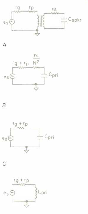
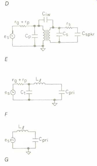
Fig. 8--Transformer circuits and equivalent electric circuits.
In the mid-frequency range, the value of the coupling coefficient (k) is equal to unity, which makes Li equal to zero. As the frequency is increased, the value of k decreases. If k is reduced to 95%, the leakage inductance is equal to:
= 2(1- 0.95) (1.5 x 10^-3)
= 2(0.05) (1.5 x 10^-3)
= 1.5 x 10^-4 H.
As shown in Fig. 8F, this leakage inductance is in series with the reflected load impedance. The voltage across the speaker will be down 3 dB when the impedance of Cpri is equal to the impedance of the leakage inductance. The modified circuit, shown in Fig. 8G, is also a low-pass filter. Its -3 dB point can be calculated by:
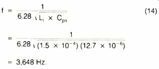
Because the previous calculations have indicated that this transformer has a very poor bandwidth for high fidelity reproduction, it can only be used for midrange speakers. To repro duce the bass and high-frequency portions would require substituting a different transformer. If the full audio spectrum is to be reproduced by a single transformer, that transformer's primary inductance must be greater than the previous value.
Similarly, high-frequency response can be extended by selecting a transformer with a lower leakage inductance. In some instances, this can be achieved by careful transformer de sign. However, this may be very difficult if the transformer has a high step up ratio. One alternative is to use a separate transformer with a lower turns ratio to cover the high-frequency range. Although there are a number of other interrelated factors, this would decrease the leakage inductance and extend the high-frequency limit.
ACOUSTIC PERFORMANCE
The major acoustical parameters of a loudspeaker are its volume velocity, radiation resistance, power output, frequency response, directivity, and distortion. This last parameter is not usually a significant factor in ESL performance.
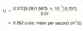
Volume velocity is a measure of how much air the speaker is moving. This is calculated by multiplying the diaphragm area by the rms value of the diaphragm movement, and dividing the result by the required time per cycle. That is:

where U is the volume velocity, A is the diaphragm area, drms is the rms value of the diaphragm movement, and t is time. Using the same diaphragm area and plate-to-diaphragm distance as in Part I of this article, and a frequency of 100 Hz, we get:
RADIATION RESISTANCE
The acoustic power from a speaker is dissipated in the radiation resistance of the air load. Beranek's Acoustics (Table 5.3, page 126) defines the radiation resistance (on both sides of a diaphragm, without a baffle) as being equal to:

where Ra is the radiation resistance, in acoustic ohms; a is the diaphragm radius, in meters; po is the density of air (1.19 kg/m^3); w is 2 π f, and c is the velocity of sound, in meters.
As the radius (a) indicates, Beranek's equation is for conventional, round speakers. To use this equation for our 24-inch square (0.372 m^2) speaker, we must first calculate the radius of a circle of equivalent area, which is 0.344m. Therefore, the value of Ra for this speaker, at 100 Hz, is:

ACOUSTIC POWER
The acoustic power (Pa) produced by the speaker is equal to the radiation resistance multiplied by the square of the volume velocity. That is:
Pa = Ra x U^2 (17)
= 10.13 x 0.263^2
= 0.700 watt.
If this number seems high, it is. The previous calculation for the volume velocity assumed that the entire diaphragm moved the total distance which separated the two plates. Due to the mounting system, this is far from true. As an estimate, the average displacement is about 5% to 10% of this distance. To keep things simple, let's assume an rms value of 0.0125 inch, or 317.5 x 10^-6 m. The corresponding volume velocity will be:
U = 74.2 x 10⁻³ m^3/S, and Pa = 55.8 x 10^-3 watt.
The total power that must be sup plied by the source is equal to the power dissipated in the radiation resistance and the power needed to move the diaphragm. That is:
Pin = Pm ± Pa (18)
where Pin is the input power to the speaker; Pm is the power required to move the diaphragm (which we calculated in Part I as 0.468 watt), and Pa is the power expended in the acoustic resistance. Thus:
Pin = 0.468 + (55.8 x 10^-3)
= 523.8 x 10^-3 watt.
EFFICIENCY
When the input and output power are known, they can be used to deter mine the speaker's efficiency. The ratio of these two values indicates that our 24-inch square speaker has an efficiency, at 100 Hz, that is equal to:
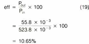
...where eff is percentage of efficiency.
At first, this number may also seem high. It has been stated that the efficiency of a conventional dynamic speaker is often less than 10%. Some articles on ESLs have also indicated that an electrostatic speaker's efficiency is about the same as a dynamic speaker's. The apparent discrepancy between this and our figure of 10.65% is a matter of definition.
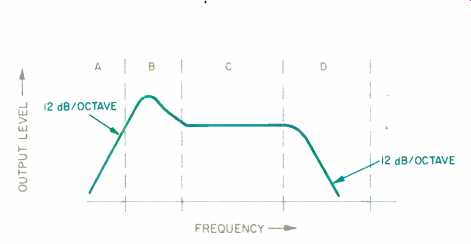
Fig. 9 -- Speaker output vs. frequency; see text.
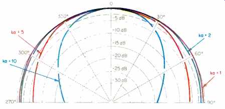
Fig. 10 -- Speaker directivity vs. wavelength for four values of ka.
In his 1955 Wireless World article, "A Wide Range Electrostatic Loudspeaker," P. J. Walker stated that "The true efficiency of an electrostatic speaker is very high indeed, but it is difficult to realize because of the large wattless current which has to be provided due to the electrical capacity of the loud speaker."
To illustrate this point, let us calculate the a.c. current flowing through an ESL's capacitance:
I-V X Cpri t (20)
where I is the peak a.c. current flowing through the speaker's plate-to-plate capacitance; v is the peak a.c. voltage across the two plates; Cpri is the speaker's capacitance as reflected back to the transformer primary, and t is the time required for the voltage to reach its peak value. For our 24-Inch square speaker, with its reflected capacitance of 12.7 uF, and an amplifier with a peak-to-peak output voltage of 56.56 V, the peak current flow is:
28.3(1.27 x 10⁻⁵) 2.5 x 10^-3
= 144 x 10^-3 ampere.
If the rms value of the input voltage is multiplied by a similar value for the current, the result is the apparent power being supplied by the source (Papp):

.
When this value is used to calculate the speaker's efficiency, the result is closer to a conventional speaker's:
eff=55.8 X 10^-3 / 2.04 x 100
= 2.74%.
This calculation reinforces P. J. Walker's statement about the loudspeaker's efficiency.
Note that this efficiency figure is frequency dependent, as the current value used in equation 21 was derived from equation 20, whose time factor is a function of the signal frequency.
SPEAKER FREQUENCY RESPONSE
The frequency spectrum that a loud speaker must cover can be divided into four areas. The cone or diaphragm movement is controlled, in each of these areas, by one or more speaker parameters. In Fig. 9, the peak in region B is the speaker's resonant frequency. This point is a function of the diaphragm's mass and the compliance of the mounting system. The height of the peak is controlled by both the electrical resistance (such as rg, rp, and rs) and the opposition produced by the diaphragm's air load (Ra).
Below the resonant frequency, in region A, the diaphragm motion is con trolled by the compliance of the mounting system. In this region, the acoustic output falls at a rate of 12 dB/octave, and the speaker's output is generally not usable.
to the C region, the output is deter mined by the mass of the air load. Most textbooks indicate that the speaker's performance is related to a factor called ka. The "k" value is frequency dependent and is equal to (1.83 x 10^-2)f. The "a" is the speaker's radius, in meters. For our square speaker, using one-half the width provides a reasonable approximation (304.8 mm), which will be used in some of the calculations to follow.
Over most of the C region, the reactance of the air mass (Xm) rises in direct proportion to the increasing frequency, reaching a maximum value when ka is between 1 and 2. Because of this reactance rise, the diaphragm's movement will decrease and the speaker's output will remain constant.
When the frequency exceeds the point where ka equals 2, the reactance of the air mass decreases and the speaker's performance enters region D.
The radiation resistance (Ra) is also increasing in region C, but its value goes up by the square of the increasing frequency. Except for the region where ka is between 1 and 2, the radiation resistance is always less than the reactance. It is the radiation resistance that determines the radiated acoustic power.
In the last region, D, above the point where ka equals 2, the amplitude falls because the response is controlled by the radiation resistance. In this region, the reactance of the air mass is considerably less than the value of the radiation resistance.
As indicated, diaphragm resonance determines the lower limit of the C region. For our 24-inch square speaker, this is approximately 30 Hz. The boundary between regions C and D can be determined by calculating the frequency that will produce a ka factor equal to 1:
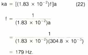
This frequency is a long way from the upper limits of the audio spectrum, and some method must be found to extend its value.
In a conventional speaker system, the solution is to use several drivers of different sizes to cover the entire audio range. While this same technique has been used in some ESLs, there is an alternative method.
Instead of using separate drivers, the plate or diaphragm area can be divided into a number of smaller sections. Because the speaker's width determines where ka equals 1, only this factor needs to be made smaller. In equation 17, it was stated that the speaker's power output is a function of its volume velocity and its radiation resistance. If its width is made smaller, its length should be increased so that the area remains about the same.
SEGMENTATION
Segmentation is the division of the plate or diaphragm area into smaller sections. As an example of this technique, suppose the speaker's 24-inch width is divided into six sections, so that the widest part is 12 inches, and the rest of the speaker is divided into sections of 4, 2, 1, 0.5, and 0.25 inch es. (The total will not equal 24 inches.
Some space is used to separate each of the sections, and the remainder is needed for the diaphragm-to-plate spacers.) For the above sizes, the corresponding upper frequency limits are 360, 1075, 2150, 4300, 8600, and 17,200 Hz.
If these sections are combined through a suitable crossover network, then the entire diaphragm will radiate as one piece below 360 Hz. Above this frequency, the output from the 12-inch section will decrease, and the remaining part of the diaphragm will continue to provide the speaker's acoustic output.
When the frequency exceeds 1,075 Hz, the speaker's effective size will again decrease, and the four remaining sections will continue to supply the acoustic output. As the frequency continues to rise, the output from each of these sections will decrease, and at 17.2 kHz, only the 0.25-inch section will be acting as a speaker. This segmentation is very useful in maintaining the system's frequency response.
A speaker driver's dimensions affect not only its high-frequency cutoff but also its directivity at higher frequencies. As the frequency increases and the reproduced wavelength begins to approach the diaphragm's diameter, the speaker's radiation angle narrows.
Some electrostatic speakers use curved diaphragms to increase their radiation angle, but flat or planar speakers must change their effective width with frequency (such as by segmentation) to eliminate the beaming effect. The polar plot of Fig. 10 indicates a speaker's radiation pattern as a function of ka. Because a hemispherical pattern only occurs when ka is less than 1, the diameter of a speaker must be reduced as the frequency is increased.
For instance, suppose it is desired to radiate a 20-kHz signal over an angle of ± 90°. The wavelength is equal to:
wavelength =speed of sound / frequency
13,440 inches / 20,000
= 0.672 inch. (eqn. 23)
To obtain the required radiation angle, the speaker's radius must not exceed one-third of the wavelength. Al- though this would make the speaker's diameter equal to 0.224 inch, the 0.250-inch segment of our ESL causes only a slight modification of the desired frequency response and directivity pattern.
IMPROVING ESL PERFORMANCE
Some audiophiles feel that an ESL does not produce enough bass, and they have tried to modify the low end by adding a conventional cone woofer.
This type of modification can produce a number of undesirable effects. First, the bass can easily be overemphasized, destroying the sonic balance that is inherent in the design of a wide-range electrostatic speaker.
Another problem with adding a conventional speaker is increased distortion. Most ESLs have a distortion value that is less than 0.1%; a conventional speaker's distortion is 10 to 100 times greater.
INCREASING ACOUSTIC OUTPUT
From a manufacturing standpoint, the acoustic output of a speaker can be increased by altering its diameter, its cone or diaphragm displacement, the number of drivers, or all three.
In an ESL system, some of these factors are difficult to change. For in stance, when the plates are moved farther apart to obtain greater diaphragm movement, the reflected capacitance will decrease and the speaker's impedance will rise. To compensate, the transformer's turns ratio must also be increased. Although this will restore both the impedance and the a.c. field strength, it will also increase the trans former's leakage inductance. In addition, the charging voltage for the diaphragm must then be increased in order to maintain the same field strength.
If the diameter is made larger, some other design changes must be made.
One critical factor is to keep the diaphragm uniformly suspended between the plates. The increased size will also require additional segmentation.
MULTIPLE DIAPHRAGMS
The simplest way to produce more output is to add additional panels.
When two or more panels, radiating the same frequency, are placed next to each other, the amount of air being moved increases.
Volume velocity, which is the mea sure of this air movement, is similar to the current in an electrical circuit. If the current is doubled by connecting two current generators in parallel, then the resulting voltage across the load will also double.
Placing two or more speakers next to each other creates, in effect, a parallel configuration. The volume velocity will increase, and this will develop a greater acoustic pressure across the radiation resistance. The result will be an increase in acoustic power.
The biggest problem with increasing output by paralleling additional diaphragms is the effect on the speaker's size. It might at first seem reasonable to parallel two of the speakers shown last month in Fig. 3. This system uses two 24-inch square diaphragms, one above the other. However, paralleling would make the speaker 4 feet wide, in which case a stereo pair would occupy a space of 8 feet. Proper placement could then be obtained only in a very large listening area.
In addition to the side-by-side parallel configuration just described, it is also possible to increase a speaker's output by creating a serial configuration, with one speaker placed behind the other. This increases the speaker's bass response but does not change its width.
In this configuration, the pressure produced by the front diaphragm is increased by the pressure from the rear diaphragm. The electrical equivalent of this would be connecting two voltage generators in series, which would increase the output voltage and produce a corresponding increase in current. Acoustically, the increased pressure from the serial diaphragm arrangement will also increase the volume velocity. The radiated power for either the parallel or serial configuration will go up by a factor of 4.
It may seem relatively easy to add an entire second panel or speaker behind the first, but commercial implementations actually use two diaphragms sharing one common plate (Fig. 11). If the two diaphragms are very close--less than 0.1 inch--then the speaker will work as indicated.
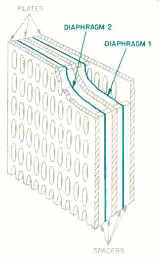
Fig. 11--An electrostatic speaker using dual diaphragms in a serial configuration.
Should the design prevent such close spacing, then the rear diaphragm must operate over a reduced frequency range. The reason for this is sound cancellation. When the two diaphragms are in series, their outputs will add, as long as they are in phase.
When the frequency rises to the point where its half wavelength is equal to the distance separating the diaphragms, the sound from the second diaphragm will arrive at the first diaphragm in opposite phase. When this happens, the two waves cancel and the speaker produces no output. But even at lower frequencies, whose half wavelengths only approach the inter-diaphragm distance, partial cancellations occur and cause a roll-off.
The Harold Beveridge patent mentioned in Part I describes a speaker that uses this minimum-separation serial construction, although I have been unable to find out if any speakers were ever produced under this patent. The Sound-Lab Co., of Park City, Utah does produce a serial-diaphragm speaker (Fig. 1 in Part I). Its frequency response is limited to the range below 350 Hz, but the company does not say if this is a minimum-separation design.
The use of multiple diaphragms in an electrostatic speaker should overcome any listener's objection to the speaker's lack of bass, without altering the ESL's advantages of correct tonal balance and extremely low distortion. The result is a loudspeaker whose sound quality can only be duplicated by a live source.
SUGGESTED READING
Beranek, L. L., Acoustics, McGraw Hill, 1954.
Walker, P. J., "A WideRange Electrostatic Loudspeaker," Wireless World, May, June, and August 1955.
(adapted from Audio magazine, Apr. 1989)
Also see:
Electrostatic Speakers: Theory and Practice -- Part 1 (Mar. 1989)
= = = =