Ralph E. Gonzalez
[Dr. Ralph E. Gonzalez is an Assistant Professor of Computer Science at the Camden, N.J. campus of Rutgers University. He also designs and manufactures Delaware Acoustics loudspeakers.]
Unless you own a good sub woofer, chances are your system does not reproduce much of the lower bass range-those frequencies below about 50 Hz. In addition, many otherwise outstanding speakers exhibit a peak or a prematurely falling response near the bass cutoff frequency. The electronic circuit described in this article can be applied to nearly any acoustic-suspension loudspeaker to smooth the bass response and produce a range of possible bass extensions. In effect, it allows your speaker to function like a speaker with a much deeper, well-controlled bass response.
Acoustic-suspension speakers have a corner frequency (fs) below which heir output drops by approximately 12 dB for every octave. Figure 1 shows bass response curves for typical acoustic-suspension speakers, for various values of Qs. This parameter, which is related to a speaker's damping, indicates the output level of the speaker at its corner frequency in relation to its output at higher frequencies.
For example, for Qs equals 0.7, response is down by 3 dB (-3 dB equals 20 times the logarithm of 0.7) at s. For Qs greater than 0.7, a bass peak begins to appear slightly above fs. (The frequency of this peak is the resonant frequency, a term often somewhat incorrectly applied to fs.) In speakers whose Qs is less than 0.7, a prematurely falling response is seen. The former case corresponds to some of the bass heavy speakers on the market, while lightweight-sounding speakers would tend to have low values of Qs.
Interestingly, while a Qs of 0.7 gives the "maximally flat" (or Butterworth) response, a Qs of 0.5 gives the "critically damped" response. Figure 2 shows the transient response of various hypothetical acoustic-suspension woofers when fed a "step" input, an electrical test signal consisting of a sudden increase in voltage. (The horizontal axis in Fig. 2 represents time, so that you see the output of the speaker for the fraction of a second following the step input.) A speaker would require a flat response down to 0 Hz to accurately reproduce the step; the response of a typical speaker will instead drop back to zero soon after the step is applied. If the speaker's Q. is greater than 0.5, it is underdamped and begins to show ringing before returning to zero. The frequency of this ringing is close to the corner frequency. Depending on its severity, ringing can cause a subjective impression of muddiness or boominess in the bass region. Although comparatively few speakers have Qs less than 0.5 (overdamped), those with Qs between 0.5 and 0.7 are usually considered well damped and tend to sound tight and fast in the bass.
By comparing Figs. 1 and 2, you can see that tight bass is often prematurely falling or lightweight-sounding. The only way to simultaneously obtain good bass transient response and good bass frequency response is to ensure that your speakers' corner frequency is below the frequency range of your music.
===========
BASSIS SPECS.
Frequency Response: 5 Hz to 100 kHz, +0,-0.5 dB, with "Boost" at zero and Qs equal to Qb.
Harmonic Distortion: Less than 0.01%.
S/N Ratio: Greater than 110 dB, re: 10 V.
Bass Boost Range: 0 to 24 dB (zero to two octaves).
Net Q Range: 0.25 to 1.0.
Input Impedance: 80 kilohms.
Output Impedance: 10 ohms.
Dimensions: 17 in. W x 2 3/4 in. H x 8 1/2 in. D (43.2 cm x 7.1 cm x 21.6 cm).
============
Here is where speaker designers get headaches, since there is a binding relationship between a given woofer's fs, Qs, and enclosure volume. The average bookshelf speaker winds up with a corner frequency around 60 or 70 Hz and a Qs in the range between 0.5 and 1.4. The bass below 50 Hz is usually lacking, but equally important, the frequencies above 50 Hz may be depressed or may be elevated and peaky, depending on whether the designer feels that tight bass is all-important or that a boomy bass will give the subjective impression of lower bass extension.
It is possible, however, to electronically correct a speaker's response to give it the equivalent of a much lower, well-damped corner frequency. This method will not give you the kind of boost you get by turning up the bass control or pushing the loudness button on your preamp or receiver. Instead, if your speakers are somewhat under damped, you will hear an improved neutrality and openness in the mid bass. If your speakers are well damped or overdamped, you will hear an added weight to the music. With either type of speaker, and with recordings containing significant low bass information, you'll experience a "you are there" sense of impact.
Of course, many recordings have little musical energy below 40 Hz, and FM radio and cassette reproduction often reduces this even further. If your speakers have reasonably deep, tight bass to start with, you may have little need for electronic bass equalization.
On the other hand, CD is putting a greater focus on the reproduction of low bass frequencies than ever before.
ENTER THE BASSIS
Correcting a speaker's bass response electronically requires a specialized parametric equalizer which can be adjusted to specific speakers' requirements. This led me to conceive the idea for such an equalizer, the Bas sis, which is designed to exactly compensate for an acoustic-suspension speaker's bass roll-off, yielding the same net response as a speaker with a deeper, well-damped corner frequency. (I'll show later how it may be applied to vented speakers as well.) Its effect is most dramatic with smaller speakers, but even some subwoofers can benefit from its use, There are, obviously, practical limits to the bass extension that electronics can provide. Boosting low-frequency signals calls for more power from the amplifiers and greater excursion from the woofer cones. Too much boost will cause audible distortion from the amplifiers, the speakers, or both. If this distortion is ignored, and enough amplifier power is available, speakers can be permanently damaged. This is especially true of smaller speakers.
The device, which may be inserted in a tape loop or between preamp and power amps, is available fully assembled or in kit form from Marchand Electronics, who engineered the actual circuit. A version with balanced inputs and outputs is under consideration, should there be enough demand.
Figure 3 shows a theoretical example of the circuit's effect. As you can see from its unequalized response, the speaker shown here is underdamped (with a Qs of 1.4) and has a roll-off at an fs of 60 Hz. Through proper adjustment, the Bassis can provide a boost (dashed curve) that is the inverse of the speaker's curve, down to about 15 Hz. The equalized response to signals passing through the combination of equalizer and speaker then becomes identical in both frequency and transient response to that of an unequalized speaker whose-3 dB point is 15 Hz. Note that it is generally not possible to perform this sort of equalization with a conventional graphic equalizer, since the frequency bands affected by each slider are too wide and are often centered at the wrong frequencies for a given woofer.
As seen in Fig. 3, one of the effects of the Bassis is a boost in the level of low-frequency signals, adjustable up to 24 dB. Every octave of bass extension requires 12 dB of boost. Fortunately, the amount of very low frequency energy in recordings and even live music is usually relatively low, with the exception of signals sometimes generated by record warps. (An infrasonic or "subsonic" filter helps eliminate that potential problem.) For this reason, many designers, notably Laurie Finch am of KEF, consider a moderate boost (up to about 12 dB) of the frequencies below about 50 Hz to have a relatively minor effect on amplifier and speaker power handling. Interestingly, it has been demonstrated that equalizing a woofer in a small enclosure to yield the bass it would have in a larger enclosure often results in lower bass distortion than could be obtained with the larger enclosure. This is because the suspension effect produced by the air trapped inside a small enclosure is usually more linear than the woofer's mechanical suspension. Naturally, it may be wise to reduce the amount of boost when listening to small woofers at high volume levels, particularly with a bass-heavy recording.
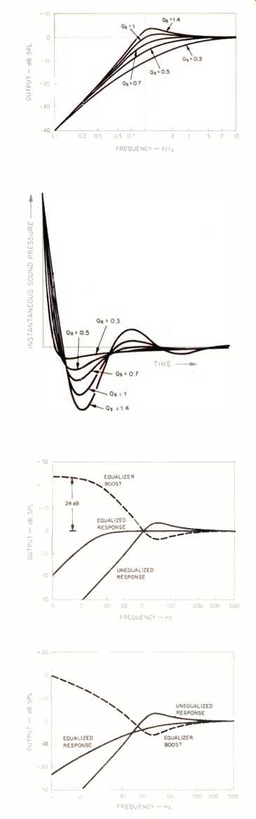
Fig. 1--How bass response of acoustic-suspension speakers varies with Q.
Fig. 2--Step response of acoustic-suspension speakers for various values of Q.
Fig. 3--Effect of a 24-dB bass boost with corner frequency of 15 Hz and a Qb of 0.7 on a speaker with a 50-Hz corner frequency and a Qs of 1.4.
Fig. 4--Effect of overdamped boost ( Ob equal to 0.25) on the speaker of Fig. 3.
The Bassis also provides adjustable damping (Qb) for the new bass roll-off.
Figure 3 shows the net response with a at) of 0.7, but lower (better damped) values of Qb are also possible. For example, Fig. 4 shows the response of the same speaker after being equalized with a Qb of 0.25 and with the same 15-Hz setting for the new corner frequency (fb). Now there is significantly less bass boost in the audio range, and the net response is gently falling.
In effect, the roll-off of 12 dB per octave at 60 Hz is replaced by a roll-off of 6 dB per octave at the same frequency. Such a bass response has several advantages. First, bass is extended without introducing a drastic boost at low frequencies. Second, this extremely overdamped roll-off has no ringing and resembles the response of the highly regarded transmission-line form of bass loading, without its relatively large associated enclosure size.
If additional bass extension is not desired, the Bassis can be used with a zero-boost setting to effectively vary the woofer's damping while retaining the original corner frequency. This setting is useful for vented enclosures as well, to reduce the boominess of improper tuning. (It is generally unwise to apply a boost below the corner frequency of a vented speaker.) Of course, you can plug the vent of a bass-reflex speaker and use the full range of equalization options. By doing this, you forego the vented design's advantages of efficiency (fewer amplifier watts required) and power handling. You also over-damp the speaker's bass, but after correcting for this with the Bassis, you gain accuracy and flexibility in bass response.
===========
OVERALL PARTS LIST
One required unless otherwise stated
Marchand WM8 P.C. Boards and Parts-Two sets required for stereo
±15V, 250-mA Power Supply (Marchand PS10)
Fuse –Holder
1-Ampere Fuse
SPST Switches-One for "Power," one for "Rumble"
DPDT Switches-One for "20 Hz Cut," one for "Tape Mon," and one for "Bypass"
0.01-µF, 1,000-V Ceramic Capacitor (for "Power" switch)
Line Cord
Line Cord Strain Relief
Panel Light Assembly
22 AWG Stranded Hookup Wire--12 inches each required in brown, red, and orange
Red (22- to 14-Gauge), Crimp-Style Spade Lugs--10 required
1/2-Inch, #6
Threaded Standoffs--12 required
1/4-Inch, #6 Screws--24 required
Knobs-Eight required
Potentiometer Keyhole Plate
Custom Cabinet
============
CIRCUITRY AND CONTROLS
The Bassis was developed to maximize flexibility and performance. The circuit contains high-speed opamps and premium film capacitors and resistors. Hum, noise, and distortion have been reduced to inaudible levels. Each channel is mounted on a separate p.c. board to minimize interactions, though in practice a single well-regulated power supply may be shared by the channels. Since the Bassis uses one circuit board per channel, you need only a single board and a power supply for use with a single-channel sub woofer.
The equalization circuit is based on a standard four-amplifier biquadratic filter. Additional op-amps are used to allow independent adjustment of damping and corner frequency and to ensure isolation. Figure 5 shows the circuit diagram for a single channel.
Op-amps IC1, IC2, and IC3 provide the equalization function, while op amp IC4A is part of the warp filter. Opamp IC4B and transistors Q1 and Q2 ensure high-current drive capability to allow long cable runs.
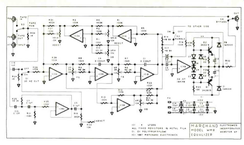
Fig. 5--Schematic diagram of the Bassis; one channel shown.
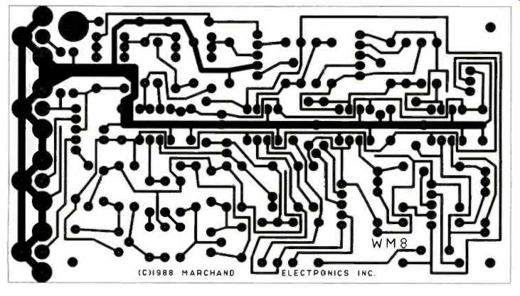
Fig. 6--Circuit-board foil pattern, actual size.
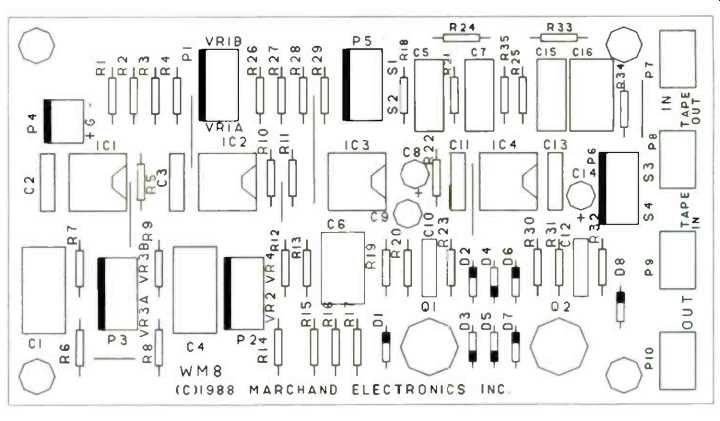
Fig. 7--Parts placement for circuit board.
==========
P.C. BOARD PARTS LIST
Resistors
All are 1%, metal-film types; one required per channel
R1, R2, R5, R11, R12, R13, R19, R22, R28, R29, and R35-100 kilohms
R3 and R27-133 kilohms
R4 and R26-402 kilohms
R6, R9, and R25-40.2 kilohms
R7 and R8-137 kilohms
R10-33.2 kilohms
R14 and R17-49.9 kilohms
R15-52.3 kilohms
R16-162 kilohms
R18-392 kilohms
R20 and R31-22.1 ohms
R21-158 kilohms
R23 and R30-10 kilohms
R24 and R34-1 megohm
R32 and R33-10 ohms
Jumpers: Seven required per channel
Potentiometers
All are 10-kilohm, linear types; one required per channel VR1 and VR3-Dual VR2 and VR4-Single Capacitors
One required per channel C1 and C4--0.039 µF, 2%, polypropylene C2, C3, C10, C11, C12, and C13--0.1 µF, ceramic C5, C7, and C15--0.1 µF, polyester film C6 and C16--1.0 µF, stacked film C8 and C14-10 µF, 50 V, aluminum C9-10 µF, 25 V, aluminum, nonpolarized
Diodes
One required per channel
D1 and D8--1N4004
D2 through D7--1N4148
Transistors
One required per channel
Q1--2N2905
Q2--2N2219
Integrated Circuits
One required per channel IC1 through IC4--LF353N
Miscellaneous
Quantities listed are per channel
Eight-Pin IC Sockets--Four required
Three-Pin Molex Connectors-One male required, one female required
Five-Pin Molex Connectors--Five male required, five female required
Molex Terminal Pins--30 required
TO-5 Heat-Sinks--Two required
Phono Jacks-Four p.c.-board types required
22 AWG Stranded Hookup Wire--80 inches each required in brown, red, orange, yellow, and green
Heat-Shrink Tubing
POWER SUPPLY PARTS LIST
2 1-kilohm, 1/4-watt resistors
2 10-µF, 25-V capacitors
2 1,000-µF, 35-V capacitors
6 1N4004 diodes
2 LEDs
1 7815, +15 V regulator
1 7915,-15 V regulator
1 117/36-V, center-tapped, 0.35-ampere transformer
1 A.c. line cord
==========
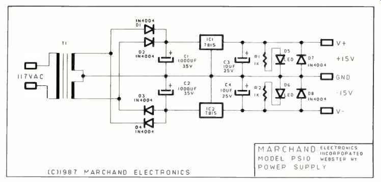
Fig. 8--Schematic of suggested power supply.
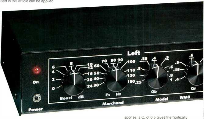
Potentiometers VR2 and VR3 are used to match the Bassis to the characteristics of the speaker. Potentiometer VR2 (the "Qs" control on the front panel) matches the speaker's damping, for speakers having Qs of 0.4 to 1.6. Dual potentiometer VR3 (the "Fs" control) adjusts the frequency matching the speaker's corner frequency over the range from 30 to 130 Hz.
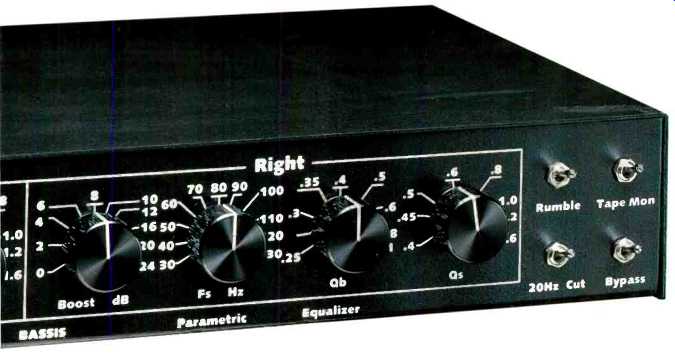
Potentiometers VR1 and VR4 are then used to set the characteristics of the desired new bass response. The new corner frequency is set by VR1 for values of fb from fs to one-fourth of fs; however, this control is labeled "Boost," and calibrated from 0 to 24 dB, because each octave of bass extension requires a 12-dB boost at low frequencies. The damping of the new bass response is set by VR4 ("Qb") for values of Qb from 0.25 to 1. Switch S1 ("20 Hz Cut") activates a high-pass infrasonic (or "subsonic") filter having a slope of 18 dB per octave below 20 Hz. This ensures that even with "Boost" set at maximum, there will be little or no boost of record warps, whose signals are below the audible range in the vicinity of 6 to 10 Hz.
Switch S2 ("Rumble") combines the left and right channels at frequencies below the speaker's original corner frequency. Since the bass information on records is frequently summed to mono, S2 cancels the out-of-phase rumble components, which would otherwise be accentuated by the ¡equalizer's boost, without cancelling the bass content of the music. Of course, it should not be necessary to use either switch when playing CDs.
Switch S4 ("Bypass") removes the equalizer. from the signal path, and switch S3 ("Tape Mon") allows you to regain tape monitoring capability, in the event that the Bassis is used in the sole tape loop of a receiver or preamplifier.
If you are designing your own speaker system and enclosure, or know the values of your particular speaker's fs and Qs, you may choose to eliminate pots VR1, VR2, and VR3 by substituting fixed resistors which reflect your speaker's parameters and provide a fixed degree of boost. This allows one dual pot (VR4) to control the damping of both channels. Since the setting of Qb influences the level of bass near the new cutoff frequency (compare Figs. 3 and 4), you retain control of the effective bass extension. (The formulas for calculating appropriate resistor values are given in the next section.)
ASSEMBLY
Figure 6 shows the p.c. board pattern for those who wish to build the circuit from scratch. Various kit versions, including drilled and etched boards and detailed instructions, are available, as is a fully assembled unit (see "Source"). Assembling the p.c. board is reasonably straightforward, requiring only a little prior experience with a soldering iron. Other useful tools include a wire cutter and stripper, needle-nose pliers, a desoldering bulb or solder wick, and a project holder such as Radio Shack's Helping Hands (#64-2093). A clean, well-lit working area will help minimize frustrations. Allow about two hours for each board (unless you are experienced) plus a few hours to wire the potentiometers and switches and to assemble the enclosure.
Mount the jumpers, resistors, IC sockets, diodes, capacitors, transistors, phono sockets, and male Molex connectors on each p.c. board according to the layout diagram in Fig. 7 and the Parts List. Be sure lo observe the polarity and orientation of the electrolytic capacitors, diodes, transistors, IC sockets, and connectors. Try to solder the transistors quickly to avoid damage. Don't forget to mount the TO 5 heat-sinks on the transistors and to orient the op-amps properly in their sockets.
The potentiometers and switches are connected by multi-colored wires to female Molex connectors; complete wiring instructions are given in the manual which accompanies each Bas sis kit or board. If you are building the unit from scratch, follow the schematic (Fig. 5). A ± 15 V power supply, such as the one whose circuitry is shown in Fig. 8, is also connected to the p.c. board via Molex connectors.
As mentioned earlier, if you're building your own speaker system, you can also build a custom version of the Bas sis, eliminating seven of the eight rotary controls. Leave out the Molex connectors which attach VR1 and VR3 to the p.c. board. Using Figs. 5, 6, and 7 for guidance, wire only that part of Molex connector P2 which attaches VR4 to the p.c. board. Now recalculate the values of resistors R7, R8, R16, R4, and R26 according to your particular speakers and the amount of boost desired, using the following formulas:
R7 or R8 = 2x7rxfsxC1 1 R16 = R19xQs b R4 or R26 = R28 x 1040
where b is boost, in dB. Now you can use a dual, 10-kilohm linear pot to adjust the damping (Qb) of the left and right channels simultaneously. Or, if you also want to eliminate the remaining rotary control, remove VR4 and recalculate R11 for the desired (fixed) value of Qb:
R11 = R2 x Qb
Mount the p.c. boards on standoffs in the Bassis cabinet; next, mount the pots and switches. Double-check all the wiring and the orientation of the components. Make sure you've mounted all the jumpers onto the p.c. boards.
ADJUSTMENT AND USE
The Bassis may be inserted into a tape loop just like a cassette deck (make sure to press your system's tape monitor button to hear the effect) or between preamp and power amps if you own separates. If bi-amplification is desired, the Bassis may be used in conjunction with an active crossover, and may thus appear only in the signal path of the low-frequency drivers.
Upon turn-on, slowly advance your system's volume control (or your power amp's gain control) to make sure the unit is operating properly. If the power light of the Bassis fails to come on, if silence or distorted sound is produced, or if your woofer cones show visible displacement (which indicates a d.c. offset), unplug the Bassis and recheck its power supply and all of the wiring.
==========
SOURCE
The following components are available from Marchand Electronics (1334 Robin Hood La., Webster, N.Y. 14580) and come with a detailed assembly manual: WM8-AA Fully assembled and tested Bassis equalizer, $345 WM8-KK All parts for stereo Bassis equalizer (two boards, plus parts, power supply,. cabinet, and hardware), $225 WM8-A Fully assembled and tested WM8 single-channel p.c. board, $84.95 WM8-K WM8 single-channel p.c. board and parts, $59.95 WM8-B Drilled, etched, and silkscreened WM8 single-channel p.c. board, $14.95 PS10-A Fully assembled and tested power supply, $44.95 PS10-K Kit for power supply, $39.95 PS10-B Bare board for power supply, $12.95 WM8-C Cabinet, $59.95
Add $2.50 per order for shipping and handling; New York State residents, add 7% sales tax. Write to Marchand Electronics for more detailed pricing and a catalog of audio kits.
==========
Four knobs per channel control the unit's operation: "Boost," "Fs" (speaker resonance), "Qb" (damping), and "Qs" (speaker damping). Before using the Bassis, you must set these controls for proper correction of your loudspeakers' response. Usually, you will set the controls for the left and right channels identically. If you own vented (bass reflex) speakers, you must either leave the "Boost" control at zero or plug the vent to obtain acoustic-suspension operation. (Again, plugging the vent and applying equalization may give you more accurate and extended bass at the expense of efficiency and power handling. If you plug the vent, your speaker will probably have a relatively low, overdamped cutoff; e.g., an fs of 50 Hz and a Qs of 0.5.) Referring to Fig. 1, you must estimate your speakers' corner frequency and damping. Most good acoustic suspension speakers will have Qs between 0.6 and 1.0. The more tight sounding British speakers will be closer to 0.6, while heavy- or loose-sounding speakers will fall closer to 1.0. The setting of Qs is not terribly crucial and, in any event, may be adjusted by ear to account for your tastes and the effects of your listening room. If in doubt, start with a setting of 0.7. Note that a Qs setting which is too high will reduce the net bass response.
You can estimate fs from the specs for your speakers' frequency response. These specs are usually of the form: "50 Hz to 20 kHz, ±3 dB." This means the bass response may be reduced by anywhere from 3 to 6 dB at the lower stated frequency (depending on how conservative the specifications are). Suppose your speakers' -6 dB point is at 50 Hz. Look at the curve in Fig. 1 which corresponds to your estimate for Qs. Suppose the -6 dB point on this curve is at 0.7 multiplied by (f divided by fs). Then an estimate for fs would be 50 Hz divided by 0.7, or about 71 Hz.
If you don't have specs for your speakers, note that small speakers with poor damping (Qs greater than 1) can often sound like they have more bass extension than they really do. Unless you are confident of your ability to distinguish lower bass from mid-bass, you may wish to use the following estimate for fs: Most medium-size bookshelf speakers have fs around 65 Hz; compact speakers (enclosures less than 14 inches high) usually fall closer to 80 Hz; large speakers may have fs around 40 to 50 Hz. For those tiny diecast speakers, such as Radio Shack's ubiquitous Minimus 7, try a value of 100 Hz or higher for fs and around 0.8 or 0.9 for Qs. Again, this latter setting is not crucial and can be readjusted later, if necessary.
The fs and Qs settings may never need readjustment. However, you can vary the boost and Ob settings for your particular listening preferences. As mentioned previously, the "Boost" control determines the total amount of boost applied at frequencies below your speakers' natural corner frequency. Every 12 dB of boost extends the response one octave lower. For example, a setting of 24 dB will extend response from 60 Hz down to 15 Hz-if your amp and speakers can handle it. The " Ob" control allows you to set the damping of the new response. Low settings, as seen in Figs. 1 and 2, give a falling response with no ringing.
When listening at high levels, it may be wise to reduce the amount of boost and/or to reduce the Ob setting.
The Bassis must be used with care to avoid damage to your speakers. If you are using a phono source, set your system's volume control to your usual listening level, remove the grilles from
your speakers, and observe the woofers while playing the silent lead-in groove of a record. If you see a significant pumping action with "Boost" set at 24 dB, you may have to engage the "20 Hz Cut" switch. This filter attenuates frequencies below 20 Hz, where bass boost can emphasize signals generated by record warps. On some occasions, you may also choose to engage the "Rumble" switch to reduce the audibility of turntable rumble and to further reduce the effects of record warps. It is unwise (and unnecessary) to engage your system's loudness button or to turn up its bass control while using the Bassis.
Note that it is possible to introduce a peak in the midbass by setting Qs too low for your speaker or by setting fs too high. Although this may add an agreeable weight to some recordings, please be aware that there is likely to be much more energy present in music in this range than in the very low bass.
Hence such an incorrect adjustment may cause greater stress to your amplifier and speakers than is caused by the sort of low bass boost for which the Bassis is intended.
When used properly, the Bassis can transform your speakers into truly wide-band transducers having ideal transient response, and it can help you match your speakers to the acoustics of your listening room. Further, the Bassis doesn't take up so much as 1 cubic foot of that room.
---------------
Also see: AUDIO Etc. (Apr. 1990)
= = = =