(Continued from MARCH 1973)
By Martin Clifford
The Phono Cartridge
The stylus fits into the cartridge, which, in turn, is mounted in a shell at the tip of the tonearm. As the stylus tracks in the rotating grooves, it is deflected laterally and vertically; depending on the modulations inscribed in the groove walls. In theory this sounds easy enough, but if the stylus is to track well, it must follow the complicated meanderings of the groove instantly and it must do so without bottoming (that is, without hitting the bottom of the grooves), without losing contact with the walls, yet not pressing unduly hard against them, and without jumping out of the grooves. Further, its contact or pressure must be the same against both walls--inner and outer--despite the fact that the very motion of the stylus makes such an equilibrium very difficult. To be able to do all this, the mass of the stylus and moving parts must be kept as little as possible, since the greater the moving mass, the greater its inertia-that is, the greater its resistance to quick changes in motion. And so the conditions for good tracking are quite difficult. But these aren't the only requirements. There must be a sufficient downward force, known as tracking force, on the stylus, to keep it in the grooves. Too much will cause stylus and records to wear out more quickly than necessary.
The stylus assembly must have freedom of movement--technically called trackability of compliance. The greater the compliance, the smaller the tracking force required. And since the stylus is going to wiggle around thousands of times a second as the record rotates beneath it, it becomes obvious that with high compliance we are permitting the stylus to do its job, to follow even the most delicate tracings in the groove walls.
In spec sheets you may find compliance listed for both dynamic and static conditions. Compliance is specified in terms of centimeters per dyne, usually written as cm/dyne. The cm figure means the amount of deflection, in centimeters, that a force of 1 dyne upon the stylus will produce. The larger the figure the better. It also depends on the tracking force and should be at least 8 X 10 cm/dyne. 8 X 10^-6 is just a scientific and easier way of writing 0.00008, and so a stylus with such a compliance will move 0.00008 centimeter when a force of 1 dyne is applied. The dyne is a unit of force, just as an inch is a unit of linear measurement, or an ounce is a unit of weight.
A quality cartridge would have a compliance of 15 or 20 X 10^-6 cm/dyne or possibly more, while the cheapies go down to around 3 to 5 X 10^-6 cm/dyne.
Dynamic compliance is usually measured at some spot frequency, possibly at 100 Hz.
Tonearm
No cartridge is an island unto itself, for it must form an integral part of the tonearm on which it is mounted. A cartridge can only deliver its full performance if it is joined with a tonearm of equally high quality. The tonearm's main function is to hold the cartridge in its path while it travels across the record, and to apply the necessary tracking force while compensating for other, unwanted forces. Neither the stylus, the cartridge or tonearm must acquire delusions of grandeur, but since they are working under conditions in which vibration is the order of the day, it isn't too surprising to find that these elements would like to resonate. And they do and when they do they form sound sources of their own, contributing their mite to the overall sound. An unwanted mite for they form no part of the original sound source inscribed on the walls of the disc. The best thing to do with unwanted resonances is to kill them. If that isn't possible, attenuate them. And if that isn't possible, to try to make the resonant frequencies move down into a sub-audible frequency.
Most high-quality tonearms are made of some lightweight metal alloy, supplying maximum structural strength with a minimum of weight and ease of machining. Tonearms in the past have taken on some fancy configurations, but most can be grouped into three types: the straight or I-shaped, J-shaped and S-shaped (Fig. 6). In each instance, though, the shell-cartridge assembly forms an angle with the tonearm axis.
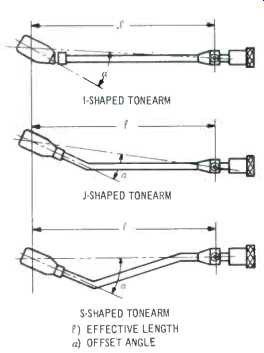
Fig. 6. I-, J-, and S-shaped tonearms.
The arm axis is an imaginary line drawn between the tip of the stylus and the tonearm pivot. This angle is known as the offset angle and its purpose is to minimize the tonearm's tracking error.
Tracking angle is the angle that the cartridge axis deviates from the record tangential at any given point on the record. The smaller the tracking error, the better. It should not exceed 2° to 3°.
Integrated Arms
On some economy type equipment the shell cannot be removed from the tonearm and so such units are known as integrated arms. Most modern tonearms, however, have standardized plug-in connections for the cartridge-shell assembly, so that all cartridges following these standards can be interchanged.
Problems of the Offset Angle
While the tonearm's correct offset angle helps minimize tracking error, it introduces a problem of its own. It results in what is known as 'skating force' a force which pushes the pickup toward the center of the record. Thus, instead of tracking both groove walls with equal force, it is much greater on the inner groove wall than the outer.
This can produce two effects, both undesirable. One of these is uneven wear, with the possibility of decreased record life. The other is distortion due to insufficient tracking force on the outer wall.
To place all the blame for skating force on offset angle is a simplification, for a tricky combination of forces act on the stylus and tonearm as they track the record. In extreme cases, the effect is to cause the stylus to jump out of the groove. To assure perfect tracking of both groove walls-that is, both stereo channels-some compensating force is used. In one method a little weight affixed to a string applies a corresponding counterforce on the tonearm.
Another technique is the magnetic type anti-skating device which employs the repulsion power of magnetism. As the skating force varies with stylus tracking force, the anti-skating device should be readjusted each time the tracking force is changed.
Cartridge Types
There are various systems for converting the vibrations of the stylus into an equivalent electrical signal. Ceramic cartridges (Fig. 7) take advantage of the fact that certain crystalline materials develop a voltage when they are subjected to stress, such as a twisting action.
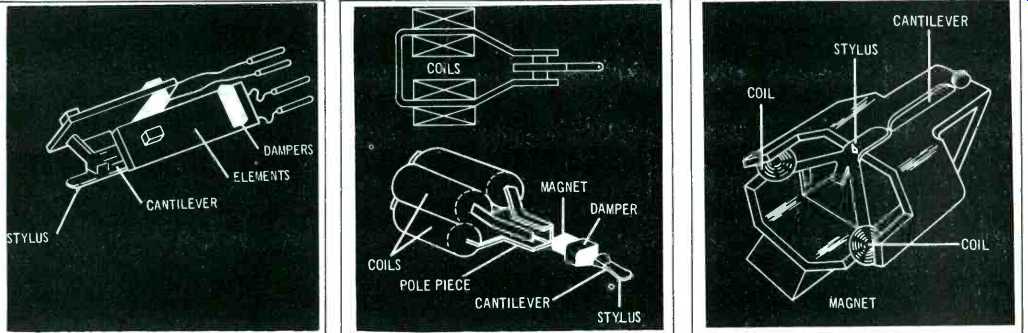
Fig. 7. View of a ceramic cartridge. Fig. 8. The moving magnet (MM) cartridge.
Fig. 9. The moving coil (MC) cartridge.
Movements of the cantilever (which is affixed to the stylus) apply varying forces, twists and pressures, on a special crystallic material which generates an electrical voltage in accordance with the stylus movement. The rigid armatures required to exert this twisting force naturally increase the moving mass, and the ceramic elements are sometimes affected by heat and moisture. Ceramic cartridges are more commonly used in low-priced record players.
Various types of magnetic cartridges are available. The moving magnet (MM) cartridges (Fig. 8) have a tiny permanent magnet attached to the cantilever which moves freely between an assembly of coils, inducing a voltage in these coils. Moving magnet cartridges have the benefits of a small moving mass and high efficiency--that is, relatively high output voltage.
The reverse principle is applied in moving coil (MC) cartridges (Fig. 9). Here the magnet is fixed, and the coils--one for each channel--move in the magnetic field, receiving an induced voltage in the process. The moving mass of moving coil cartridges is even smaller than that of the moving magnet type, but they have quite a small output voltage. Both types, moving magnet and moving coil cartridges, do supply good frequency response and stereo channel separation.
Still another magnetic cartridge is the induced magnet (IM) with fixed magnet and coil assemblies (Fig. 10). Two tiny iron plates move in the magnetic field, causing variations in the magnetic flux. Because of the changes in magnetic flux lines, a voltage can be induced in the coil assembly.
The output voltage of the cartridge is usually measured at a specific frequency, such as 1,000 Hz and at a certain stylus-to-groove velocity. The voltage output will depend on the kind of cartridge used, but should always be greater than the sensitivity (expressed in millivolts) of the amplifier's phono input.
The frequency response of the cartridge represents the entire range of audio the cartridge will deliver. A wide range is desirable, with no peaks or dips within the range. A quality cartridge should extend from 20 Hz to 16 kHz, ±3 dB, or better.
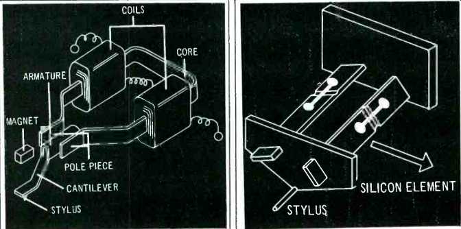
Fig. 10. The induced magnet(IM) cartridge. Fig. 11. The semiconductor cartridge.
While magnetic cartridges are the generally accepted types, others have been proposed. Thus, there are two not being widely used, although they hold excellent promise. One is the semiconductor (Fig. 11) cartridge in which mechanical forces created by stylus vibration change the electrical resistance of a silicon semiconductor in correspondence to stylus vibration. Another is the photoelectric in which light from a tiny bulb in the cartridge falls on a phototransistor which converts it into an electric voltage.
Impedance
In its broadest sense, impedance means opposition to the flow of an electric current. Low impedance and high impedance do not imply quality, for the words low and high have no relationship to value in this sense.
Impedance is like friction. On an icy road you want lots of it between your tires and the surface, while some of it is necessary at all times. Impedance is one of the descriptive factors of electronic components. A speaker has impedance. A tuner or receiver has several: one at the input, the other at the output.
As a rule, when individual components are connected, it is desirable to match impedances-the output impedance of one component should match the input impedance of the component to which it is connected. This rule should be prefaced by 'generally' since, as in the case of many rules, there are desirable exceptions.
In the case of cartridges, load impedance is the input impedance of the amplifier. The amplifier is the load, or the device to which the tonearm will deliver its electrical signal. For MM and IM pickups, the standard impedance is about 47,000 ohms to 50,000 ohms, with the ohm being used as the basic unit of impedance. Most amplifier phono inputs are designed for this. MC cartridges have low impedances: 2 to 10 ohms, and so the amplifier to which this cartridge will be connected must have special MC phono inputs. Otherwise, a step-up transformer or booster amplifier will be required between the MC cartridge and its following amplifier.
Automation
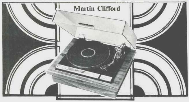
Convenience is the keynote in the modern record player and automatic record changer. One step in the direction of automation is the 'auto return' tone arm in which the arm is raised and lowered by a button type oil elevation device. At the end of the record, it lifts off and returns to its rest position automatically. The logical extension of this is the fully automatic turntable (Fig. 12). A single function controls the entire operation. In position start, the tone arm moves over the initial record grooves, the platter begins to revolve, the tonearm floats down, the record is played, and at the end of the play the tonearm lifts off and returns to its rest position. There are usually two other controls: a speed selector and a record size selector which adjusts the tone arm drop point for various record diameters.
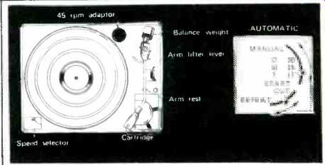
Fig. 12. Turntable with automatic features.
A record player is a sound source, just as a tuner, or cassette deck, or microphone, are regarded as sound sources. The sole function of the record player is to extract the information modulated into the walls of the record grooves and to deliver that information in the form of an electrical signal to a pre-amp. It is hi fi only to the extent to which it does this. If the record player, in part or in toto, behaves like a signal source in any way, then to that extent it is not high fidelity.
Audio For Beginners
Radio waves are far from genteel, for they cannot be so and survive. But the strongest signal isn't always the most preferable, and so we now have tuners capable of reaching out and succoring those emaciated signals that, a technical decade ago, would have perished. That ability of a tuner to respond to the weakened remnant of a signal is called sensitivity, a good word, a pleasant word, but a most unfortunate one since it implies a certain sensibility and kindness on our part. Nothing of the sort, of course.
We want tuners having high sensitivities to be able to pick up weak signals for the sole practical reason that those signals may be the ones we want. The desideratum of a signal isn't its strength or ability to survive, but simply a relationship to our own personal wants.
The FM band covers a range of 88 107.9 megahertz, a total of almost 20 megahertz. You can realize how wide this band is by comparing it to the AM broadcast band which extends from 535 to 1635 kilohertz, a total of 1100 kilohertz or 1.1 megahertz. And so the FM band is approximately 20 times as wide as the AM band. Into this FM band playroom are crammed all the broadcast FM stations with each occupying individually much more band space than comparable AM stations.
AM vs FM
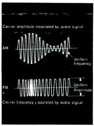
Fig.13--In AM, the carrier strength or amplitude changes during modulation.
With FM, the carrier strength remains unchanged.
Per se, audio waves have a very short travel span. If you want to know how far audio waves can travel unassisted, and are willing to experiment in the name of science, try shouting out of your bedroom window in the quiet early morning hours. If you can avoid capture and confinement, you will have learned that the distance covered by your voice is a few hundred yards, if that. To overcome this limitation, at the broadcast station the audio signal is electronically loaded on another, much higher frequency wave, called a carrier for very obvious reasons. (The carrier is the assigned frequency in the FM band). The loading process is called modulation, whether for AM or FM (Fig.13). The reverse process in the tuner, that of discarding the carrier and recovering the original audio signal, is demodulation. Amplitude modulation, or AM, changes the strength or amplitude of the carrier wave; frequency modulation changes its frequency.
(to be continued)
(Audio magazine, May 1973)
Also see:
The Language of High Fidelity--Part IX: Record Players (part a) (Mar. 1973)
The Language of High Fidelity--Part VIII (Feb. 1973)
The Language of High Fidelity--Part VII: The Basic High-Fidelity System (Dec. 1972)
Language of High Fidelity--Part XI (May 1974)
= = = =